Socrates Pantelides, for their comments and encouragement, but also for the difficult question that prompted me to expand my research from different perspectives. Last but not least, I want to thank my parents, Shengguo Liao and Bo Jiang, for giving birth to me and supporting me throughout my life.
INTRODUCTION
O VERVIEW
O BJECTIVES AND A PPROACH
S TRUCTURE OF THE DISSERTATION
BACKGROUND
R ADIATION E NVIRONMENT
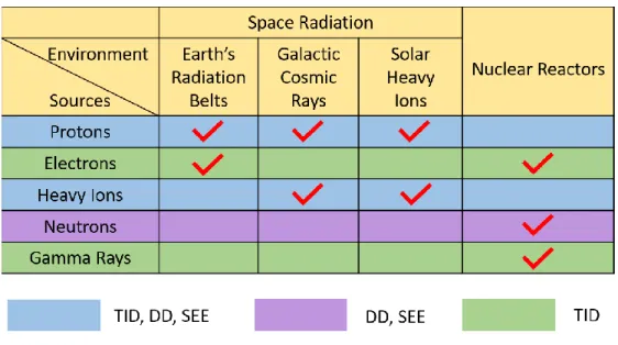
- Space Radiation
- Nuclear Reactors
Although there is no specific division, the outer extent of the inner belt is usually taken to be 10,000 km. A nuclear reactor's control building houses most of the equipment that must be radiation-hardened.
M ICROELECTROMECHANICAL S YSTEMS
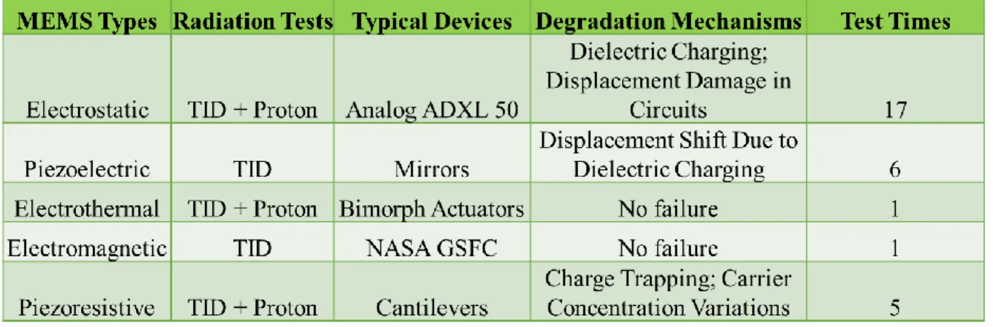
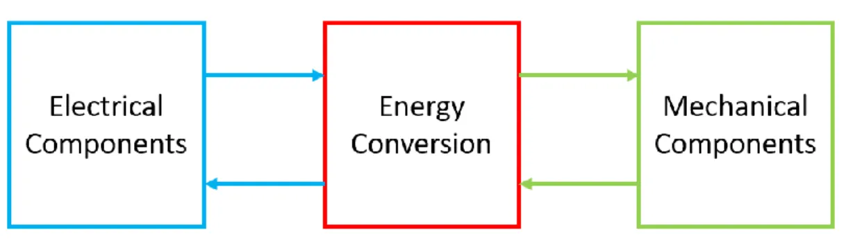
The changes of electrical properties can lead to changes in mechanical components through energy conversion mechanisms. The study of radiation effects on electronic components has a decades-long history, while the study of radiation effects in mechanical parts is more limited.
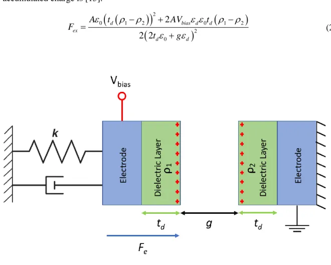
R ADIATION E FFECTS ON E LECTROSTATIC MEMS
Fex is inversely proportional to the distance g between MEMS and the equivalent dielectric layer and is a function of dm. The MEMS resonance frequency tuned by the electric field in Figure 2.4 can be expressed as:
R ADIATION E FFECTS ON P IEZOELECTRIC MEMS
- Piezoelectric Effects and Piezoelectric Micromachined Acoustic Sensor
- Previous Investigation of Radiation Effects on Piezoelectric MEMS
The compliance, mass and damping of the piezoelectric diaphragm are normally represented in the mechanical domain. More recently, researchers have begun to investigate the piezoelectric properties of thin films of the material.
R ADIATION E FFECTS ON E LECTROTHERMAL MEMS
- Stress, Strain and Electrothermal Bimorph Actuator
- Previous Investigation of Radiation Effects on Electrothermal MEMS
The electrothermal actuator is generally characterized by the relationship between the amount of tip deflection and the applied voltage. The graphs in Figure 2.9 represent the average measured tip deflection plus and minus the standard error in the measurements.
![Figure 2.8 Isometric drawing of horizontally deflection electrothermal actuator. (Caffey [37]) Figure 2.8 is an illustration of a horizontally-deflecting electrothermal actuator used for radiation tests by Jared R](https://thumb-ap.123doks.com/thumbv2/123dok/10732680.0/28.918.130.783.611.855/isometric-horizontally-deflection-electrothermal-illustration-horizontally-deflecting-electrothermal.webp)
R ADIATION E FFECTS ON 2D MEMS
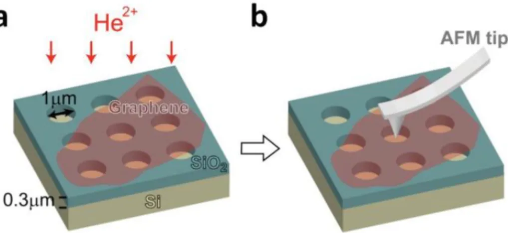
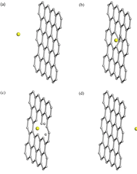
In Figure 4.9(a), the simulated surface charge density in the SiO2 layer overlying the cantilever beam is chosen at the high end of the range of expected radiation-induced positive charge densities, 1×10¹²/cm2, for purposes of illustration. This means that the incident ion 'passes' through the graphene layer without changing direction, while the struck carbon atom continues to move in the graphene plane. Liao et al., “The study of radiation effects in emerging micro- and nano-electromechanical systems (M and NEMs),” Semiconductor Science and Technology, vol.
McDonald et al., "Radiation Effects in MEMS Accelerators," IEEE Transactions on Nuclear Science, vol. McLean et al., “Effect of ionizing radiation on PZT sol-gel ferroelectric capacitors,” IEEE Transactions on Nuclear Science, vol. Ko et al., “Effects of proton irradiation on electrothermal micro-actuators,” Canadian Journal of Electrical and Computer Engineering, vol.
Zhan et al., “The effect of layer number and substrate on the stability of graphene under MeV proton beam irradiation,” Carbon, vol.
C ONCLUSIONS AND L ITERATURE G APS
RADIATION EFFECTS ON PIEZOELECTRIC MEMS
- O VERVIEW AND O BJECTIVES
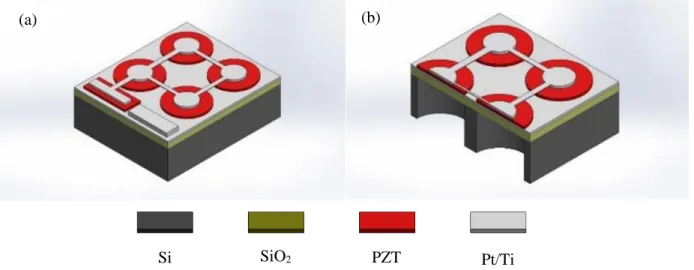
- D EVICE S TRUCTURE AND S AMPLE P REPARATION
- P IEZOELECTRIC MEMS L UMPED M ODEL
- X R AY I RRADIATION E XPERIMENTS
- E XPERIMENTAL R ESULTS AND D ISCUSSION
- C ONCLUSIONS
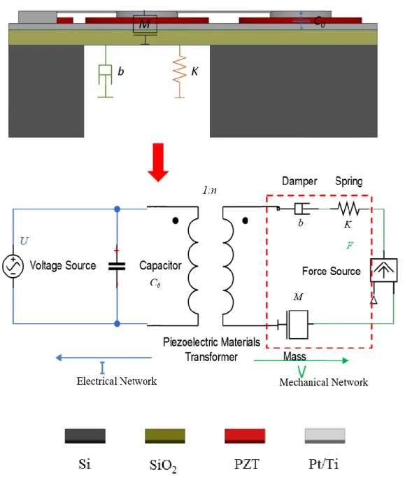
These trapped charges change the strain and voltage in the PZT membrane due to the reverse piezoelectric effect and therefore shift the resonant frequency. Finally, we note that the resonant frequency variation of a piezoelectric resonator is. proportional to the vertical electric field, and can be expressed as [53]:. This shows that changes in resonance frequency are linear with changes in radiation-induced charge density.
8 are consistent with the X-ray results, confirming the strong effect of radiation-induced charge on the resonant frequency and quality factor. The resulting close match between the COMSOL simulations and the 0 V bias test results is shown in Figure 3.10, confirming the strong effect of the accumulated charge on the resonant frequency. In this chapter, the pMUT resonance frequency and quality factor response to 10 keV X-ray irradiation are investigated.
The mechanical resonance frequency and quality factor of pMUTs are derived from equivalent LRC circuits.
RADIATION EFFECTS ON ELETROTHERMAL MEMS
- O VERVIEW AND O BJECTIVES
- D EVICE S TRUCTURE AND S AMPLES P REPARING
- B IAS S TRESS AND X RAY I RRADIATION
- X R AY AND B IAS T EST R ESULTS
- O XYGEN I ON I RRADIATION E XPERIMENTS
- D ISCUSSION
- Scanner Plate Charging
- Bimorph Cantilever Charging
- C ONCLUSIONS
Then the image was refocused, and the z-position reading of the scanner plate was recorded. The image was refocused at each voltage and the corresponding z-position reading of the scanner plate was recorded. The displacement of the plane of the scanner plate at each test voltage is derived from the z-position curve.
Consequently, radiation-induced charges cause long-term changes in the equilibrium position and resistance of the microscanner. In this regard, Figure 4.8 shows the results of SRIM simulations [71] of ionizing energy loss in one of the bimorph cantilever structures. In addition to scanner plate loading, bimorphic cantilever structures (Figure 4.1) almost certainly contribute to radiation-induced changes in resistance and z-position of the microscanner.
The resulting electrostatic forces lead to changes in resistance, position and orientation of the microscanner.

MONTE CARLO SIMULATION OF RADIATION EFFECTS ON GRAPHENE
O VERVIEW AND O BJECTIVES
SRIM, a Monte Carlo computer code to calculate how a moving ion transfers its energy to target atoms in bulk materials, may not be directly applicable to two-dimensional (2D) systems; the sample is treated as an amorphous matrix with a homogeneous mass density in SRIM while clear accounting for the atomic structure is very important in evaluating the effects of radiation on graphene. In this chapter, the objectives include: (1) Investigation of ion bombardment on graphene, (2) Programming of the new Monte Carlo method. 3) Monte Carlo calculation for multilayer graphene and other 2D materials.
D IFFERENT T YPES OF D EFECTS IN G RAPHENE
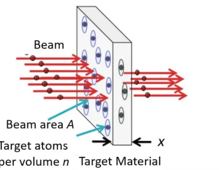
B INARY C OLLISION M ODEL
The BCA is a high-energy approach, especially suitable when high-energy encounters dominate the phenomena under investigation. At low energies, where recoil trajectories are less easily represented in terms of discrete collisions, the BCA becomes less useful. On the other hand, relativistic effects must be taken into account at ultrahigh energies.
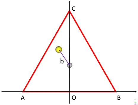
In general, the BCA approximation should be appropriate for ion energies in the range of. The impact parameter b shown in the figure is defined as the perpendicular distance between a projectile and the center of a potential field created by a carbon atom that the projectile approaches. The collision of an electron or ion with a carbon nucleus can be treated using a simple Coulomb potential, since the screening effect of the surrounding electrons can be neglected [94].
The minimum energy transferred to the atom required to produce a vacancy-interstitial (Frenkel) pair that does not recombine spontaneously is called the displacement energy Ed.

A TOMIC S TRUCTURE AND I MPACT P ARAMETER
As Figure 5.5 shows, the target carbon nucleus is located at the center of the equilateral triangle with coordinates (0, L/2). The horizontal coordinate of the incident ion is a random variable uniformly distributed among the points. A point and B. The vertical coordinate of the incident ion is also a uniformly distributed random variable, and its uniformly distributed range can be derived from its corresponding horizontal coordinate.
Normally, the incident ions come from a particle accelerator and the kinetic energy E follows a normal distribution. Then, using formula (5-1) to (5-3), the scattering angle θ of the projectile, the scattering angle ϕ of the carbon atom and the kinetic energy E1 of the carbon atom after the collision are calculated. Finally, the post-collision motions of the carbon atoms are analyzed based on the statistical results of the Monte Carlo simulation.
A complete execution of the proposed Monte Carlo simulation (written with MATLAB code; see Appendix) on Intel i5-4670 and Windows 10 Pro takes less than 1 min.
S MALL A NGLE S CATTERING AND IN P LANE C ASCADE C OLLISION
The energy-depleted target carbon atom continues to move in the plane of graphene and causes cascading collisions with other carbon atoms in the graphene sheet, as shown in Figure 5.7(c). Defects in the graphene sheet arise from primary ion collisions and subsequent carbon atom cascade collisions in the plane of the graphene. Cascade collision in the plane of graphene still dominates the post-collision motion of carbon atoms.
The defects in the graphene sheet can be calculated by adding the Frenkel pairs generated in the primary ion collision and monitoring the cascade collisions of the carbon atom in the graphene plane. Because the number of cascade collisions that occur before the knocked-out carbon atoms leave the graphene plane is unknown, the generation of defects in the collision process is difficult to evaluate. But the proposed Monte Carlo approach can be used to estimate the upper and lower bounds of the defect numbers in the graphene.
First, assume that there are no cascading collisions of carbon atoms in the plane of graphene.
S IMULATION R ESULTS OF C I ONS WITH D IFFERENT E NERGY
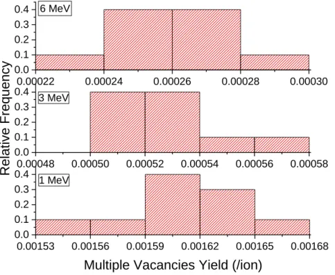
Since the number of sputtered ions from the SiO2 surface is 0 (calculated by SRIM), the substrate should have little effect on defect generation in the graphene. The defect yield, single vacancy yield and multiple vacancy yield are inversely proportional to the incident ion energy. As the incident energy E increases, b1 and b2 decrease and the area outside the green ring increases.
The production of defects in graphene under ion irradiation with different incident energies has been simulated by the analytical potential molecular dynamics [97]. The reported defect yield, single vacancy yield, and double vacancy yield decrease as the incident energy increases within the high energy range, which shows good agreement with our analysis results. From formulas (5-5) and (5-6), the yield on defects, the yield on a single vacancy, and the yield on multiple vacancies should increase with increasing atomic number.
For each incident energy we perform ten Monte Carlo simulations and the results are shown in Table 5.1 and Figure 5.12.
C OMPARISON WITH E XPERIMENTAL I RRADIATION R ESULTS
This is because we assume that all the scattered target carbon atoms collide with other carbon atoms in the graphene plane. A small percentage of carbon atoms with a larger scattering angle leave the graphene plane after several collisions. The proposed Monte Carlo simulation can simulate this random process and provide a satisfactory approximation of the experimental results in a short time.
In the Monte Carlo simulations, each ion is calculated assuming no damage in the graphene. For example, when the void density in graphene increases, the average distance between two carbon atoms in the graphene increases. This means that the probability P (E1 > Ed) decreases and the defect yield is lower than what we get from the Monte Carlo simulation.
However, as the number of graphene layers increases, the scattering angle of the target carbon atom decreases and fewer cascade collisions occur in the graphene plane.
C ONCLUSIONS
It can also be used to estimate the defect yield in different layers of graphene, as most of the high incident energy ions "penetrate" through the graphene layer with little energy loss.
SUMMARY AND PERSPECTIVES FOR FUTURE WORK
S UMMARY OF M AIN R ESULTS
P ERSPECTIVES FOR F UTURE W ORK
Alles et al., “Total ionizing dose effects on piezoelectric micromachined ultrasonic transducers,” IEEE Transactions on Nuclear Science, vol. Tang et al., “Total dose effects on microelectromechanical systems (MEMS): Accelerometers,” IEEE Transactions on Nuclear Science, vol. Mihailovich et al., “Radiation effects in microelectromechanical systems (MEMS): RF relays,” IEEE Transactions on Nuclear Science, vol.
Sniegowsi et al., “Effects of Radiation on Surface Micromachining Drives and Micromotors,” IEEE Transactions on Nuclear Science, vol. Schrimpf et al., “Effects of total radiation dose on sol-gel-derived PZT thin films,” IEEE Transactions on Nuclear Science, vol. Alles et al., “Total Ionization Effects on an Al/SiO2 Bimorph Electrothermal Microscanner,” IEEE Transactions on Nuclear Science, vol.
McWhorter et al., "Physical mechanisms contributing to device rebound," IEEE Transactions on Nuclear Science, vol.
![Figure 2.1. The charged particles trapped by the Earth’s magnetosphere (adapted from [6])](https://thumb-ap.123doks.com/thumbv2/123dok/10732680.0/14.918.281.631.746.1032/figure-2-charged-particles-trapped-earth-magnetosphere-adapted.webp)
![Figure 2.10 Measured tip deflection after 34 mins 0 to 20 V voltage sweeping. (Caffey [37])](https://thumb-ap.123doks.com/thumbv2/123dok/10732680.0/31.918.252.673.110.458/figure-measured-tip-deflection-mins-voltage-sweeping-caffey.webp)