27 Figure 4.2 Computational domain of circular microchannel 28 Figure 4.3 Two-dimensional geometry of circular microchannel with. 35 Figure 4.6 Heat transfer coefficient variation for laminar flow (Re in circular microchannel for water and its nanofluid. 52 Figure 5.3 Computational domain of rectangular microchannel 53 Figure 5.4 Three-dimensional geometry of rectangular microchannel.
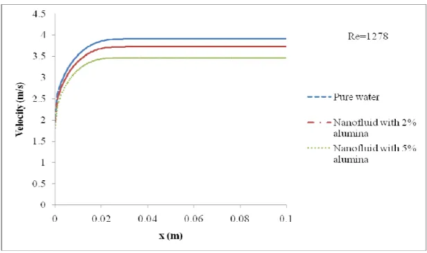
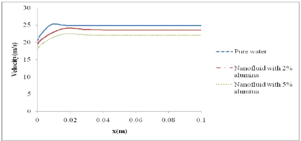
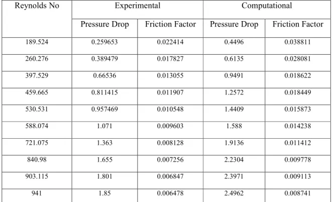
54 Figure 5.5 Velocity profile for water and its nanofluid at Re=140 56 Figure 5.6 Variation of calculated and experimental pressure drop. In microchannel heat exchangers, flow is typically laminar and heat transfer coefficients are proportional to velocity. When the temperature of the reactor must be maintained, microreactor also serves as a microchannel heat exchanger.
USE OF NANO PARTICLES 3
A microreactor is a device in which chemical reactions take place in an enclosure with typical lateral dimensions below 1.0 mm. The microreactors used in these applications are typically continuous flow reactors rather than batch reactors, with the continuous flow design providing better performance in material synthesis than is possible with batch reactors. It enables the miniaturization of the fuel processor because they minimize resistance to heat and mass transfer.
A microreactor can also be used to perform reactions on a very small scale to determine the potential for dangerous situations, such as runaway reactions or the generation of excessive heat levels.
APPLICATION OF COMPUTATIONAL FLUID DYNAMICS (CFD) 3
Numerical methods are widely used to analyze the behavior performance and also to design microchannel heat exchangers. Computational Fluid Dynamics (CFD) is a computer-based numerical tool used to study fluid flow, heat transfer behavior and also its associated phenomena such as chemical reaction. These equations are then solved using a computer program to obtain the flow variables throughout the computational domain.
Examples of CFD applications in the chemical process industry include drying, combustion, separation, heat exchange, mass transfer, pipeline flow, reaction, mixing, multiphase systems, and material processing. Validation of CFD models is often required to assess the accuracy of the computational model. Other model equations can be simulated by CFD method for micro channel design and also to do parameter sensitivity analysis.
OBJECTIVES OF THE PRESENT WORK 4
OUTLINE OF THE REPORT 5
The convective heat transfer coefficient for nanofluids was found to be greater than that of the base fluid. Numerical results for flow and heat transfer characteristics were obtained for different values. The heat transfer coefficient of nanofluids increases with the increase in volume concentration of nanofluids and Reynolds number.
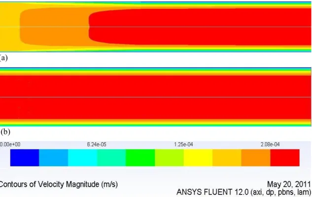
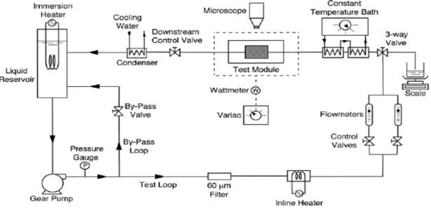
When Re decreases to 0.1 (very low value), the Pe value decreases significantly and also the residence time of the liquid in the channel increases due to decrease in the inlet velocity of the liquid. This indicates that the ciruclar mirochannel is in a fully developed flow state. The same applies to all fluid flow with water as well as its nanofluid. Experimental and numerical investigation of pressure drop and heat transfer in a single-phase microchannel heat sink.
LITERATURE REVIEW
NUMERICAL STUDY OF FLUID FLOW AND HEAT TRANSFER IN
To design an effective microchannel sink, a fundamental understanding of the heat transfer and fluid flow characteristics in the microchannel is necessary. Macroscale fluid flow and heat transfer designs and relationships were used in the early stages. The effect of suspended ultrafine metal nanoparticles on fluid flow and heat transfer processes inside the enclosure was analyzed.
It was found that an increase in the buoyancy parameter and volume fraction of nanofluids results in an increase in the average heat transfer coefficient. In the second part, recent achievements in the understanding of heat transfer in microchannels are presented. Fluid flow and heat transfer experiments were performed on a copper microchannel heat exchanger with a constant surface temperature.
NANOFLUIDS AS HEAT ENHANCER 15
It was found that the increase in experimental heat transfer coefficients is lower than the increase in effective thermal conductivity. 3.4) Where κeff is the effective conductivity (κ + κt, where κt is the turbulent thermal conductivity defined according to the used turbulence model) and Jji is the diffusion flux of type J. The first three terms on the right side of the equation represent energy transfer due to conduction, species diffusion, and viscous dissipation. Thus, the increase in heat transfer coefficient is greater in laminar flow than in turbulent flow.
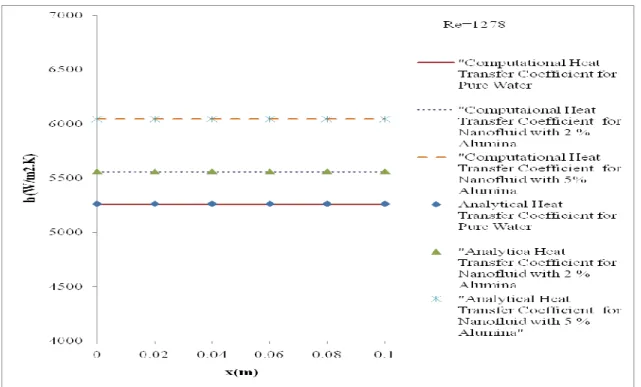
The heat transfer coefficient is constant throughout the circular micro channel due to its fully developed conditions. Variations of the bottom wall heat transfer coefficient along the microchannel at different power inputs for water and its nanofluids (1% and 2% aluminum) are shown in Fig. Numerical investigation of laminar flow and heat transfer in a radial flow cooling system using nanofluids.
COMPUTATIONAL FLUID DYNAMICS MODEL EQUATIONS
Mass Conservation Equation 20
Equation (3.1) is the general form of the mass conservation equation, and is valid for both incompressible and compressible flows. The source Sm is the mass added to the continuous phase from the dispersed second phase (eg due to evaporation of liquid droplets) and any user-defined sources.
Momentum Conservation Equation 20
3.3) Where µ is the molecular viscosity, I is the unit tensor, and the second term on the right-hand side is the volume dilation effect.
Energy equation 21
TWO PHASE MODELING EQUATIONS 22
- Volume of Fluid (VOF) Model 23
- Volume Fraction Equation 23
- Material Properties 23
- Momentum Equation 24
- Energy Equation 24
- Mixture Model 25
- Continuity Equation 25
- Volume Fraction Equation for the Secondary Phases 27
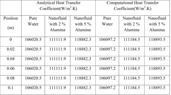
Therefore, in the present study, the analytical values of the heat transfer coefficients were calculated using Eq. The comparison shows that the CFD results can well predict the analytical heat transfer coefficient. As the concentration of nanoparticles increases, the heat transfer coefficient also increases.
The heat transfer coefficient decreases from the entrance to the exit region in a rectangular microchannel, while it is constant in a circular microchannel due to fully developed conditions. Conduction and entrance effects on laminar fluid flow and heat transfer in rectangular microchannels. Assessment of the Effectiveness of Nanofluids for Single-Phase and Two-Phase Heat Transfer in Microchannels, International Journal of Heat and Mass Transfer.
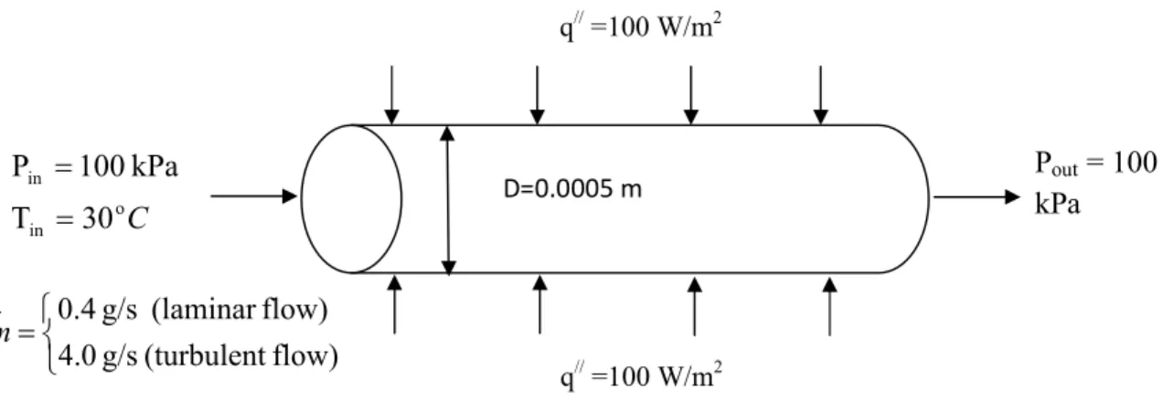
SIMULATION OF SINGLE PHASE FLUID FLOW IN A CIRCULAR
GEOMETRY IN ANSYS WORKBENCH 28
The computational domain of circular microchannel is represented in two-dimensional (2D) form by a rectangle and shown in Fig.
MESHING OF GEOMETRY 29
PHYSICAL MODELS 29
MATERIAL PROPERTIES 29
GOVERNING EQUATIONS 30
4.8) Since the microchannel with small radial thickness is placed horizontally, the external body force F is taken as zero. These fluctuations mix transported quantities such as momentum, energy and species concentration, and cause the transported quantities to fluctuate as well. Because these fluctuations can be small-scale and have high frequency, they are too computationally expensive to simulate directly in practical engineering calculations.
Instead, the instantaneous (exact) governing equations can be averaged over time, and averaged across ensembles, resulting in a modified set of equations that are computationally less expensive to solve. In these equations, Gk represents the generation of kinetic energy from turbulence due to the mean velocity gradients. YM represents the contribution of the fluctuating dilation in compressible turbulence to the total dissipation rate. C1ε, C2ε and C3ε are constants.
The bulk mean temperature, Tm,x and wall temperature, Tw,x with distance x from the microchannel entrance can be obtained by doing the thermal energy balance around the microchannel as shown in Fig. To characterize the effect of fluid flow on the thermal behavior of the microchannel heat exchanger Peclet number, Pe is defined as.
BOUNDARY CONDITIONS 33
METHOD OF SOLUTIONS 33
RESULTS AND DISCUSSIONS 34
The heat transfer data show that the inclusion of nanoparticles in water increases the heat transfer coefficient. In the case of laminar flow, both the analytical and CFD results show that heat transfer coefficient increases approximately by 15% magnitude from pure water to 5% nanofluid. As expected, both the tabular data and figures show that heat transfer coefficients in turbulent flow are more than laminar values.
Like laminar heat transfer coefficient, the values of heat transfer coefficients in turbulent flow also increase with increase in nanoparticles concentration. The heat transfer coefficient values for both flow types are found to be independent of axial position. To prove it, Table 4.6 shows the relationship between heat transfer coefficient of water and heat transfer coefficient of nanofluids at different values of Re.
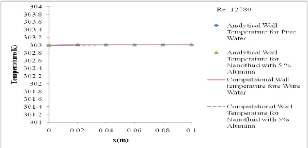
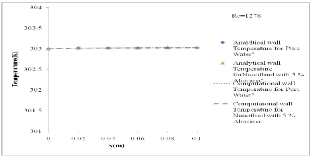
It is clear from the table that the ratio between the heat transfer coefficient of water and the heat transfer coefficient of nanofluids is equal to the thermal conductivity of water and the thermal conductivity of the nanofluid. The investigation of wall temperature variation using water as heating medium in a circular microchannel is done for different values of Reynolds number. It is clear from the figure that with a higher Re there is less variation in the wall temperature than with a lower one.
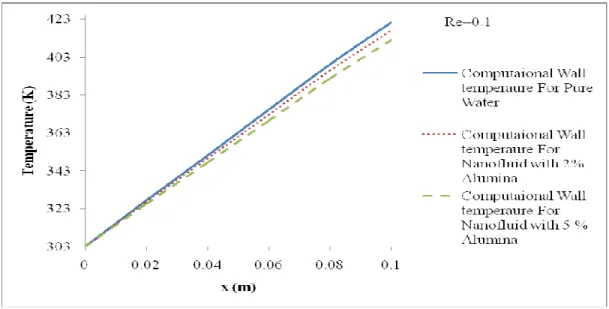
The effect of Reynolds number on the variation of wall temperature with axial position is presented in Table 4.8 and also in Fig. The variation of wall temperature of water with radial position (Y) at different values of X and at different values of Re is shown in Fig. This happens because convective heat transfer rate dominates over conductive heat transfer rate even at Re = 0.1 for which also Pe >> 1.
At Re = 0.1, the temperature increases with the increment X, and the possible explanation is given under discussion of the velocity profile of water in the exchanger.
CONCLUSIONS 49
The wall temperature changes at different power inputs along the micro channel are shown in Fig. Fluid flow and heat transfer at the micro and meso scales with application to heat exchanger design. Effect of flow and thermal regime development on momentum and heat transfer in microscale heat sink International Journal of Heat and Mass Transfer.
Experimental investigation of convective heat transfer of nanofluids at the inlet region under the laminar flow region.
MODELING OF SINGLE PHASE FLUID FLOW IN RECTANGULAR
GEOMETRY OF THE COMPUTATIONAL DOMAIN 52
MESHING OF THE COMPUTATIONAL DOMAIN 53
PHYSICAL MODEL 53
FLUID PROPERTIES 53
ASSOCIATED EQUATIONS 54
BOUNDARY CONDITIONS 55
SOLUTION METHODS 56
Higher values of the heat transfer coefficient are obtained at the entrance region of the microchannel, while lower values are obtained at the exit region for all fluid properties. For example, the heat transfer coefficient at the entrance region and the exit region is 16.837 W/m2.K and 5.811 W/m2.K respectively at a heat input of 100 W for pure water. Calculated temperatures and heat transfer coefficients were found to be in close agreement with the analytical values.
Application of efficiency-NTU relationship to parallel flow microchannel heat exchangers subjected to external heat transfer.
RESULTS AND DISCUSSIONS 56
CONCLUSIONS 74
Microchannel heat sink with suspension of water with microencapsulated phase change material: 3D numerical study.
CONCLUSIONS AND FUTURE SCOPE OF WORK
FUTURE SCOPE OF WORK 76