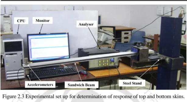
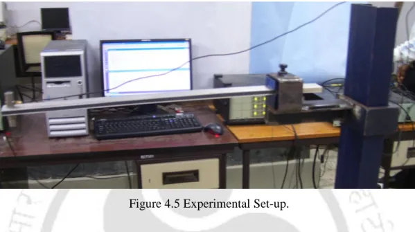
An experimental setup was established to investigate the dynamic properties of the embedded MRE. The regions of instability of the sandwich beam subjected to periodic axial loading are found to vary with different system parameters and boundary conditions.
Dynamic Analysis of MRE-based Sandwich Beam with
Stability of MRE-based Sandwich Beam Subjected to Time
Dynamic Analysis of Rotating and Non-rotating MRE Embedded
Dynamic Analysis of Sandwich Beam with Composite Skins
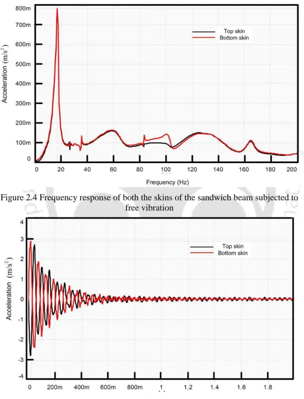
Experimental Vibration Analysis of Magnetorheological
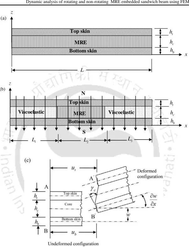
64 Figure 3.2 Schematic diagram of the MRE embedded viscoelastic core. sandwich beam subjected to time-varying magnetic field and.
Introduction and Literature Review
Introduction
To actively reduce the vibration of the system, both static and time-varying magnetic fields were used. The motivation of the present work is highlighted in section 1.4 and the objective of present work is given in section 1.5.
Literature Review
- Materials and Material Properties of Sandwich Beam
- Magnetorheological elastomers
- Sandwich Beam Theories
- Free and Forced Vibration of Sandwich Beams
- Stability Study of parametrically Excited Sandwich Beams
- Magnetorheological Material Based Adaptive Sandwich Structures
Kaleta et al., (2011) presented a method to fabricate the magnetorheological elastomers (MRE) with a thermoplastic elastomer matrix. Wei et al., (2006) studied the vibration control of a flexible rotating sandwich beam with electrorheological (ER) core.
Summary of Literature Review
They studied the parametric instability regions of the sandwich beam subjected to periodic axial loading. It is observed that no research has been conducted on MRE embedded sandwich beam with time varying magnetic field.
Motivation of the Present Work
A static magnetic field has been considered in all previous studies on embedded sandwich beam MRE. Recently, few researchers have attempted to study the free and forced MRE vibrations of an embedded sandwich beam.
Objectives of the Present Work
To study the dynamic properties and stability of MRE core rotating sandwich beam using finite element method. To develop experimental setup to study the vibration characteristics of MRE embedded sandwich beams.
Organisation of the Thesis
To study the dynamic behavior and stability of sandwich beam with MRE flexible core and non-conductive composite skin. In addition to these, the dynamic characteristics and stability of a rotating sandwich beam with an MRE core are also investigated in this chapter.
Dynamic Analysis of MRE-based Sandwich Beam with Conductive Skins under Various Boundary Conditions
Introduction
Mathematical Modeling
Solving the equations (2.3) and (2.4), the expressions for the axial displacement of the top and bottom skins can be given by When the skins of the sandwich beam vibrate in a magnetic field, the eddy current is induced in the skins.
Approximate Solutions
Here it can be noticed that the Heaviside function is used to take care of the location of the MRE part in the sandwich beam core. In contrast to sandwich beam analysis using higher-order theory (Dwivedy et al., 2009), four times fewer no equations need to be solved to find the system response using the proposed approach. Unlike the work of Howson and Zare, (2005), where a sixth-order differential equation is solved, or the work of Banerjee et al., (2007), where a tenth-order differential equation is solved to obtain the natural frequencies of the system, in this paper a fourth-order differential equation is solved for the dynamic analysis of the system.
Using MATLAB, a code was developed to determine the system response and regions of instability of a sandwich beam with different boundary conditions.
Results and Discussions
- Validation of the Assumption
- Comparison of Natural Frequencies
- Free Vibration Response of MRE Embedded Sandwich Beam
- Instability Regions of MRE embedded Sandwich Beam with Periodic Axial Load
- Comparison of Instability Regions Obtained Using Higher Order Theory
- Application of Present Theory for Passive and Active Vibration Reduction of Sandwich Beam
The time response of an MRE-embedded simply supported sandwich beam has been discussed in the next subsection. Considering only the viscoelastic core (i.e. the core without MRE patch), the solid line shows the parametric instability regions for the first three modes of the sandwich beam for the main parametric resonance. For the system parameters taken, the sandwich beam with a fully MRE core appears to be stable.
Thus, by changing the length of the MRE patch, the vibrations of the sandwich beam can be passively damped.
Summary
For a given sandwich beam, the decision whether to choose active or passive vibration reduction depends on the action amplitude and frequency of the axial load. If the point corresponding to the operating amplitude and frequency is in the unstable region for a given magnetic field range, then the designer should opt for passive vibration control by suitably choosing the correct size and material of the sandwich beam and the existing beam to be replaced with the new one. But if it is possible to have the point corresponding to the operating amplitude and frequency outside the unstable region for a given magnetic field range, by applying a suitable magnetic field one can actively control the vibrations of the system.
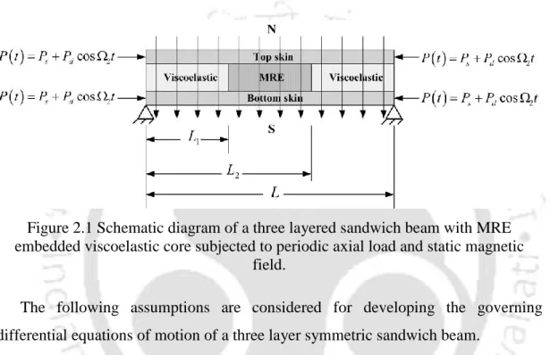
Stability of MRE-based sandwich beam subject to time-varying magnetic field and periodic axial load.
Stability of MRE-based Sandwich Beam Subjected to Time Varying Magnetic Field and periodic Axial Load
Introduction
Mathematical Modeling of the Sandwich Beam Without Periodic Axial Load
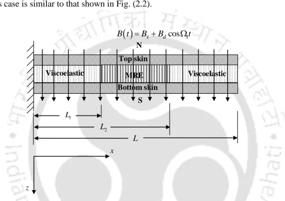
Here Bs is the amplitude of static magnetic field, Bd and 1 are the amplitude and frequency of the dynamic magnetic field respectively. The deformed and undeformed cross-sections of the sandwich beam in this case are similar to those shown in Fig. To obtain the solution of the temporal motion equation (3.4), the first-order method of multiple scales (Nayfeh and Mook, 1979) was used here.
Neglecting the expression O(3), one can write the expression for transition curves of the second order expansion when 1 1 as.
Mathmatical Modeling of the Sandwich Beam with Time Varying Magnetic Field and Periodic Axial Load
- Principal parametric resonance case ( 2 2 and 1 away from 1)
- Simultaneous resonance case ( 1 1 and 2 2 )
One can obtain the expression for the transition curves by finding the value of from the above two equations. Since the expressions for the coefficients 1 and 2 are given in the section above, the expression for the coefficients is 3. In this case, one can use the detuning parameter to express the proximity of frequencies for the resonance conditions, such as. 3.27) and eliminating the secular terms or terms with small divisors.
Following the method similar to that described in sections 3.3.1 and 3.3.2, the expression for the transition curves can be given by.
Numerical Results and Discussions
- Instability Regions of a Sandwich Beam Subjected to Time Varying Magnetic Field for Simple Resonance Case
- Instability Regions of a Sandwich Beam Subjected to Time Varying Magnetic Field and Periodic Axial Load
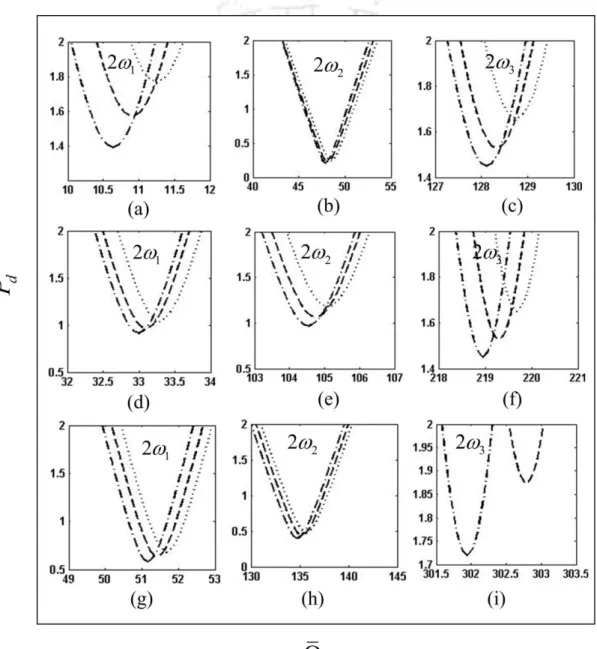
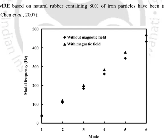
3.6 (a) shows the time response for the transverse displacement of a sandwich beam with an embedded MRE core. 3.7 (a), it can be observed that as the percentage of iron particles increases, the regions of instability decrease, as the core loss factor and shear modulus of MRE increase with increasing magnetic field. Similar to the simply supported case, increasing the skin thickness improves the stability of the system.
It is observed that with increase in magnetic field, the stability of the system improves.
Summary
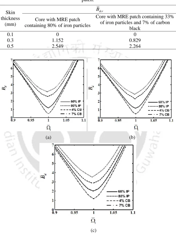
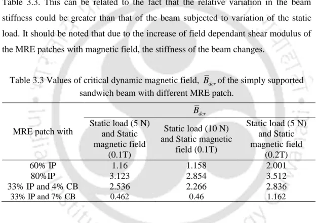
It is also noticeable that for sandwich beams with an MRE patch containing 80% iron particles, the value of Bdcr decreases by 3.67% with a dynamic load of. Dynamic analysis of rotating and non-rotating MRE embedded sandwich beam using finite element method.
Dynamic Analysis of Rotating and Non-rotating MRE Embedded Sandwich Beam using Finite Element Method
Introduction
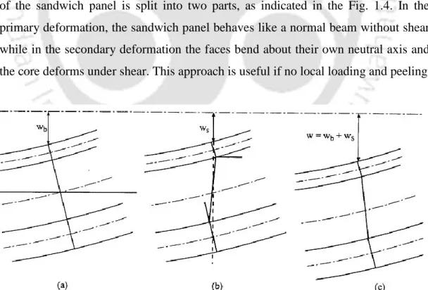
The strain energy contributions due to bending and extension of the top and bottom skins of the sandwich beam, Utb, can be expressed as. It has been assumed that the normal stress of the core is negligible and that the core deforms only by shear. The total strain energy U of the sandwich beam is expressed as the sum of the energy due to the upper, lower and middle layers, such that.
UUtb UcUm (4.9) The total kinetic energy of the sandwich beam can be obtained by adding the kinetic energy due to the transverse displacement of all layers, the axial displacements of the upper and lower skins and the rotation due to the shear stress of embedded viscoelastic core MRE.
- Dynamic Stability Analysis
To analyze the stability of sandwich beams, the method developed by Bolotin, (1964) is used to obtain the correlation for the dynamic instability of the system. Considering the damping effect of the MRE on the sandwich beam, the equation of motion can be rewritten as. periodic motion of the system is usually the limiting case of vibrations with infinitely increasing amplitudes. Therefore, it is important to study the dynamic instability of the system and determine the limits of the dynamic instability regions.
The above equation is used to find the boundaries of parametric instability regions of the system.
Dynamic Model of a MRE Cored Rotating Sandwich Beam
- Dynamic Stability Analysis
Work done by a rotating beam due to the centrifugal forces can be expressed as (Lin and Chen where, Nh is the rotation speed in rad/sec, A is the cross-sectional area of sandwich beam, is the mass density of the system and x is the radial stress created by centrifugal forces acting on any section at a distance x from the left side of the element: Here N is the total number of elements of the sandwich beam and n is the number of elements before and not including the element under consideration To reduce the size of the matrix the Guyanese reduction method as discussed in section 4.3 is used and the Eq.
The modal frequencies of the system are obtained by finding the real part of the square root of eigenvalues of M 1 K.
Results and Discussions
- Dynamic Properties of Sandwich Beam
- Dynamic Stability of the Various Configurations of Sandwich Beam
- Numerical Results and Discussions of a Rotating Sandwich Beam
This is due to the fact that the stiffness of the sandwich beam increases with the increase in the length of the MRE patch. Furthermore, it is possible to actively increase the stiffness of the sandwich beam using a magnetic field. 4.21 (a) and (b), the regions of instability decrease with increasing magnetic field for all locations of the sandwich beam.
It can also be observed that the width of the instability region decreases as the rotation speed increases. It can also be observed that the width of the instability regions increases with an increase in the entry angle. It can also be observed that the width of the instability regions increases with the increase of the static load factor.
Summary
Dynamic Analysis of Sandwich Beam with Composite Skins and Flexible MRE Core using FEM
Introduction
Finite Element Formulation
- Dynamic stability analysis
The DOF includes the transverse, axial and rotational displacements of the top and bottom composite surfaces of the sandwich beam. The kinetic energy can be rewritten in nodal displacement variables for an element of length le as follows:. 5.17) the governing equations of motion for the sandwich beam element in the finite element form are derived for the following load conditions. The work done by the transverse harmonic force Qt due to transverse displacement of the top skin can be written as,.
The work done by the periodic axial load P t due to independent transverse displacements of top and bottom skins can be written as,. and are the static and dynamic load factors, respectively. 5.24) can be rewritten in nodal displacement variables for an element of length le as follows:.