I have submitted this dissertation to the Center for Nanotechnology, Indian Institute of Technology Guwahati for the award of the degree of Doctor of Philosophy. The dissertation work titled "Engineering Devices with Functional Nanomaterials" by Sailapu Sunil Kumar, a PhD student at the Center for Nanotechnology, Indian Institute of Technology, Guwahati, has been confirmed to be an authentic record of the research work being done by him.
A BSTRACT
DPBF: 1, 3 – Diphenylisobenzofuran SPR: Surface Plasmon Resonance SSC: Physiological Sodium Citrate EMF: Electromotive Force SWG: Standard Wire Diameter EDX: Energy Dispersive X-rays.
ABSTRACT
1.1 | Fabrication of Nanomaterials
The second approach, i.e. the bottom up fabrication method develops nanostructures through the systemic organization and assembly of atoms, molecules and even nanomaterials. Highly controlled chemical synthetic routes, deposition techniques, self-assembly, etc., are often used for bottom-up fabrication of complex architectures.
1.2 | Functional Attributes of Nanomaterials
This style of using building blocks to achieve desired configurations is highly promising as it offers advantages such as fewer defects, no crystallographic damage, homogeneous chemical composition, small dimension structures close to atoms and no waste or unused materials.[3, 5] Among to the top approaches are still in a nascent stage of development and the objects are not mass-producible as in the silicon technology. Considering each of their meanings, a strategic combination of both these approaches, i.e. however, 'hybrid methods' result in the desired outputs.[4].
1.3 | Technological Advancement
1.4 | Autonomous Motion of Micro/Nano bots
Feynman, "there is a lot of room at the bottom" and it is necessary to exploit this true potential of these fundamental properties to build efficient systems. The result of such an achievement would be the ability to build complex systems and devices to reconfigure electronics in real time, optimize computing power, deliver drugs, destroy toxic materials, target therapy, repair biological components, harvest energy, act on body parts, deliver cargo, etc. [13, 16].
1.4.1 | Biological Motors
1.4.2 | Hybrid nanomotors – Bionanomachines
The dominant physical forces that arise as a result of design limitations in devices also affect the functionality of biological motors and, in turn, can lead to reduced or loss of activity.[13, 16].
1.4.3 | Synthetic Motors
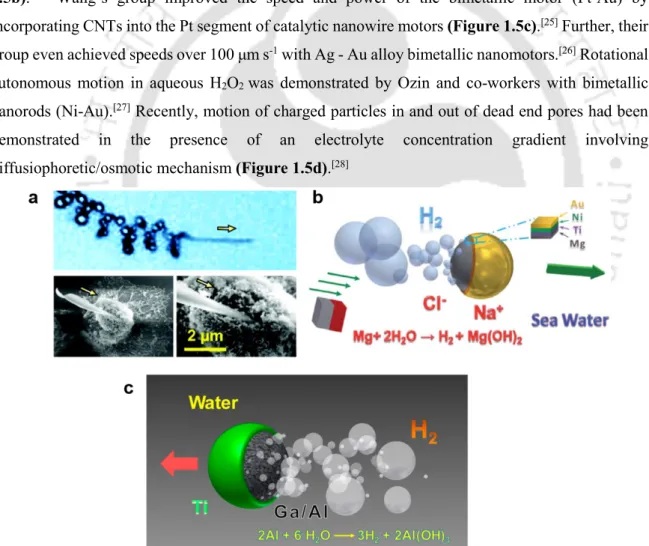
Self-electrophoretic motors, driven by an electric field generated by the motor in a liquid, were demonstrated by Mallouk and Sen in 2004 (Figure 1.5a). Their motor was made of bimetallic nanorods (Pt on one end, Au on the other). end). Janus micromotors based on Mg NPs were shown to be propelled by hydrogen bubbles in seawater. These engines were also magnetically controlled by the incorporation of Ni and promise applications in environmental oil remediation (Figure 1.6b).
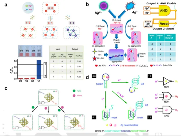
Some logic implementations mentioned above are shown in Figure 1.8. a, b) Colorimetric implementation of AND logic based on Au NPs with ions as input.[57-58] (c) NAND logic for nitrite detection using luminescent Au NCs. (d) Multiple logic gates using fluorescent Ag NCs.[62]. Luminescence-based logic gates (OR and XOR) based on the dual aptamer strategy was achieved using the high photoluminescence quality of QDs.[60] Luminescent Au NCs functionalized by bovine serum albumin (BSA) were used in the detection of nitrite ions through the construction of NAND logic gate (Figure 1.9c).[61] Multiple logic structures were also developed using ion-tuned fluorescent DNA/Ag nanoclusters (NCs), with K+ and H+ as two inputs (Figure 1.9d).[62].
1.6 | Medical Devices
INHIBIT and XOR) were successfully demonstrated (Figure 1.9b).[58] Furthermore, EN, INHIBIT, and IMPLICATION logic was achieved with the coordination chemistry of cytosine-Ag+-cytosine (C– .. Ag+–C) and dissimilar adsorption properties of ssDNA and dsDNA-modified AuNPs.
1.6.1 | Diagnostics
Specific contrast agents and radiopharmaceuticals given to the patient to perform molecular imaging of the biomarkers responsible for disease occurrence were made with nanomaterials.[80] Also specialized techniques such as vibration ultrasound, nuclear imaging, MRI (magnetic resonance imaging), X-ray imaging have been developed with their specific imaging modules and contrast agents.
![Figure 1.10. (a) Field-effect transistor (FET) based biosensor. [72] (b) Block diagram of DNA Chip](https://thumb-ap.123doks.com/thumbv2/azpdfnet/10515156.0/25.892.164.783.223.720/figure-field-effect-transistor-based-biosensor-block-diagram.webp)
1.6.2 | Therapy
1.7 | Opportunities and Challenges
However, in order to achieve significant growth in the development of devices using these nanomaterials, there are certain areas that need improvement. The current thesis is an attempt to address the above issues and design devices using the properties of nanomaterials.
1.8 | References
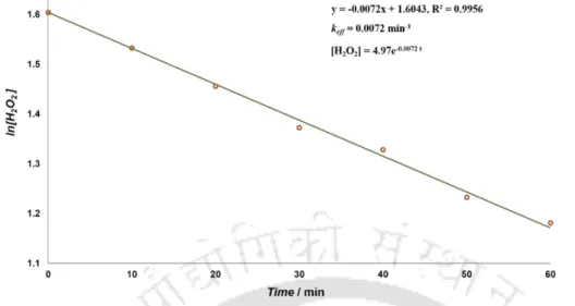
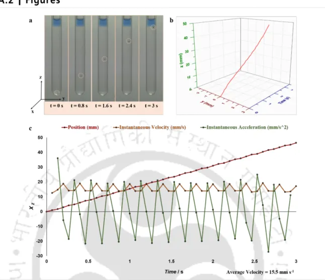
The Pd NPs catalytically decomposed H2O2 to generate O2, leading to buoyancy-driven vertical movement of the particle, while the micromagnet induced emf during the flight. The experimental design also allowed for periodic vertical movement of the bot until the fuel was exhausted.
2.1 | Autonomous Signal Generator
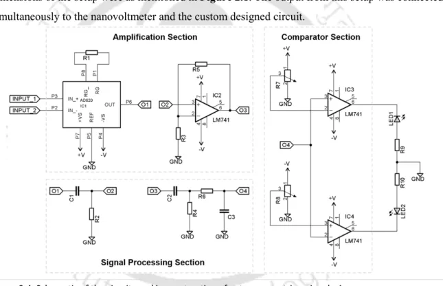
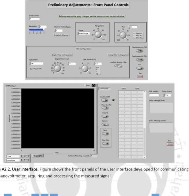
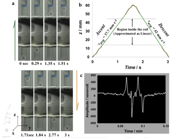
The terminals of the copper coil from the experimental setup were connected to the nanovoltmeter (2182A, Keithley) to measure the generated signal. When the bot comes out of the coil at the other end, the flux changes again, inducing a different signal, but with opposite polarity (also shown schematically in Figure 2.1b).
2.2 | Autonomous Triggering Device
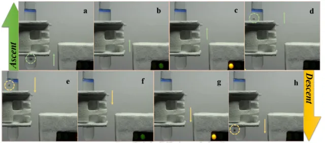
The device was built by connecting the output of the autonomous signal generator to the circuit. a - d) Ascent Period: The bot, driven by mobility, generated a trigger with opposite polarities, turning on the green and then the yellow LEDs respectively. e - h) Descent period: The bot travels down (after popping the bubble) due to gravity flashing the LEDs again in the same way. The simultaneous motion and voltage generation can be captured along with the illumination of the LEDs (green and orange) in the up and down flights of the robot (Figure 2.5; Appendix A, movie A2.3).
2.3 | Theoretical Deductions
It is clear that from above the speed of the bot depends on the buoyancy force, the rest remaining constant. The faster the robot moves in a linear direction without change in orientation, the shorter the time period and the stronger the signal (Figure 2.6c).
2.4 | Concluding Remarks
The spatial (Figure 2.6b) and temporal patterns (Figure 2.6c) of the signal as it crosses the origin are of an alternating type. Further, if the orientation of the bottom changes during flight, it affects the rate of change of flux through the coil accordingly, resulting in the generation of a signal of corresponding strength and polarity.
2.5 | References
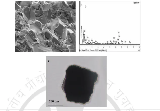
TEM analysis of Pd NP-coated microspheres. a) TEM image of a bead coated with Pd NPs. The magnet fragment (Figure A2.7) used for the experiment was characterized to confirm its important properties.
This is based on the reversible change in luminescence of NCs in response to changes in pH, metal ion concentration and temperature. Au NCs, upon excitation at 300 nm, show emission of different wavelengths and intensities, depending on the pH of the medium (as indicated in the legends).
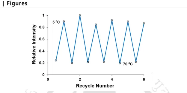
3.1.2 | Temperature Sensor
The charge transfer of the ligand to the metal has been reported to affect the emission behavior of NCs.[21] Furthermore, a similar interaction with the amine and carboxyl groups of chitosan would also affect the emission as a function of the pH of the medium.
3.1.3 | Metal Ion Sensing
The results also indicated that human blood serum also quenched the luminescence (Appendix B, Figure B3.2), possibly due to the presence of metal ions. Further experiments with external addition of Cu2+ to blood serum showed quenching and recovery of luminescence similar to that observed in aqueous medium (Appendix B, Figure B3.3).
3.2 | Logic Systems with Au NCs
The distribution of clusters in the human blood serum and their reversible luminescence properties similar to aqueous medium indicated their possible use in human physiological conditions with wider implications.
3.2.1 | Tri State Buffer
Finally, in the third structure the array is operated at pH 7.0 with the copper ion selected as input as shown in Figure 3.5c. In the absence of copper ion (input logic 0), the array exhibits its natural luminescence at 612 nm (output logic 1) providing a negation of the input signal.
3.2.2 | OR Gate
In the first of the tri-state buffers, the Au NCs can be initially maintained at pH 7.0. Then by selecting the base pH (pH = 8.0) and the lower pH (pH = 3.5) as input, which resemble logic 0 and 1 respectively, the answers are obtained in the same way (output) in terms of logic, as shown in Figure 3.5b.
3.2.3 | Decoder
As depicted in Figure 3.5a, at 70 ºC (input logic 0) with control input active, the intensity is low (output logic 0) in contrast to the response at 5 ºC (input logic 1) where the luminescence intensity is high (output). logic 1). Furthermore, as the results of the experiments with Cu2+ ions in human blood serum indicate (reported above), the three-state logic operations can potentially be performed in physiological conditions, which provides additional advantage of using the biocompatible clusters. a) OR logic operation: The clusters at pH 8, with pH and temperature as the inputs exhibit logic OR operation with their luminescence relatively high in three cases as shown.
3.2.4 | Lock and Key
The proposed decoder has four different luminescent output combinations of wavelength and intensity for corresponding input combinations of pH and temperature.
3.2.5 | Cascading to Higher Levels
The changes are clearly observable in terms of intensity and wavelength, which represent the system as a data decoder. This three-level operation execution describes not only the system's ability to achieve low-order functions, but also can be operated hierarchically with appropriate design and construction.
3.3 | Concluding Remarks
3.4 | References
The components of the portable device for gene expression studies are shown in the figure. The luminescence of the Au NCs was proportional to the amount of template present, i.e., the DNA concentration.
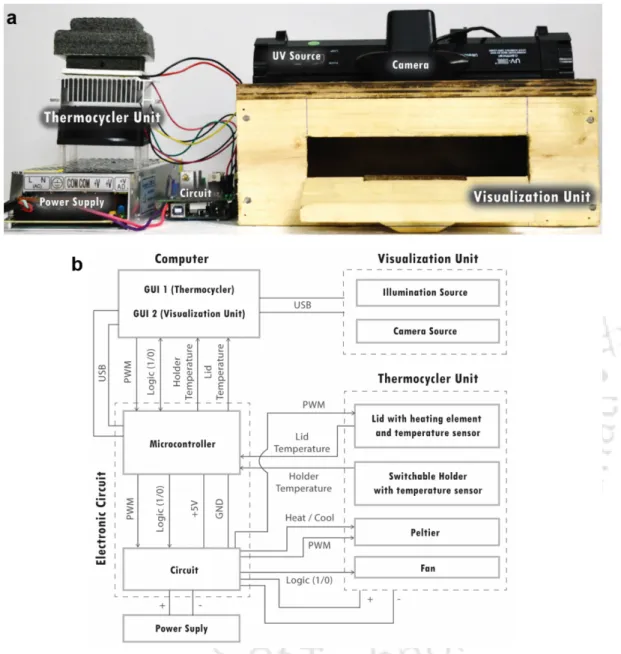
4.1 | Description of the Device
The Thermocycler unit is responsible for performing the RT-PCR process, array-based experiments and the synthesis of Au NCs – the signal generating agents in both liquid and on membrane. Controls – The controls include actions such as starting a process, stopping a process, and closing the application.
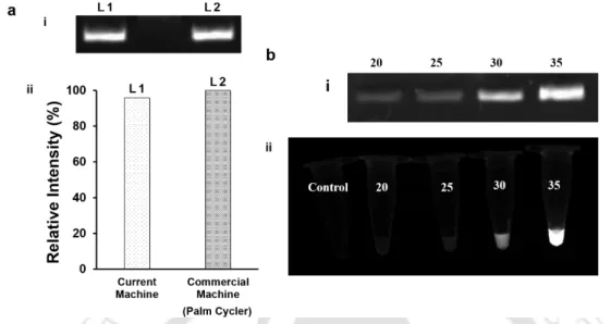
4.2 | Reverse Transcriptase Polymerase Chain Reaction
Amplification of DNA with the device and Au NCs as signal generating means for PCR amplicon quantification. a) The β-actin gene was amplified using specific primers in the present device and commercial machine. This results in the synthesis of Au NCs in proportion to the amount of PCR amplicon present.
4.3 | Array based Gene Expression Studies
Therefore, Au NCs were successfully used to test the expression of several genes regulating the apoptosis pathway using HeLa cells as a model system. Multiple gene expression study in control HeLa cells and DOX-treated HeLa cells. a) and (b) Grayscale images under UV illumination (254 nm) of Au NCs synthesized on different genes (sheets) in control and treated HeLa cells (respectively).
4.4 | Concluding Remarks
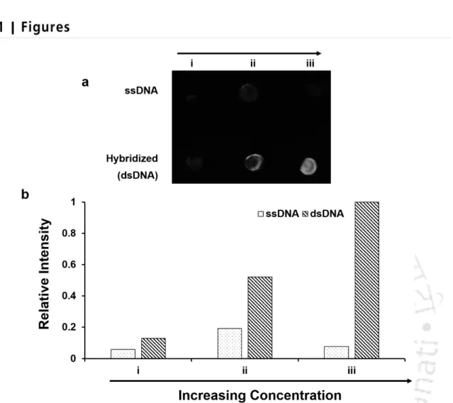
Caspase - 3 was upregulated and BCL - 2 was downregulated relative to the endogenous control β-actin, indicating apoptosis in the case of DOX-treated HeLa cells compared to control HeLa cells. After that, increasing amounts of BCL - 2, BAX, caspase - 3 PCR amplicons ((i) 0.18 μg, (ii) 0.37 μg and (iii) 0.74 μg) were obtained from control cells and cells , treated with DOX, heated and rapidly processed. cooled to give single-stranded products and then hybridized with the capture probes mentioned above.
4.5 | References
After that, Au NCs were synthesized at all points using the thermocycling unit of the device. Au NCs were synthesized at all points using the thermocycling unit of the device and the membrane was imaged on the visualization unit.
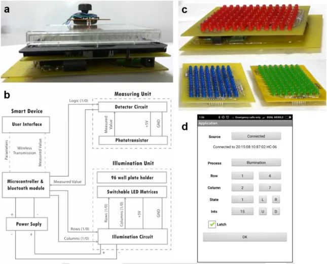
5.1 | Description of the Device
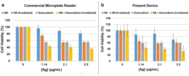
The efficacy of the therapy was monitored through MTT (3-(4,5-dimethylthiazol-2-yl)-2,5-diphenyltetrazolium bromide) and LDH (lactate dehydrogenase) assays using the device. This feature allowed device construction to achieve both PDT-based and colorimetric assays on a single platform.
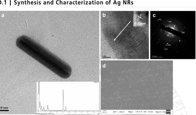
5.2 | Singlet Oxygen Generation with Ag NRs
Software Application: A user application is developed as shown in Figure 5.2d to talk wirelessly to the device via android based smart devices without physically disturbing it. Functional coherence of the device: The simple design and construction, easy to carry, low power consumption (as portable battery) and the possibility of wireless access make the device portable and can be used even in remote places.
5.3 | Combinatorial Therapy with Ag NPs
MTT assay suggested that combination treatment with Ag NRs and DOX resulted in lower cell viability. It was observed that cell death was higher in the case of combination therapy with Ag NRs and DOX (at the same concentration of Ag and DOX).
5.4 | Concluding Remarks
The switchable LED arrays make the device more robust and use the desired array with a specific wavelength for light illumination. One could also make custom LED arrays and integrate into the device without affecting the underlying circuitry.
5.5 | References
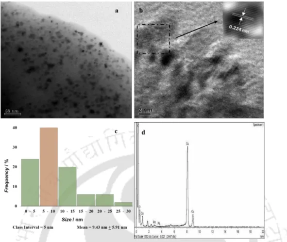
EDX analysis showing the presence of Ag. b) HRTEM images showing the lattice separation of Ag NRs. FESEM (Zeiss - Sigma Advanced Analytical Microscopy) images (Figure D5.1d) also showed the presence of Ag NRs with nm ratio.