ASSESSING THE POTENTIAL OF EMULSIFIED PALM BIODIESEL AS AN ALTERNATIVE TO DIESEL FUEL
A Thesis
Submitted in Partial Fulfillment of the Requirements for the Award of the Degree of
DOCTOR OF PHILOSOPHY
By
BIPLAB KUMAR DEBNATH
DEPARTMENT OF MECHANICAL ENGINEERING INDIAN INSTITUTE OF TECHNOLOGY GUWAHATI
GUWAHATI, INDIA
JUNE, 2013
Dedicated to my Parents….
Mrs. Bela Pal (Debnath) and
Mr. Kajal Debnath
whose endless faith and blessings always inspired me to move forward
Declaration
I hereby certify that the work compiled in this dissertation is the outcome of the research work, performed by myself, else stated, under the guidance of Professor Ujjwal K. Saha and Associate Professor Niranjan Sahoo.
Any part of this work has not earlier been submitted for the award of any degree, diploma, associate-ship, fellowship or its equivalent to any University or Institution.
Biplab Kumar Debnath Registration No. 09610305 Department of Mechanical Engineering Indian Institute of Technology Guwahati
Certificate
It is certified that the work contained in the thesis entitled Experimental and Theoretical Routes Towards Assessing the Potential of Emulsified Palm Biodiesel as an Alternative to Diesel Fuel, by Biplab Kumar Debnath (Registration No. 09610305), a student of the Department of Mechanical Engineering, Indian Institute of Technology Guwahati, India, for the award of the degree of Doctor of Philosophy has been carried out under our supervision and this work has not been submitted elsewhere.
Prof. Ujjwal K. Saha Professor
Department of Mechanical Engineering Indian Institute of Technology Guwahati Guwahati – 781039, India
Dr. N. Sahoo Associate Professor Department of Mechanical Engineering Indian Institute of Technology Guwahati Guwahati – 781039, India
Abstract
iesel engines, the most fuel-efficient combustion devices, are widely used in various sectors such as agriculture, transportation and industry. Diesel vehicles are counted up to 40% and 65% of the total vehicles in India and world, respectively. A higher price of petrol in India will cause these numbers to increase further. However, the public has ample disquiet about the emission released by diesel engines. The emissions from diesel engines namely, black smoke, hydrocarbon, nitrogen oxides, carbon, sulfur etc., are often converted into other lethal materials that harm both ecology and human welfare. The most effective means is to trim down the emission level right at its root.
Biodiesel, methyl or ethyl esters of biofuel, is a renewable, ecologically benign fuel and has been regarded as a promising alternative fuel for diesel engines. This is because biodiesel provides superior lubricity, bio-degradability, and low toxicity than diesel. However, oxidized biodiesels forms higher nitrogen oxide (NOX) when burnt in diesel engines. It is seen that exhaust gas recirculation (EGR) can shrink NOX, but rises particulate emission. Again, oxygen enrichment does the reverse. When both of these methods are employed, they raise cost, repairs and added energy supply. Further, lesser calorific value of biodiesel causes lower efficiency than diesel. The abovementioned problems can be suitably resolved by applying a method, emulsification of biodiesel.
In emulsification, two or more immiscible fluids are mixed together such as water and fuel oil. When sprayed through a nozzle, the emulsified fluid is atomized into fine liquid droplets.
Owing to its lower boiling point than fuel oil, water droplets reach their boiling point first after absorbing an ample amount of heat. The vaporized water then blows up the oil layer, forms smaller oil droplets, and raises the oil’s surface to volume ratio. This is known as
“micro-explosion”. As a result, a stronger degree of mixing amid the atomized oil droplets and the surrounding air takes place, resulting improved combustion efficiency. Hence, the fuel intake drops, which in turn, boosts the efficiency. Further, the vaporization of water absorbs heat, which reduces the maximum cylinder temperature, thereby lessening thermal NO emission.
Palm Oil Methyl Ester (POME) esterified form of palm oil is selected to study it in emulsified form. POME has the greatest oil yield per unit land on earth. Because, palm oil has the higher fossil energy balance, i.e., energy produced over energy consumed. Therefore, it possess the lower production expenses relative to other energy crops. Besides, it has higher Cetane number and decent calorific value (39.84 MJ/kg) comparable to its contenders.
POME (C18.07H34.93O2) also has a sizable amount of oxygen bonded in its molecular
D
structure that makes it to burn more intensely. As a result, POME presents a performance close to that of diesel.
Being a fuel of different origin, the standard design parameters of a diesel engine may not be suitable for POME. Therefore, the initial part of the present investigation targets at finding the performance characteristics of 100% POME in a 3.5 kW Variable Compression Ratio (VCR) diesel engine at various combinations of compression ratios (CR = 16, 17, 17.5 and 18) and injection timings (IT = 20°, 23°, 25°, 28ºBTDC). During this study, the engine load is varied from ‘No load’ (0.1 kg) to ‘Full load’ (12 kg) in steps of 20% for each CR-IT combination tested. This test identifies the superior combination of CR and IT for POME run VCR diesel engine compared to neat diesel performance. Later on, the water in POME (WIP) emulsion is tested in a variable compression ratio (VCR) diesel engine. For this, WIP is initially prepared in an ultrasonic bath sonicator and its stability analysis and calculation of droplet diameter is performed. Thereafter, a stable WIP is tested in the VCR engine for above mentioned CR, IT and load variation (with 10% overloading condition too). The performance parameters evaluated are brake power (BP), brake thermal efficiency (BTHE), brake specific fuel consumption (BSFC) and exhaust gas temperature (EGT). The combustion parameters studied are variation of cylinder pressure, ignition delay (ID), peak cylinder pressure (PCP) and net heat release rate (NHRR). The emission quantities recorded are carbon monoxide (CO), carbon dioxide (CO2), nitrogen oxide (NOX) and hydrocarbon (HC). All the measured, calculated and recorded quantities for POME and WIP at different CR-IT combinations are compared with the standard diesel performance (CR=17.5; and IT=23). The superior combinations of CR and IT for both POME and WIP are also compared in between them for qualitative and quantitative assertion.
This is followed by a thermodynamic potential study for the aforementioned test results. It includes the first and second law analysis of WIP and POME run engine for a load where maximum BTHE take place. The focus of the study is to identify the energy and exergy losses through some of the primary processes and locations of diesel engines with respect to CR-IT variations and quantify the maximum amount of energy that can be utilized from the viewpoint of second law. It is found that, the WIP employed, has lesser calorific value than diesel and even lower than POME. Still it is performed more efficiently than POME and even diesel. This is the clear sign of the presence of micro-explosion for emulsified POME. WIP have performed better at 18 CR and 20ºBTDC of IT along with drop in emission quantities.
Keywords: Compression ignition, Variable compression ratio, Injection timing, Biodiesel, Emulsion, Surfactant, Performance, Combustion, Ignition delay, Heat release, Emission
Acknowledgements
hD is although a small part of life; still it teaches us how to live the life in a large scale. It is equally a magnificent and a prodigious training. Apart from acquiring some knowledge about a tiny, part of scientific fraternity, PhD also teaches one, how to talk, to work in a group, to know people and also to make one understandable to others. In this regard, I have also interacted with a number of personalities, without the support of whom, I may not come this far.
Firstly, I will take this opportunity to express my earnest gratitude to my honorific supervisors, Prof. Ujjwal K. Saha and Dr. Niranjan Sahoo, Department of Mechanical Engineering, Indian Institute of Technology Guwahati, India, for accepting me as their PhD student. They have provided me the complete freedom in my research and allowed me to work in my own way. They always have listened to my ideas with patience and constantly motivated to accomplish my goal. I have learnt from them, how to work with enthusiasm, energy, and life, yet remain composed and grounded. It is hard to express my gratitude with only a few words to these two personalities. The best way to express my thanks to them will probably be to follow the lessons I have leant from them throughout my life.
My sincere acknowledgement goes to Prof. D. Chakraborty and Prof. P. Mahanta, former and present Heads of Mechanical Engineering Department. I thank them for their encouragement, guidance, and support from the initial to the final stages of my PhD work. I am also indebted to the members of Doctoral Committee Dr. A. Verma and Dr. C. Somayaji for their precious suggestions about critical issues related to my work. I am also thankful to Dr. S. Kanagaraj, who has permitted me to work in Material Science Laboratory of Mechanical Engineering Department. I will also drive to thank Prof. A. K. Dass, Dr. P.
Muthukumar and Dr. A.K. De for their immense support during the course work.
I would like to thank Scientific Officers, Mr. R. Saikia, Mr. S. Sarma, Mr. N. Borah of Department of Mechanical Engineering, Mr. P. Kalita and Mr. D. Huzuri, of Centre for Energy, for their enthusiastic support for various apparatus purchase and laboratory necessitates. Sincere thanks to Mr. D. K. Saikia and Mr. N. Das for looking into my official papers during the course of my stay.
P
I owe to my senior Dr. B. B. Sahoo to introduce me to the fascinating field of Diesel Engine and Alternative Fuels. Accompanying him in the laboratory and helping him during his experimental works have bestowed me with valuable knowhow and search the objectives of my work. I am also thankful to my colleagues, Mr. B. Bora and Mr. M. Dabi, who have provided me technical assistance during experimentation and helped me to gather data. I am fortunate enough to get ample support from the technicians Mr. J. Saikia, Mr. M. Sarma, Mr.
D. Khaklary, Mr. D. Chetri, Mr. M.K. Baishya, and Mr. C. Banikya, directly or indirectly, to build the experimental setup.
I am also grateful to MHRD, Govt. of India, for providing me financial support through DST to attend and present a technical paper in ASME 2011 International Mechanical Engineering Congress & Exposition, held at Colorado, USA during November 11-17, 2011.
I am also thankful to Dr. M. Eswaran, Dr. R. P. Chopade, Dr. S. S. Mohapatra, Mr. R.
Kumar, Mr. S. Mahto, Mr. C. Shravankumar, Mr. J. Sardar, Mr. A. Ghatak, Mrs. M.D.
Ghatak, Mr. S. Anbarasu, Mr. S. Roy, Mr. R. K. Peetala and many other individuals with whom I have come into contact during my stay in IIT Guwahati. The friendship and unforgettable attachments shared with them has made my life pleasant.
I am blessed to be the son of my parents, with whom I was unable to spend at least 1 month continuous for last 10 years. Their love and support without any complaint or regret has enabled me to complete this Ph.D. My mother once did not inform me that my father had a stroke, as I was preparing for a foreign trip and took every responsibility of my father’s treatment alone. I owe to both of them, whatever I achieve in life. Last but not the least; I am indebted to SRI SRI THAKUR for keeping me capable to counter the tests of life and making my life beautiful. May everyone’s life be anointed and blooms with YOUR blessings.
June 2013
Guwahati, India Biplab Kumar Debnath
Contents
Chapter Title Page
ABSTRACT i
ACKNOWLEDGEMENTS iii
CONTENTS v
NOMENCLATURE ix
LIST OF FIGURES xi
LIST OF TABLES xiv
1
INTRODUCTION 1-81.1 Preface 1
1.2 Alternative Fuels 3
1.2.1 Biodiesel 4
1.2.2 Emulsified Fuel 5
1.3 Emission Control Norms 6
1.4 Objectives 7
1.5 Organization of the Thesis 8
2
LITERATURE REVIEW 9-412.1 Preface 10
2.2 Biodiesel from Palm Oil 10
2.3 Emulsified Fuel 17
2.3.1 Surfactants and HLB Number 18
2.3.2 Types of Emulsion 19
2.3.2.1 Based on Droplet Size 19
2.3.2.2 Based on Phase 20
2.3.3 Emulsion Characteristics 20
2.3.3.1 Surfactant and Hydrophilic Lipophilic Balance (HLB) 20
2.3.3.2 Additives 22
2.3.3.3 Mixing Parameters 23
2.3.3.4 Criteria of Effective Emulsion 23
2.3.4 Effect on Engine Performance 25
2.3.4.1 Brake Power 25
2.3.4.2 Brake Thermal Efficiency 26
2.3.4.3 Brake Specific Fuel Consumption 27
2.3.5 Effect on Engine Combustion 28
2.4.5.1 Ignition Delay and Combustion Duration 28
2.4.5.2 Cylinder Pressure 29
2.4.5.3 Heat Release Rate 30
2.3.6 Effect on Engine Emission 31
2.4.6.1 Oxides of Nitrogen 31
2.4.6.2 Oxides of Carbon 32
2.4.6.3 Hydrocarbon and Smoke 33
2.4 The VCR Engine 34
2.4.1 History 34
2.4.2 Earlier Work on VCR Engine 35
2.5 Recent Work on VCR Engine 35
2.5.1 Effect of Load 35
2.5.2 Effect of Compression Ratio 36
2.5.3 Effect of Injection Timing 37
2.6 Thermodynamic Analysis of Diesel Engine 38
2.7 Scope of Work 40
2.8 Summary 41
3
CHARACTERIZATION OF EMULSIFIED PALM BIODIESEL 42-543.1 Preface 43
3.2 Characteristics of Emulsion 43
3.2.1 Surfactant and Hydrophilic Lipophilic Balance 44
3.2.2 Ratio of Emulsifying Fluids 46
3.3 Emulsified POME Preparation and Stability Study 46
3.3.1 Ultrasonic Bath Sonication Machine 46
3.3.2 Emulsion Preparation Procedure 47
3.3.3 Measurement of Droplet Diameter 48
3.3.4 Stability Study 52
3.4 Summary 54
4
VARIABLE COMPRESSION RATIO ENGINE TEST SETUP 55-474.1 Preface 56
4.2 The VCR Engine Setup 56
4.3 Instrumentations for Measurements 59
4.3.1 Performance Measurement 59
4.3.2 Air and Fuel Flow measurement 59
4.3.3 P- Measurement 59
4.3.4 Temperature Measurement 60
4.3.5 Compression Ratio Variation Control 60
4.3.6 Injection Timing Variation Control 60
4.3.7 Emission Measurement 60
4.4 Experimental Design and Procedure 61
4.4.1 The Neat Diesel Test 61
4.4.2 The Neat POME and Emulsified POME Tests 62
4.5 Summary 63
5
RESULTS AND DISCUSSION: NEAT PALM BIODIESEL RUN ENGINE64-80
5.1 Preface 65
5.2 Performance Analysis 66
5.2.1 Effect of Load 66
5.2.2 Effect of Compression Ratio 68
5.2.3 Effect of Injection Timing 68
5.3 Combustion Analysis 71
5.3.1 Effect of Load 71
5.3.2 Effect of Compression Ratio 71
5.3.3 Effect of Injection Timing 73
5.4 Emission Analysis 74
5.4.1 Effect of Load 74
54.4.2 Effect of Compression Ratio 77
5.4.3 Effect of Injection Timing 79
5.5 Uncertainty Analysis 79
5.6 Summary 80
6
RESULTS AND DISCUSSION: EMULSIFIED PALM BIODIESEL RUN ENGINE81-98
6.1 Preface 82
6.2 Performance Analysis 83
6.2.1 Effect of Load 83
6.2.2 Effect of Compression Ratio 85
6.2.3 Effect of Injection Timing 86
6.3 Combustion Analysis 87
6.3.1 Effect of Load 87
6.3.2 Effect of Compression Ratio 89
6.3.3 Effect of Injection Timing 90
6.4 Emission Analysis 92
6.4.1 Effect of Load 92
6.4.2 Effect of Compression Ratio 93
6.4.3 Effect of Injection Timing 95
6.5 Uncertainty Analysis 97
6.6 Summary 97
7
ANALYSIS AT OPTIMIZED OPERATING CONDITION 99-1067.1 Preface 100
7.2 Performance Analysis 100
7.3 Combustion Analysis 102
7.4 Emission Analysis 104
7.5 Summary 106
8
THERMODYNAMIC POTENTIAL STUDY 107-1278.1 Preface 108
8.2 Thermodynamic Potential of Neat POME 109
8.2.1 Energy Analysis 109
8.2.2 Exergy Analysis 113
8.3 Thermodynamic Potential of Emulsified POME 116
8.3.1 Energy Analysis 118
8.3.2 Exergy Analysis 122
8.4 Summary 126
9
INFLUENCE OF EMULSIFIED PALM BIODIESEL IN DUAL FUELMODE 128-139
9.1 Preface 129
9.2 Setup Modification and Approach 131
9.3 Performance Analysis 134
9.4 Combustion Analysis 135
9.5 Emission Analysis 137
9.6 Summary 139
10
CONCLUSIONS AND FUTURE SCOPES 140-14910.1 Preface 141
10.2 Contribution of the Present Work 141
10.2.1 Neat POME 141
10.2.2 Emulsified POME 142
10.2.3 Comparative Analysis 144
10.2.4 Thermodynamic Potential Study 144
10.2.5 Influence of Emulsified Palm Biodiesel in Dual Fuel Mode 145
10.3 Application Probabilities 146
10.4 Future Scopes 147
REFERENCES 150
A
Equations for Performance and Combustion Analysis 163B
Experimental Uncertainties 168C
Equations for Thermodynamic Potential Study 170List of Publications 172
Nomenclature
Notations Subscripts
A Availability (kW) air Air
BP Brake Power (kW) amb Ambient Condition
Specific Heat (kJ/kg-K) den Density
d Diameter of the Orifice (m) eic Exhaust Gas Inlet to Calorimeter D Engine Cylinder Diameter (m) eoc Exhaust Gas Outlet from Calorimeter
K Number of Cylinder gf Gaseous Fuel
L Engine Stroke Length (m) IG Fuel Ignition m Mass Flow Rate of Air (kg/s) in Input
N Revolutions per Minute (rpm) IN Fuel Injection
p Pressure (bar) lf Liquid Fuel
Q Energy (kW) plf Pilot Liquid Fuel
r Dynamometer Arm Radius (m) we Water Flowing through Engine Jacket R Gas Constant (kJ/kg-K) wic Water Inlet to Calorimeter
Temperature (K) wie Water Inlet to Engine
n Number of Revolutions per Cycle woc Water Outlet from Calorimeter
V Volume (cc) woe Water Outlet from Engine
VE Volumetric Efficiency
W Dynamometer Load (Newton)
Greek symbols
Crank Angle (degree) Efficiency
ρ Density of Fluid, kg/m3 μ Dynamic Viscosity, Ns/m2 γ Ratio of Specific Heats λ Stoichiometric Air Fuel Ratio
Abbreviations
ATDC After Top Dead Centre (degree) PM Particulate Matter BSEC Brake Specific Energy Consumption (kJ/kW-s) POME Palm Oil Methyl Ester BSFC Brake Specific Fuel Consumption (kg/kW-h) rpm Revolution Per Minute
BTHE Brake Thermal Efficiency SI Spark Ignition
BTDC Before Top Dead Centre (degree) SOX Oxides of Sulfur (ppm)
CA Crank Angle (degree) VCR Variable Compression Ratio
CI Compression Ignition WIP Water in POME
CO Carbon Monoxide (ppm) W/O Water-in-Oil
CNT Carbon Nanotube W/O/W Water-in-Oil-in-Water
CPO Crude Palm Oil CR Compression Ratio DI Direct Injection
EGR Exhaust Gas Recirculation EGT Exhaust Gas Temperature (ºC) EA Emulsion Activity
ES Emulsion Stability HC Hydrocarbon (ppm)
HLB Hydrophilic Lipophilic Balance IC Internal Combustion
ID Ignition Delay (degree) IP Indicated Power (kW) IT Injection Timing (degree) JOME Jatropha Oil Methyl Ester LHV Lower Heating Value (kJ/kg) NG Natural Gas
NHRR Net Heat Release Rate (J/deg.CA) NO Nitric Oxide (ppm)
NOX Oxides of Nitrogen (ppm) O/W Oil-in-Water
O/W/O Oil-in-Water-in-Oil
PCP Peak Cylinder Pressure (bar)
List of Figures
Figure no. Caption Page no.
1.1 Global oil supply (India Energy Book, 2012) 2
1.2 Petroleum product consumption (%) in India (Modi, 2012) 3 1.3 The process of micro-explosion (Basha and Anand, 2011a) 5 2.1 Global vegetable oil production for the duration of 1990 to 2006 (Carter et
al., 2007)
13 2.2 Average cost and quantity of vegetable oil production, 2004/05 (Carter et al.,
2007)
13 2.3 Percentage carbon and hydrogen in diesel carbon deposits derived from
diesel–water fuel containing varying proportion of water (Husnawan et al., 2009)
16
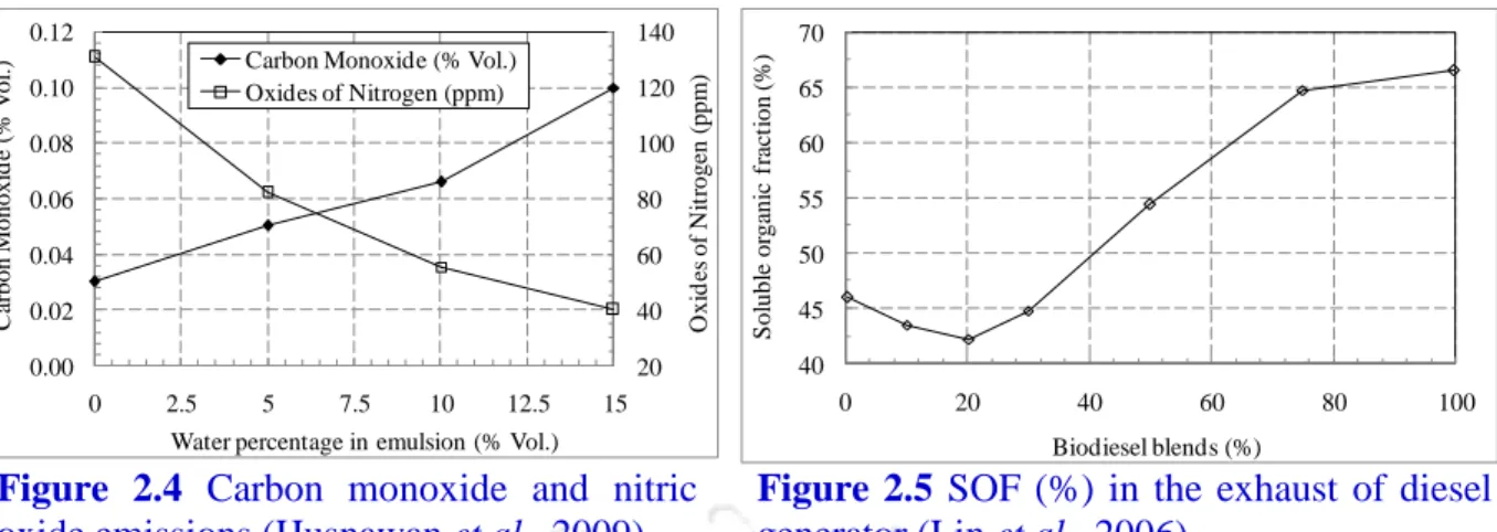
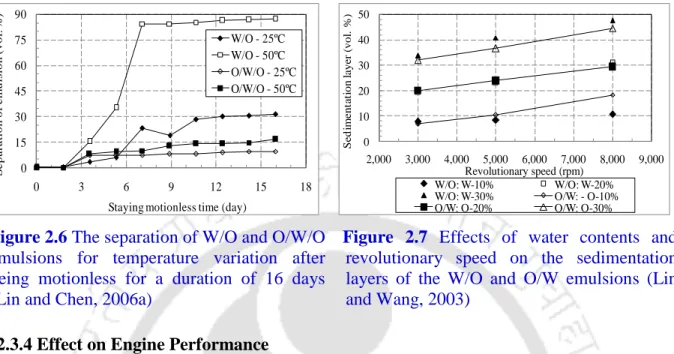
2.4 Carbon monoxide and nitric oxide emissions (Husnawan et al., 2009) 17 2.5 SOF (%) in the exhaust of diesel generator (Lin et al., 2006) 17 2.6 The separation of W/O and O/W/O emulsions for temperature variation after
being motionless for a duration of 16 days (Lin and Chen, 2006a)
25 2.7 Effects of water contents and revolutionary speed on the sedimentation layers
of the W/O and O/W emulsions (Lin and Wang, 2003)
25 2.8 Comparison of brake thermal efficiency with application of emulsified fuel
and water injection in cylinder (Subramanian, 2011)
28 2.9 Variation of brake-specific fuel consumption for CNT and alumina blended
water diesel emulsion (Basha and Anand, 2011a; Basha and Anand, 2011b)
28 2.10 Variation of cylinder pressure for different water quantities and injection
timings for W/O emulsion (Park et al., 2000)
30 2.11 Variation of heat release rate with neat animal fat and its emulsion (Water-
10%, Methanol-10%) (Kumar et al., 2005)
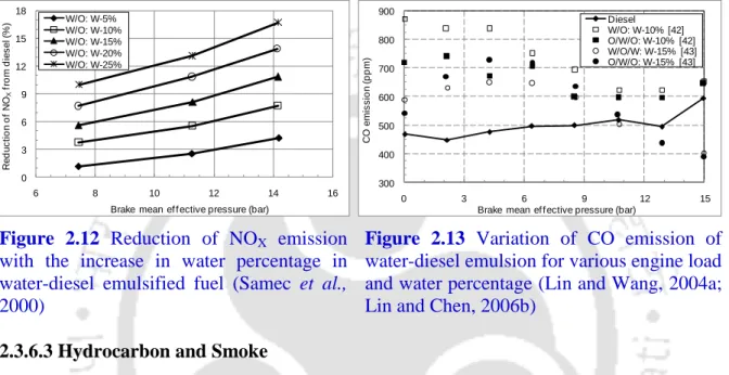
30 2.12 Reduction of NOX emission with the increase in water percentage in water-
diesel emulsified fuel (Samec et al., 2000)
33 2.13 Variation of CO emission of water-diesel emulsion for various engine load
and water percentage (Lin and Wang, 2004a; Lin and Chen, 2006b)
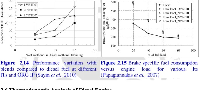
33 2.14 The changes in the performance parameters with the blends compared to
diesel fuel at different ITs and ORG IP (Sayin et al., 2010)
38 2.15 Brake specific fuel consumption versus engine load for various ITs at NPFQ
(Papagiannakis et al., 2007)
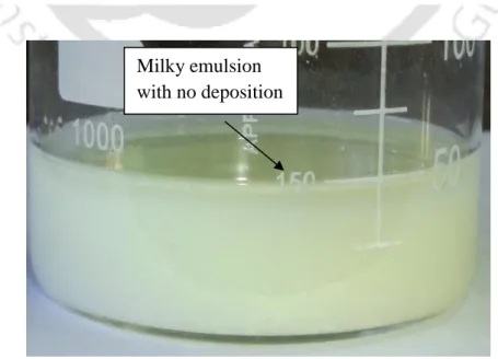
38 3.1 The physical structure of two phase water in oil emulsion 43 3.2 Emulsion sample after 180 minutes (5% WIP with HLB 4.3 and 1%
surfactant)
47 3.3 Variation of mean droplet diameter with emulsification time, surfactant
quantity, HLB and water content
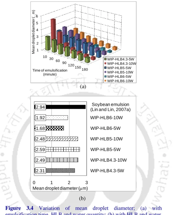
49 3.4 Variation of mean droplet diameter; (a) with emulsification time, HLB and
water quantity; (b) with HLB and water
50 3.5 Photograph of image obtained from optical electron microscope (100X) after
180 minutes of emulsification
51 3.6 Volumetric fraction of layers with time (3% surfactant) 53
4.1 Schematic diagram of the VCR engine setup 58
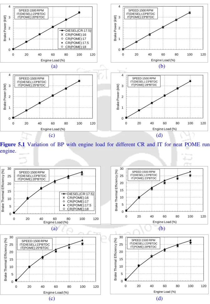
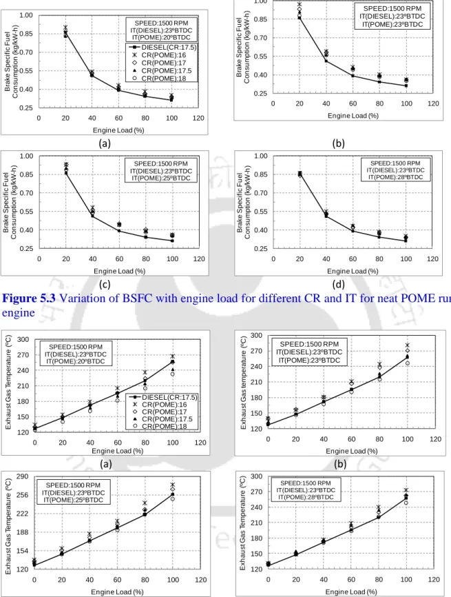
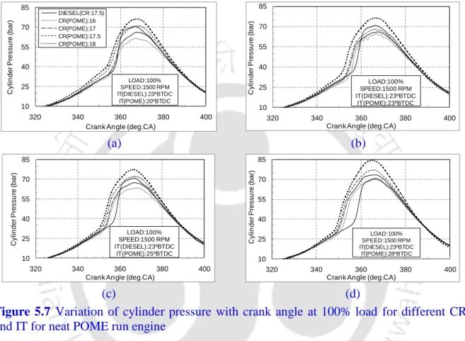
5.1 Variation of BP with engine load for different CR and IT for neat POME run engine
67
5.2 Variation of BTHE with engine load for different CR and IT for neat POME run engine
67 5.3 Variation of BSFC with engine load for different CR and IT for neat POME
run engine
69 5.4 Variation of EGT with engine load for different CR and IT for neat POME
run engine
69 5.5 Comparison of maximum BTHE with CR (IT=23ºBTDC) for neat POME run
engine
70 5.6 Comparison of maximum BTHE with CR and IT for neat POME run engine 70 5.7 Variation of cylinder pressure with crank angle at 100% load for different CR
and IT for neat POME run engine
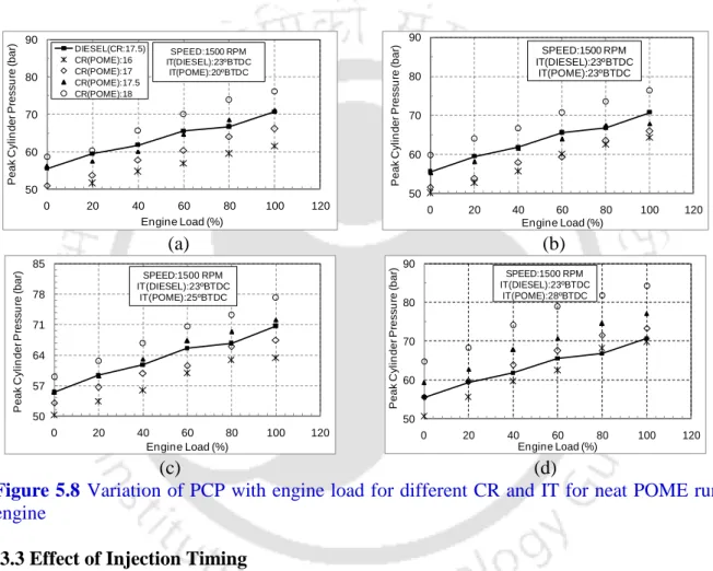
72 5.8 Variation of PCP with engine load for different CR and IT for neat POME
run engine
73 5.9 Variation of ID with engine load for different CR and IT for neat POME run
engine
75 5.10 Variation of NHRR with crank angle at 100% load for different CR and IT
for neat POME run engine
75 5.11 Variation of CO with engine load for different CR and IT for neat POME run
engine
76 5.12 Variation of CO2 emission with engine load for different CR and IT for neat
POME run engine
77 5.13 Variation of NOX emission with engine load for different CR and IT for neat
POME run engine
78 5.14 Variation of HC with engine load for different CR and IT for neat POME run
engine
78 6.1 Variation of BP with engine load for different CR and IT for emulsified
POME run engine
84 6.2 Variation of BTHE with engine load for different CR and IT for emulsified
POME run engine
84 6.3 Variation of BSFC with engine load for different CR and IT for emulsified
POME run engine
85 6.4 Variation of EGT with engine load for different CR and IT for emulsified
POME run engine
86 6.5 Comparison of maximum BTHE with CR (IT=23ºBTDC) for emulsified
POME run engine
87 6.6 Comparison of maximum BTHE with CR and IT for emulsified POME run
engine
87 6.7 Variation of cylinder pressure with crank angle at 100% load for different
CR and IT for emulsified POME run engine
88 6.8 Variation of PCP with engine load for different CR and IT for emulsified
POME run engine
89 6.9 Variation of ID with engine load for different CR and IT for emulsified
POME run engine
90 6.10 Variation of NHRR with crank angle at 100% load for different CR and IT
for emulsified POME run engine
91 6.11 Variation CO with engine load for different CR and IT for emulsified POME
run engine
93
6.12 Variation of CO2 emission with engine load for different CR and IT for emulsified POME run engine
94 6.13 Variation of NOX emission with engine load for different CR and IT for
emulsified POME run engine
95 6.14 Variation of HC with engine load for different CR and IT for emulsified
POME run engine
96 7.1 Variation of performance parameters with load for the WIP run engine 101 7.2 Variation of combustion parameters for the WIP run engine 103 7.3 Variation of emission parameters with load for the WIP run engine 105 8.1 Effect of compression ratio on energy distribution for neat POME run engine 110 8.2 Effect of injection timing on energy distribution for neat POME run engine 110 8.3 Effect of injection timing and compression ratio on peak pressure and peak
heat release rate for neat POME run engine
112 8.4 Effect of injection timing and compression ratio on brake thermal efficiency
for neat POME run engine
112 8.5 Effect of injection timing and compression ratio on exhaust gas temperature
for neat POME run engine
113 8.6 Effect of compression ratio on exergy distribution for neat POME run engine 115 8.7 Effect of injection timing on exergy distribution for neat POME run engine 115 8.8 Effect of injection timing and compression ratio on exergy efficiency for
neat POME run engine
116 8.9 Effect of injection timing and compression ratio on entropy generation for
neat POME run engine
118 8.10 Influence of compression ratio on energy distribution for emulsified POME
run engine
119 8.11 Influence of injection timing on energy distribution for emulsified POME
run engine
120 8.12 Influence of compression ratio and injection timing on brake thermal
efficiency for emulsified POME run engine
120 8.13 Influence of compression ratio and injection timing variation on peak
pressure and peak heat release rate for emulsified POME run engine
120 8.14 Influence of compression ratio and injection timing on exhaust gas
temperature for emulsified POME run engine
123 8.15 Influence of compression ratio on exergy distribution for emulsified POME
run engine
123 8.16 Influence of injection timing on exergy distribution for emulsified POME
run engine
123 8.17 Effect of injection timing and compression ratio on exergy efficiency for
emulsified POME run engine
124 8.18 Effect of injection timing and compression ratio on entropy generation for
emulsified POME run engine
126 9.1 The modified experimental setup for dual fuel study 132 9.2 Performance analysis of WIP-Biogas dual fuel mode 136
9.3 Combustion analysis of WIP-Biogas dual fuel mode 137
9.4 Emission analysis of WIP-Biogas dual fuel mode 138
A1 Variation of gamma with respect to temperature 168
A2 NHRR for diesel, POME and WIP with constant and variable gamma 168
List of Tables
Figure no. Caption Page no.
1.1 Indian Emission Standards for four wheelers (Emission Standards, 2012) 6 1.2 Emission standards for diesel truck and bus engines, g/kWh (Emission
Standards, 2012)
6
2.1 Important research findings by various researcher(s) on different types of biofuels or biodiesels
11
2.2 Oil production and yield of major oil crop in 2006 (Sumathi et al., 2008) 13 2.3 Estimated ranges of fossil energy balance of biodiesel and diesel (FAO,
2008)
13
2.4 Physical-chemical properties of petroleum diesel and palm biodiesel 14
2.5 ID of POME and diesel (Rodríguez et al., 2011) 15
2.6 Some common use of surfactants, HLB ranges and conduct with water (Rosen, 2004; Guo et al., 2006; DOW Surfactants, 2011)
18
2.7 Two and three-phase emulsions 21
2.8 Various surfactants used with quantities and HLBs for emulsion preparation 22 2.9 Various additives used with quantities for emulsion preparation 23 2.10 Type of apparatus, speed and duration of emulsion preparation 24 2.11 Variation of ignition delay and combustion duration with neat animal fat and
its emulsions (Kumar et al., 2005)
29
3.1 Specifications of the surfactants SPAN 80 and TWEEN 80 (Rosen, 2004) 45 3.2 Matrix quantification of the emulsion components (for each 1000 ml
emulsion prepared)
45
3.3 Specifications of the ultrasonic bath sonication machine (Buehler, 1993) 46
3.4 Significant properties of diesel, POME and WIP 54
4.1 The specifications of VCR diesel engine and accessories 57 4.2 The specifications of Testo 350 S/M/XL flue gas analyzer 61 4.3 The experimental matrix for studying emulsified and neat POME in VCR
engine
63
8.1 Results of energy analysis for neat POME run engine 111 8.2 Results of exergy analysis for neat POME run engine 117 8.3 Results of energy analysis for emulsified POME run engine 121 8.4 Results of exergy analysis for emulsified POME run engine 125
9.1 Significant properties of WIP and biogas 131
9.2 The experimental matrix 133
B1 Uncertainties of independent variables 170
B2 Uncertainties of performance parameters 170
vital segment of the growth of any civilization rests on the use of petroleum fuels, in various fields namely, industry, aviation, power production, transportation etc. However, the use of petroleum fuels needs to be reduced. This is because, they have limited potential and produce serious ecological impact. One of the feasible solutions that has got popularity during last few decades is the use of the fatty acid methyl esters, termed as biodiesels, as alternative fuels of diesel. While burnt in diesel engines, biodiesels offer drop of carbonated emissions and no sulfurized emission. However, being oxidized fuels, biodiesels emit nitrogen oxide (NOX) emissions when burnt in diesel engine.
The fuel emulsion can be a potent solution of this problem. The emulsified fuel, sprayed inside the cylinder, gets atomized and undergo “micro-explosion.” If biodiesel is emulsified with water, then evaporation of water will reduce the adiabatic flame temperature and cut the thermal NO and NOX emission. However, the study of emulsified biodiesel is rare in literature. Alongside, the emulsified biodiesel does not have the same properties to that of diesel too. Hence, the use of emulsified biodiesel at standard diesel engine setting will not offer the best performance. Therefore, it is necessary to study and optimize the performance, combustion and emission characteristics of emulsified biodiesel in a diesel engine at varied operating conditions, namely, load, compression ratio (CR) and injection timing (IT). In order to perform this, a bio-origin alternative fuel, palm oil methyl ester (POME), is selected and tested at various CR and IT settings. Moreover, the thermodynamic energy and exergy analyses are executed for both emulsified and neat POME at maximum efficiency condition.
This chapter briefly describes about alternative fuels, especially, biodiesel, emulsified fuel, and various emission norms. Finally, the chapter concludes with the objectives of the present investigation and the layout of the thesis.
CHAPTER 1
Introduction
A
1.1 Preface 2
1.2 Alternative Fuels 3
1.3 Emission Control Norms 6
1.4 Objectives 7
1.5 Organization of the Thesis 8
1.1 Preface
The world-wide increase of energy consumption is drastically increasing day by day. A report published by “The International Energy Outlook in 2011” shows that, energy consumption of the world will rise by around 53% between 2008 and 2035. This is because of the strong economic growth of the two most important developing countries in the world, namely, China and India. The day is not far, when both the countries will alone consume almost half of the projected rise of world energy use. The petroleum and other liquid fuels are the largest energy source world-wide which presently counts at almost 35% (India Energy Book, 2012).
The present (2011) crude oil price is about $110 per barrel which is almost 30% higher than the level at the start of December 2010 on the New York Mercantile Exchange (Winter, 2011). This is expected to rise to $169 per barrel by 2020 and $200 per barrel by 2035. As far as India is concerned, the situation is not good since 2005. This is because the historical growth of oil production of 3% has been stagnated at that time and reduced in the following years (Figure 1.1). Since then, India has become heavily dependent on the oil import which started at $147 per barrel. Report shows that the rise of oil import, only from 2010 to 2011 has cost India almost 20.5 million US$ (25.7%) extra expenditure (India Energy Book, 2012).
Presently, India is importing more than 80% of its fuel needs (Garg, 2012).
OCED: Organization for Economic Co-operation and Development
Figure 1.1 Global oil supply (India Energy Book, 2012)
The high increase of petroleum import is the result of the increase of petroleum product consumption (Figure 1.2). The market share of diesel, one of the primary products of petroleum in India was raised from 35.52% in 2006-07 to 43% in 2011-12, which is alone
2007 2008 2009
Thousands Barrels / Day Middle East
India China
Rest of the World OECD
11.9% in 2011-12 fiscal year (Modi, 2012). The demand of petroleum products is not going to lessen in coming years, because it’s proportional to the urban development rate of nation.
Hence, it is near to impossible for the government to cut down oil imports and thereby cease the huge outflow of currency. Neither petroleum companies can frequently generate new petroleum drilling sites. Therefore, the natural solution of this problem that comes into mind is to try to scratch petroleum intake by means of its suitable alternatives.
Figure 1.2 Petroleum product consumption (%) in India (Modi, 2012)
1.2 Alternative Fuels
The primary expectations from the alternative fuels are generation of power with economical fuel consumption and minor emission of pollutants. Alongside they should be safe enough to handle and store for both stationary and mobile application. An alternative fuel turns out to be pretty attractive to use, when it provides provision for local production and easy distribution through marketing networks. Finally an alternative fuel is acceptable when any combination of engine technology and fuel meets the prescribed vehicular emission norms as far as environmental prospective is concerned (Thipse, 2011).
Alternative fuel also known as non-conventional or advanced fuel can be defined as the fuel that can be utilized in the internal combustion (IC) engines with the exception of diesel or petrol. Principally, the alternative fuels are classified into three categories. The first type take account of petroleum fuels with non-petroleum additives namely ethers. The synthetic liquids that comprise properties comparable to that of traditional petroleum fuels but found
3.6
3.2 2.9
4.58 4.9
0 1 2 3 4 5 6
2008-09 2009-10 2010-11 2011-12* 2011-12**
Growth in use of petroleum products (%)
Year
* : Projected
** : April to February (Actual)
subsequent to treating of gaseous, solid or liquid fuels falls into second type. The last category non-petroleum fuels, namely alcohol, bio-fuels, biogas, hydrogen etc., are obvious choices (Lapidus et al., 2005). In the midst of these the biofuels and biogas have an important role to be present-day scenario of energy crisis. This is because, biofuels, types of liquid alternative fuel, can be produced locally, from renewable sources. This helps to generate employment, thereby supporting domestic economy. This is helpful to shrink down the huge drainage of national currency in the form of petroleum import.
1.2.1 Biodiesel
The concept of using biodiesel, obtained from vegetable oil, as an alternative to diesel is not new. The “diesel engine”, developed by Dr. Rudolf Diesel in 1895 was intended to run on a variety of fuels. In fact, at the World Exhibition in Paris in 1900, his engine was run by
‘peanut oil’ as fuel. Since then, the diesel engine has been periodically modified to run on petroleum based fuel, more specifically diesel obtained from petroleum. Historically, it was the cheapest fuel available (Clean Alternative Fuels: Biodiesel, 2012). At present, the dual crisis of modern era, the depletion of fossil fuel and its environmental constraints mandated people to interchange or alternate the use of fossil diesel.
Biodiesel is a renewable, environmental friendly fuel and has been regarded as a promising alternative fuel for stationary and mobile applications. Biodiesel, produced from animal fat, vegetable oil or waste cooking oil, can be used as the foundation for a clean substitute for fossil fuel in diesel engines, boilers or other combustion equipment. Its additional advantages consist of outstanding lubricity, superior combustion efficiency and low toxicity, among others (Lin and Lin, 2007a). It has a high flashpoint and low volatility, thus does not catch fire as easily as diesel. This increases the margin of safety in fuel handling, transport, and storage. Biodiesel, more or less contains, approximately 10% of oxygen by weight and thus can be considered as a kind of oxygenated fuel. The high oxygen content in biodiesel results in the improvement of its burning efficiency, reduction of PM, CO and other gaseous pollutants (Lin and Lin, 2007b). It can be used in two ways, either directly or blended with other liquid fuels together with diesel. Hence, it is considered as an environmentally friendly alternative fuel or its additive. Some commonly used biodiesels in diesel engines are the methyl esters of jatropha oil, honge oil, sunflower oil, soybean oil, rubber seed oil, rice bran oil, palm oil, etc. Presently a new type of alternative fuel has enticed the researchers around the globe and is called as emulsified fuel.
1.2.2 Emulsified Fuel
Diesel engine generally runs with excess air. As a result, at high combustion temperature nascent oxygen and nitrogen react together to form, NO which subsequently produces NOX. Therefore, researchers around the globe are trying several options to reduce peak combustion temperature without deteriorating engine performance to cut NOX emission. However, most in-cylinder methods adopted do not reduce NOX and soot simultaneously. It has been seen that exhaust gas recirculation (EGR) can reduce NOX emission but increases particulate emission. On the other hand, oxygen enrichment does the reverse. Further, when these two methods are employed together, they increase the cost, maintenance and added energy ingestion (Subramanian, 2011). Therefore, a modest method has to be established to reduce both of these emissions. Emulsification of fuel may be one of the methods which can solve this problem for a long term. This technique enhances fuel efficiency and reduces emission of hazardous pollutants from diesel engines (Crookes et al., 1997). In emulsification, two or more immiscible fluids are mixed together such as water and diesel. This emulsified fluid (water-in-diesel) when sprayed through a nozzle gets atomized into fine liquid droplets. Since the boiling point of water is lower than that of diesel fuel, water droplets reach their boiling point first after it has absorbed sufficient reaction heat. The vaporization phenomenon of water then blows up the oil layer and thereby forms smaller oil droplets which results in an increase of the oil’s surface to volume ratio. This phenomenon is called “micro-explosion”
(Basha and Anand, 2011a). The mixing extent and the contact surface between air and fuel are increased due to micro-explosion, which leads to a significant increase in the burning rate and burning efficiency. The schematic diagram of mico-explosion is shown in Fig. 1.3.
Figure 1.3 The process of micro-explosion (Basha and Anand, 2011a)
1.3 Emission Control Norms
Diesel engines are widely used in a variety of applications, namely, power generation, transportation, agriculture, marine, military, telecommunication generator sets, etc. They are more proficient and resilient than gasoline engines. However, they suffer awful nuisance due to their higher emission of wrongdoer pollutants like CO, HC, SOX, NOX and soot along with the traditional greenhouse gas CO2. In order to trim down this hazardous emission, India has adopted stringent emission norms, which are also updated. The execution program of European Union emission standards in India is demonstrated in Table 1.1. Emission standards in Euro norms for Diesel Truck and Bus Engines are showed in Table 1.2.
Table 1.1 Indian emission standards for four wheelers (Emission Standards, 2012)
Standard Reference Date Region
India 2000 Euro 1 2000 Nation wide
Bharat stage II Euro 2
2001 NCR*, Mumbai, Kolkata, Chennai April, 2003 NCR*, 11 Cities§
April, 2005 Nation wide Bharat stage III Euro 3 April, 2005 NCR*, 11 Cities§
April, 2010 Nation wide Bharat stage IV Euro 4 April, 2010 NCR*, 11 Cities§
* National Capital Region (Delhi)
§ Mumbai, Kolkata, Chennai, Bangalore, Hyderabad, Secunderabad, Ahmedabad, Pune, Surat, Kanpur and Agra
Table 1.2 Emission standards for diesel truck and bus engines, g/kWh (Emission Standards, 2012)
Year Reference CO HC NOX PM
2000 Euro 1 4.5 1.1 8.0 0.36*
2005§ Euro 2 4.0 1.1 7.0 0.15
2010§ Euro 3 2.1-5.45 0.66-0.78 5.0 0.10-0.16 2010§ Euro 4 1.5-4.0 0.46-0.55 3.5 0.02-0.03
* 0.612 for engines below 85 kW
§ Mumbai, Kolkata, Chennai, Bangalore, Hyderabad, Ahmedabad, Pune, Surat, Kanpur and Agra
However, no matter what the emission standards implemented, the rate of increase in the vehicles both in the developed and developing nations cannot stop the rate of increase in environmental effluence single-handedly. The immediate solution of this problem may be the trim down with the substitution of diesel fuel by their alternatives.
1.4 Objectives
In the present investigation, a bio-origin alternative fuel, palm biodiesel, which is a Methyl Ester of Palm Oil (POME), is selected to study in emulsified form. This is because POME has the greatest oil yield per unit land on earth. The palm oil has the highest fossil energy balance, i.e., energy produced over energy consumed, and the lower production cost relative to other energy crops (Sumathi et al., 2008). POME (C18.07H34.93O2) also has a sizable amount of oxygen bonded in its molecular structure that makes it burn more intensely. This also increases NOX emission, which can be reduced by emulsifying it. A number of people have worked with POME in various types of diesel engines. However, work with emulsified POME as an alternative to diesel is rare. This is maybe because emulsified POME does not possesses the properties of diesel along with a lower heating value (LHV). This causes its inferior performance in standard diesel settings. Hence, there is a need to have a thorough and a systematic study on emulsified palm biodiesel in various engine settings in order to optimize its performance, combustion, and emission characteristics. These types of studies have not been reported in the literature. In view of this, the present investigation is aimed at optimizing the compression ratio (CR) and the ignition timing (IT) of an emulsified palm biodiesel (emulsified POME) run engine to achieve lower emission levels together with an improved or equivalent performance trends than a standard diesel engine. Besides, to locate and estimate the energy and exergy distribution, and destruction for the emulsified POME run diesel engine, a thermodynamic route, has also been considered. This study can play a significant role to understand the enhanced available energy management, of a diesel engine run by emulsified palm biodiesel (Caton, 2012). In summary, the following set of studies, in order, have been performed to arrive at the intended objectives:
Experimentation with neat POME run engine at various CR and IT to optimize its performance, combustion, and emission characteristics as compared to a standard diesel run engine.
Preparation of water-in-POME (WIP) samples and their characterization in order to select the optimum emulsion specification for the engine test.
Experimentation with the WIP run engine at various CR and IT to optimize its performance, combustion, and emission characteristics as compared to a standard diesel run engine
Thermodynamic analysis (energy and exergy potential) of both WIP and POME run engines.
Exploring the potential of WIP as a pilot fuel in a biogas run dual fuel engine.
1.5 Organization of the Thesis
The thesis has been organized by focusing the concentration towards the clean and efficient power production from a diesel engine using emulsified biodiesel. Chapter 1 offers the motivation acquired towards the use of alternative fuel especially emulsified fuel. This is followed by the objective of the dissertation. Chapter 2 introduces the renewable biodiesels especially POME, literatures on emulsified fuels, some earlier, and recent works done in variable compression ratio (VCR) engines, the thermodynamic analysis, and the scopes of work. Chapter 3 elaborates emulsified POME preparation and its characterization. It describe in brief about the surfactants used, hydrophilic lipophilic balance, ratio of emulsifying fluids, emulsion preparation procedure, measurement of droplet diameter and stability study of the emulsified POME. Chapter 4 refers to the VCR engine setup and its different measurement and instrumentation devices. The experimental methods adopted for neat diesel, neat and emulsified POME are also described. Chapter 5 shows the outcome of the experiments done by using POME in VCR diesel engine for a various compositions of load, CR, and IT. The results of the experiments help to optimize the aforementioned design parameters to achieve optimum performance, combustion and emission characteristics of neat POME in the diesel engine. Chapter 6 represents the performance, combustion and emission analysis of emulsified POME tests in VCR mode in view of neat diesel. Chapter 7 has a comparative study between the results obtained at optimized CR and IT combination for neat and emulsified POME test in view of neat diesel test. Chapter 8 explains the thermodynamic analysis covering both first law and second law study of the aforementioned works at a load where maximum efficiency prevailed. Chapter 9 portrays an attempt to check the influence of emulsified palm biodiesel as a pilot fuel in a biogas run dual fuel mode. Chapter10 recaps the key findings of the experiments performed and the future works are proposed.
Literature Review
he diesel engine has walked a long way from its invention, development, and run by peanut oil by Sir. Rudolf Diesel. He initially designed it to run with biofuel. Later on, the production of biofuel had become limited and expensive. Alongside, the increased supply of petroleum diesel made it economical to use. Hence, the following researchers got motivated to redesign the engine for petroleum diesel. The friendship with petroleum fuel with diesel was going good until the decade of seventies, when rise of the price of petroleum fuel and its emission was noticed seriously. Until then people are searching for suitable alternative for petroleum fuel especially diesel due to its almost exponential increase of use.
It has been found that, biodiesel, produced from biofuels can be a suitable alternative.
However, its detrimental issues, namely, lower calorific value and higher nitrogen oxide emission have to be resolved. In this regard, this chapter is dedicated towards the detailed review of the literature performed in the fields of biodiesel, especially POME and its blends with diesel. This is because, as mentioned in the objectives of the present investigation, POME is the carrying fluid of the emulsified fuel. This is followed by a detailed analyses of the emulsified fuels used for diesel engine run. Thereafter, an overview on the history of variable compression ratio (VCR) diesel engine is provided along with some earlier studies executed in it. Then, the recent investigations in VCR diesel engine are also revisited in view of the variation of some engine operating parameters, namely, load, compression ratio and injection timing. The chapter also includes a sincere discussion of literature on the thermodynamic potential study of various types of diesel engine. The special focus is provided on the first and second law studies performed by various researchers using various alternative fuels. Finally, the objectives drawn in the earlier chapter are justified by
identifying the key scopes of works from the comprehensive review of respective literature.
2.1 Preface 10
2.2 Biodiesel from Palm Oil 10
2.3 Emulsified Fuel 17
2.4 The VCR Engine 34
2.5 Recent Works on VCR Engine 35
2.6 Thermodynamic Analysis of Diesel Engine 38
2.7 Scope of Work 40
2.8 Summary 41
CHAPTER 2
T
2.1 Preface
This chapter describes the works performed with liquid alternative fuel. More focus is provided on methyl esters of biofuel, mainly palm oil methyl ester (POME) and its emulsion in diesel engine. Side by side, a detailed review on the performance, combustion and emission studies of variable compression ratio (VCR) diesel engine are also elaborated. The systematic investigation is executed for thermodynamic analysis of diesel engine.
2.2 Biodiesel from Palm Oil
Biodiesel is generally produced from vegetable oils through transesterification. This takes place between vegetable triglycerides and proper type of alcohol. Afterward, two products are left behind, fatty acid methyl esters and glycerin. These methyl esters are called as
‘biodiesels’ and are of biodegrading in nature (Duran et al., 2005). Biodiesel emits less carbon monoxide (CO), particulate matter (PM), soot, unburned hydrocarbons and sulphur oxide (SOX) than diesel (Schmidt and Van Gerpen, 1996). Some of the major works done by using biodiesels are shown in Table 2.1.
Oil palm, an oleaginous tropical plant, has the greatest oil productivity per unit of land on earth (Duarte et al., 2007). Palm oil has dominated the world’s vegetable oil demand because of its versatile uses ranging from food to consumer products, and now as biodiesel. Figure 2.1 shows the global vegetable oil production (Carter et al., 2007). The large supply of palm oil can be attributed to the superiority of palm oil in terms of oil yield (Table 2.2) requiring smaller area of land to produce oil. Besides, palm oil has the highest fossil energy balance, i.e., energy produced over energy consumed (Table 2.3), and the lowest production cost relative to other energy crops (Figure 2.2). It can be used in diesel engine in various ways, namely, crude palm oil (CPO), palm oil methyl ester (POME), and blending of CPO or POME with diesel. Some of the vital works done with palm oil are described as follows.
Assessment of the carbureting eminence of biodiesel, the physical and chemical properties, namely, calorific value, BTHE, distillation curve, viscosity, cloud point, etc., needs to be resolute. Table 2.4 compares the physical-chemical specifications of POME to that of diesel fuel. As reported by Duarte et al. (2007), transesterification of palm oil reduces its calorific value, density, cloud point, and carbon residue as compared petroleum diesel. However, the higher cetane level pays for this drawback. POME produces an efficient burning, making more use of its energy content.
Table 2.1 Important research findings by various researcher(s) on different types of biofuels or biodiesels Researchers Biodiesels Key findings
Agarwal et al. (2008);
Agarwal and Rajamanoharan (2009); Sinha and Agarwal (2010)
Linseed, Rice-bran, Karanja
A blend of 20% Linseed methyl ester with diesel shows higher BHTE and lower smoke emission.
After 100 h of endurance test with 20% Rice-bran oil in diesel shows lower carbon deposit on in- cylinder parts, lower wear on piston rings and cylinder inner surface than diesel. Karanja oil blends with diesel (up to 50%) without as well as with preheating can provide lower emissions and improved engine performance.
Altin et al. (2001) Sunflower, Soybean, Cottonseed
Diesel engine run by Cottonseed biodiesel provides higher engine power, lower CO, CO2 and NOX
emissions than Sunflower or Soybean biodiesel run. However, smoke emission is higher for the Cottonseed biodiesel.
Buyukkaya (2010);
Gokalp et al. (2011)
Rapeseed, Soybean
Running Rapeseed oil in diesel engine increase BSFC, NOX emission; decrease ID, CO, HC and smoke emission as compared to neat diesel. The 5% to 50% blends of Soybean biodiesel with marine diesel produces 74% lower smoke opacity, 12% higher BSFC than diesel in diesel engine.
Banapurmath et al.
(2008, 2009);
Banapurmath and Tewari (2008, 2009);
Honge, Rice Barn, Neem
The maximum BTHE for diesel, Honge, Rice Barn and Neem oils is found to be 31%, 28%, 27% and 26% respectively. Using methyl ester of Honge oil and producer gas in dual fuel mode shows better performance without using the gas carburetor than with gas carburetor. Moreover, Smoke and NOX emission reduces; whereas CO and HC emission increases with Honge oil as pilot fuel. Injection advancement from 19° to 27° improves performance moderately.
Devan and Mahalakshmi (2009, 2010)
Paradise, Eucalyptus, Poon
A blend of 50% Paradise biodiesel with Eucalyptus oil provides a drop of CO (37%), HC (35%) and smoke (49%) emission, along with a 2.4% rise in BTHE. In addition, a little rise in NOX is also reported. Diesel engine run by a blend of 40% Poon biodiesel with diesel shows that smoke, HC and CO were reduced by 65%, 20% and 37%, respectively than diesel run.
Jindal et al. (2010a, 2010b);
Panwar et al.
(2010)
Jatropha, Karanja, Castor seed
Both Karanja and Jatropha biodiesel perform poorer than diesel, whereas former provides higher ID than the later. Both of these fuels produce lower HC, NOX, and smoke emission than diesel. The combined increase of CR and injection pressure for Jatropha biodiesel run engine increases the BTHE, and reduces BSFC and emissions. The best combination is found at CR=18 at an injection pressure of 250 bar. The lower blends of Castor seed biodiesel increased the BTHE, reduced the BSFC and EGT.
Puhan et al. (2005, 2007);
Vedaramana et al.(2012a, 2012b)
Mahua, Sal, Neem
At full load, the methyl and ethyl ester of Mahua oil produce BTHEs of 28.3% and 26.42%, respectively, as opposed to 26.36% for neat diesel. For methyl ester, the highest drops in HC, CO and NOX emissions are obtained as 60%, 67%, and 9% as compared to 49%, 79% and 27% for ethyl ester, respectively. The use of Sal biodiesel in diesel engine cuts CO, HC and NOX by 25%, 45% and 12%, respectively without major change in BTHE.
Raheman and Phadatare (2004);
Raheman and Ghade (2008)
Karanja, Mahua
Up to 40% blend of Karanja oil with diesel is found to increase BP, BTHE and BSFC by 6%, 25%
and 7.4%; whereas reduce CO, smoke density and NOX emissions by 80%, 50% and 26%, respectively. At all CRs (18:1-20:1) and ITs (35-45°BTDC) tested in diesel engine, an increase in the proportion of Mahua oil with diesel, the BSFC and EGT are increased, whereas BTHE is decreased.
The use of Ricardo diesel engine showed satisfactory performance even with neat Mohua oil at various CR-IT settings.
Rakopoulos et al.
(2006, 2008)
Cottonseed, Sunflower,
A blend of 20% Cottonseed oil with diesel provides a similar BTHE, increased BSFC, HC and NOX; reduced CO and soot emissions than 10% or 20% blends of Sunflower biodiesel with diesel.
Kumar et al.
(2010, 2011)
Jatropha The Jatropha biodiesel offers almost a similar performance with diesel mode. However, HC and smoke emissions are increased by 10%. Further, a higher ID and a lower NOX emission are also reported.
Table 2.2 Oil production and yield of major oil crop in 2006 (Sumathi et al., 2008) Oil crop Average oil yield
(tones/ha/year)
Planted area (million ha)
Soybean 0.40 94.15
Sunflower 0.46 23.91
Rapeseed 0.68 27.22
Oil palm 3.62 3.62
Table 2.3 Estimated ranges of fossil energy balance (FAO, 2008) Fuel Feedstock Fossil energy
balance (ratio)*
Biodiesel Soyabean 14–3.4
Rapeseed 1.2–3.6
Waste vegetable oil 4.8–4.8
Palm oil 8.6–9.6
Diesel Crude oil 0.8–0.9
*The fossil energy balance = [Energy contained in the fuel]/ [fossil energy used in its production]
Rodríguez et al. (2011) performed an experimental study by using POME to find its ID and compared with diesel. Table 2.5 shows the comparison at different speed and torque. The ID of POME is lower than diesel engine. Further, with an increase in speed ID increases, whereas an increase in load reduces ID. This is because; at higher speeds fuel-air mixing time reduces, whereas at higher loads cylinder temperature elevates. They also proposed a new correlation to calculate the ID of biodiesels with available literature and experimental findings to predict it more accurately.
Figure 2.1 Global vegetable oil production for the duration of 1990 to 2006 (Carter et al., 2007)
Figure 2.2 Average cost and quantity of vegetable oil production, 2004/05 (Carter et al., 2007)
0 5 10 15 20 25 30
1990 1994 1998 2002 2006
Million tonnes
Year Palm Oil
Soybean Oil Sunflower Oil Coconut Oil
0 100 200 300 400 500 600
0 20 40 60 80 100
US$ per tonne of oil
Million tonnes of oil, global output Palm Oil
Sunflower Oil Soybean Oil
Coconut Oil Rapeseed Oil
Table 2.4 Physical-chemical properties of petroleum diesel and palm biodiesel
SN Properties Diesel POME (from different sources)
1 Viscosity (cST)@ 40 °C 4.0 4.30§ 4.73# 4.5* 4.5 4.58◊ 4.7
2 Density (kg/L)@ 40 °C 0.823-0.85 0.870§ 0.872# 0.855* 0.870(@ 25°C) 0.872◊(@ 15°C) 0.87(@ 15°C)
3 Flash Point (°C) 98.0 142.0§ 174.0* 174.0 121
4 Pour Point (°C) 14.0 16.0§ 12.0# 16.0* 16.0
5 Cloud Point (°C) 18.0 19.0§ 16.0# 16.0* -- --
6 Calorific Value (MJ/kg) 42-44.8 37.13# (Lower) 40.135*(Higher) 40.135(Higher) 37.13◊(Lower) 41.7(Higher)
7 Cetane Number (Cst) 45-53-55 62# 65* 50 51.1◊ 51
8 Chemical formula C12H26 C18.07H34.93O2
9 Average molecular weight
284.2
10 Oxygen (%wt) 11.26
12 Carbon residue (wt. %) 0.14 0.02* 0.02
§ Nova Oleochem Limited, ShahiwalaBldg, Zaveri Bazar, Mumbai – 400 002 (India); # Benjumia et al. (2009); * Nagi et al.
(2008); Masjuki et al. (1993); ◊Agudelo et al. (2009); Husnawan et al. (2009)