Many faculty members of the department gave me suggestions and encouragement from time to time. The proposed compression algorithm outperforms existing methods in terms of scalable rates and distortions.
Introduction
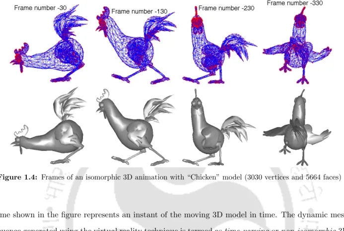
Instances of the 3D model present in successive frames are not isomorphic to each other. Mathematical representations of geometry and connection data for static 3D mesh and 3D animation are shown below.

Compression of 3D meshes
Some of the important transform methods that find use in 3D animation geometry compression are discrete cosine transform (DCT) [14], discrete wavelet transform (DWT) [15], principal component analysis (PCA) [7], singular value decomposition (SVD) [16] and spectral transform using Laplacian matrix plot [17] and so on. In this work, we have applied TFAN encoder for compression of 3D animation link data.
![Figure 1.9: Prediction with hierarchical B-frames for temporal scalability [1]](https://thumb-ap.123doks.com/thumbv2/azpdfnet/10551643.0/51.892.151.770.170.740/figure-1-prediction-hierarchical-b-frames-temporal-scalability.webp)
Distortion metrics for geometry compression algorithms
The spatial error corresponds to the sum of standard deviation of relative edge lengths calculated at each vertex within its topological neighborhood for all the frames. The temporal error is calculated as the sum of relative changes of virtual temporal edges between the two mesh series.
Motivation and problem formulation
Quality assessment of 3D animations involves subjective or objective evaluation of reconstructed 3D animation data relative to its original version based on object detectability. Subjective evaluation refers to the evaluation of the quality of reconstructed 3D animations by human observers in terms of opinion scores based on perceptual quality.
Thesis contributions
The geometric data of the individual 3D objects is then allocated for each IMO block. Geometric data of unique 3D objects are temporarily attached across frames to IMO blocks.
Organisation of the thesis
Introduction
Animation geometry compression using the PCA
PCA is applied to the animation geometry matrix A across frames to exploit spatial correlations. The PCA-LPC algorithm gives better geometry compression results for animation sequences that have a larger number of frames than the number of vertices per frame.
Animation geometry compression using the CPCA
The success of the above CPCA algorithm mainly depends on the efficiency of the clustering process. Based on the above observations, this chapter aims to carry out the following investigations for improving the performance of the CPCA algorithm with better clustering of vertex trajectories. i). The random initialization of the cluster centers in the CPCA algorithm is proposed to be replaced by a stable initialization method of cluster centers using the subtractive clustering (SC) technique [55].
Proposed subtractive clustering based CPCA method
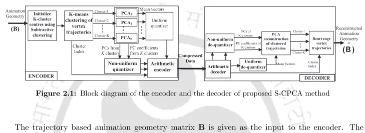
In this work, we proposed a block arithmetic coding for the quantization levels of PCs and PC coefficients of the trajectories of nodes in each cluster. For each cluster, combine the quantization levels of PCs that are quantized with the same qi as the block. The block diagram of the encoder and decoder for the proposed S-CPCA method is shown in Figure 2.1.
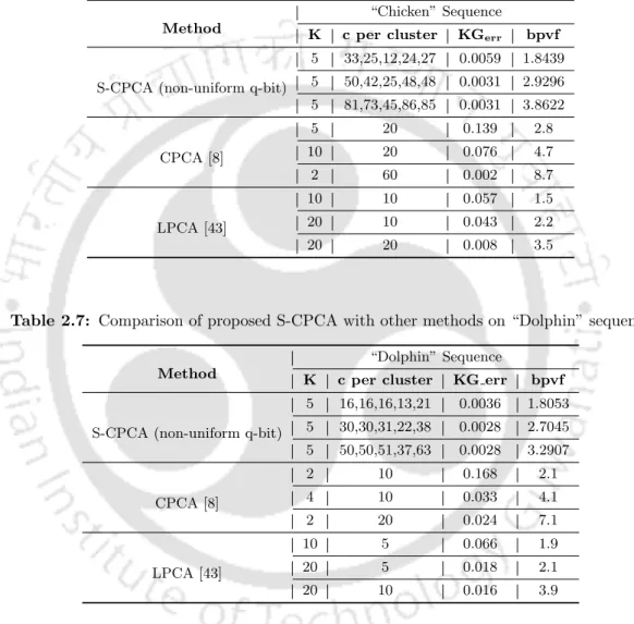
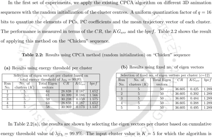
Experimental results
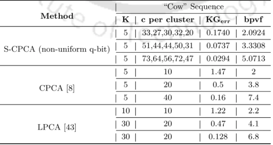
For comparison, we have also shown the results obtained using the CPCA method (average of 20 runs). The experimental results are evaluated with the results of S-CPCA method with uniform quantization. In this section, the performance of the proposed S-CPCA method is compared with the existing CPCA [8] and LPCA [43] methods.
Conclusions
633.4 Proposed spatiotemporally scalable animation geometry encoder using proposed spatiotemporally scalable animation geometry encoder using.
Introduction
Scalable compression of isomorphic 3D animations - a review
The predictive coding method exploits the spatial and temporal correlations present between the changing locations of vertices of 3D animations. The importance of each bit plane in the basis vectors is calculated according to its contribution to the quality of the grid sequence reconstruction. The elements of the base layer and the remaining prediction vectors of higher levels are encoded using bit plane encoding and sent to the decoder.
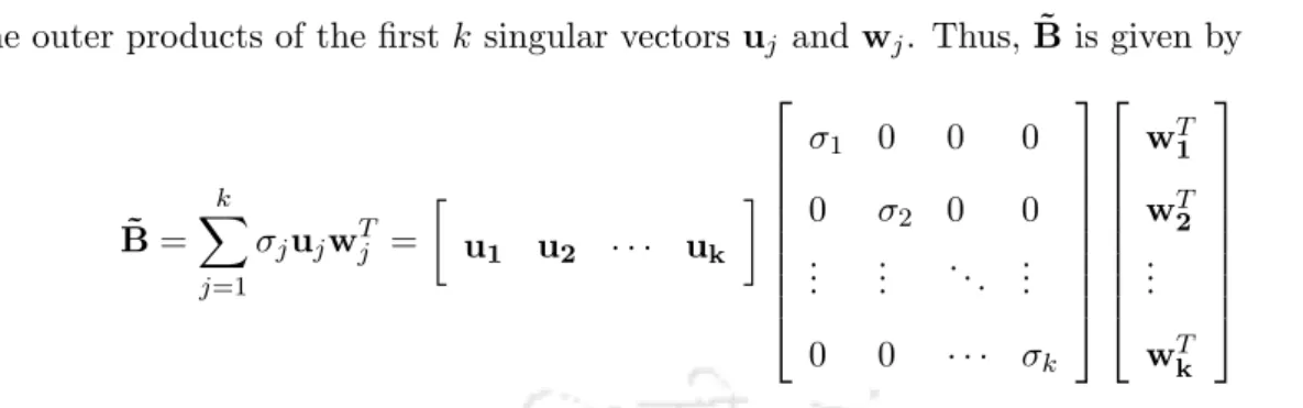
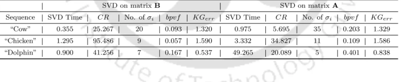
Proposed compression of trajectory-based geometry matrix us- ing SVD
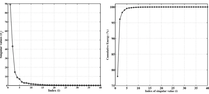
The R singular values are the square roots of the nonzero eigenvalues of BBT and BTB. It can be seen that most of the signal energy is captured by the first few singular values. 107 “Cow” sequence using different number of singular values and their corresponding spatial and temporal singular vectors.
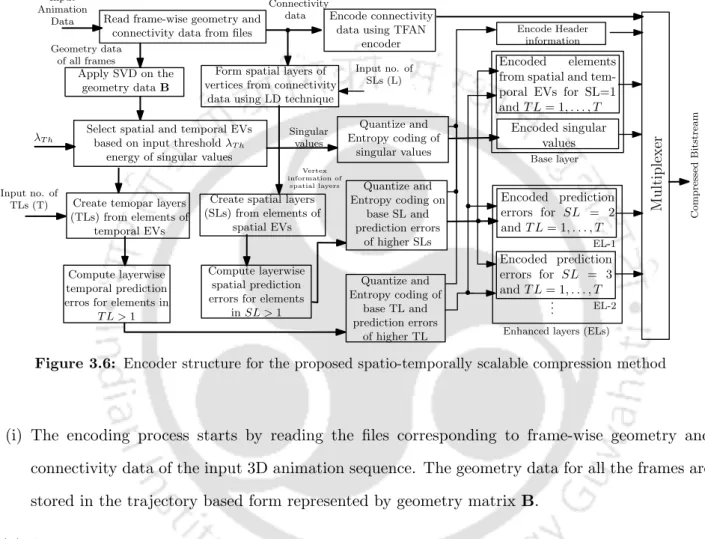
Proposed spatio-temporally scalable animation geometry coder using the SVD
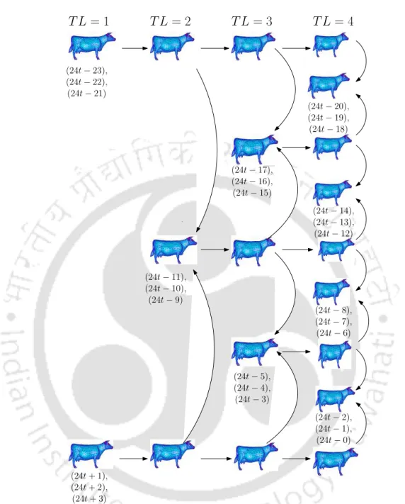
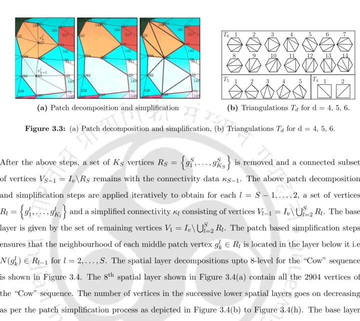
This grouping information is used to design the hierarchical spatial layers for geometric elements of the spatial singular vectors in the SVD domain. In the hierarchical decomposition of the temporal layer, the elements of the temporal single vectors are divided into different temporal groups. Design the hierarchical temporal layers using the elements of the temporal single vectors, as shown in Equation 3.23.
Experimental results
The prediction of the elements in the enhancement spatial layers is calculated as given in Equation (3.19). The other reason could be the rapid changes of the coordinates across the frames for the "Cow" sequence. The graph showing scalable compression performance of the "Dance" animation for different spatial layers (SL = 1 to 8) at a fixed temporal resolution (TL = 1) is shown in Figure 3.11(a).
Conclusions
Introduction
Classification of MO-3D animations
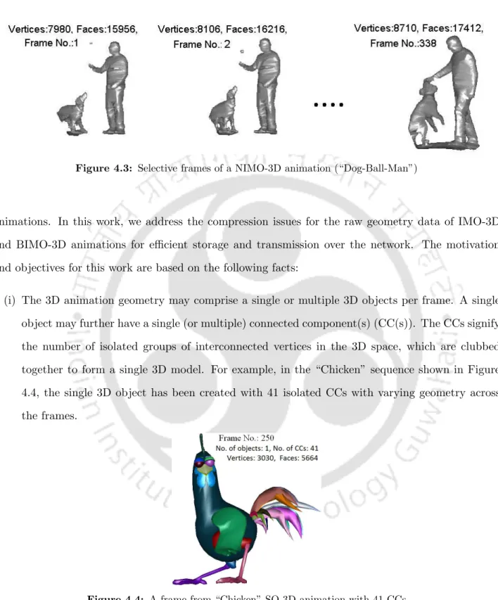
In block-isomorphic multi-object 3D animation (BIMO-3D), the topology information of the constituent 3D objects satisfies the graph isomorphism property for a set of consecutive frames treated as an IMO block or segment. In non-isomorphic 3D multi-object animation (NIMO-3D), the mesh attributes of 3D objects do not follow the framewise graph isomorphism property. In this case, the number of vertices and triangular faces of the composite multiple 3D objects changes in each frame along the length of the animation.
Motivation and the objectives
So, applying the geometry compression algorithms available for SO-3D animations to the overall 4D geometry data (3D+time) of multiple 3D objects requires a large amount of memory space and processing time. Such changes in the number of 3D objects and their mesh attributes occur in BIMO-3D animations as discussed above. Furthermore, existing geometry compression methods available for isomorphic 3D animations cannot be directly applied to BIMO-3D animations due to changes in the total number of 3D object vertices and their connection data per frame in the sequence.
Representation of the MO-3D animation geometry
Using the rough matrix representation of 3D animation geometry as given by Equation (1.6) in Chapter 1, the ABIM O animation geometry for BIMO-3D animation is written as . Similarly, using the trajectory-based matrix representation of 3D animation geometry as given by Equation (1.8) in Chapter 1, BIMO-3D animation geometry can also be represented by a set of matrices and written as . Connectivity data for BIMO-3D animation is represented by a set of connectivity matrices representing IMO blocks, written as
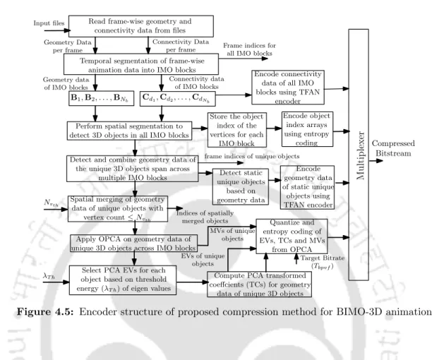
Proposed geometry compression method of BIMO-3D anima- tions
The geometry data of the detected 3D objects are extracted across the frames in an IMO block based on OIi. The spatial segmentation gives geometry and connectivity data of individual 3D objects for the frames in each IMO block. However, there may be geometry data from 3D objects present across multiple IMO blocks.
Experimental results
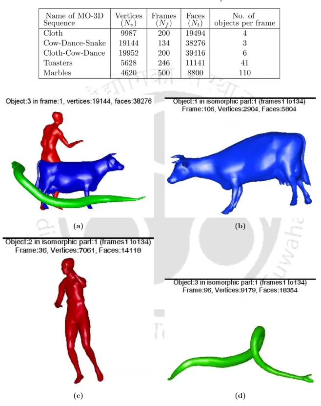
Four BIMO-3D animations are used to evaluate the compression performance of SA-PCA and G-PCA. The RD performance of SA-PCA is worse than the other two methods for all sequences. Cow-Dance-Snake” sequence with 3 objects in 3 IMO blocks, (c) “Cloth-Toasters” sequence with 45 objects in 3 IMO blocks, and (d) “Cloth-Cow-Dance” sequence with 6 objects in 3 IMO blocks .
Conclusions
Introduction
Distortion metrics for 3D meshes
A model-based approach calculates DM from geometric or other structural information of 3D models in 3D object space. On the other hand, the image-based approach computes DM values in image space using images of 3D models rendered from a viewpoint. However, not all model-based or image-based DMs applied to distorted meshes can provide results that correlate with subjective results.
Model-based DMs for 3D animations
The average Hausdorff distance (AHD) between Md and M˜d is calculated as the average of frame-symmetric HDs between the original and reconstructed grid sequences and recorded as an angle. The time part calculates the difference between the apparent time edges in the original and the distorted meshes for each frame point. The angle-based detection distance (APD) between Md and M˜d is based on the change in direction of movement by nodes across grid sequence frames.
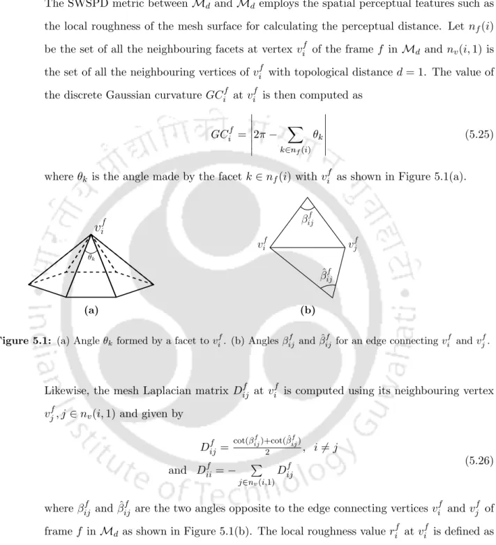
Proposed model-based PVD metric for 3D animations
In the proposed PVD metric, we have tried to incorporate the required properties of a PVD metric as follows. i) The proposed PVD metric is designed to demonstrate the invariance of the effect of the frame-based affine transformation operations, namely translation, scaling and rotation, applied to the original or the reconstructed animation. The mean and variance of the vertices of the frame f of the original and reconstructed mesh. The temporal edge lengthsel(et(i), f) and ˜el(et(i), f) for the vertex vfi inf-th frame of the original and the reconstructed animations are calculated as.
Experimental results
In this experiment, the correlation performance of the proposed AIST ED metric is evaluated on the UWB and the GIPSA-LAB 3D animation databases. Thus, we considered the DMOS values for both the WI and WOI sessions to calculate the SROCC(%) and PLCC(%) values of the proposed AIST ED metric using the GIPSA-LAB database. The distortion-wise SROCCs (%) of the objective DMs calculated with the DMOS values in the WOI and WI sessions are listed in Tables 5.10(a) and 5.10(b), respectively.
Conclusion
For the GIPSA-LAB 3D animation database, the proposed metric gives the best overall SROCC(%) and PLCC(%) values of 80.02 and 77.69, respectively, compared to the other metrics when considering the DMOS values for the WOI case. 3D animation geometry data corresponds to the changing dynamics of node positions relative to the frame representing 3D models over time. The research work in this thesis focused on the development of algorithms to compress this 3D animation geometric data.
Summary of contributions
A novel scalable compression method with an encoder and a decoder structure has been proposed to achieve spatio-temporal scalability using the singular value decomposition (SVD) of the 3D animation geometry data. The method deals with the compression of the geometry data of block-isomorphic multi-object 3D (BIMO-3D) animations. The proposed method applies a temporal segmentation algorithm to divide the animation data of the consecutive frames into several isomorphic multi-object (IMO) blocks.