PARAMETRIC OPTIMIZATION OF TURNING OPERATION ON STAINLESS STEEL USING A CARBIDE TOOL
A THESIS SUBMITTED IN PARTIAL FULFILLMENT OF THE REQUIREMENTS FOR THE DEGREE OF
Bachelor of Technology In
Mechanical Engineering
By
SUSHANTA SARMA Roll no-107ME016
Department of Mechanical Engineering National Institute of Technology
Rourkela 2011
PARAMETRIC OPTIMIZATION OF TURNING OPERATION ON STAINLESS STEEL USING A CARBIDE TOOL
A THESIS SUBMITTED IN PARTIAL FULFILLMENT OF THE REQUIREMENTS FOR THE DEGREE OF
Bachelor of Technology In
Mechanical Engineering
By
SUSHANTA SARMA
Under the Guidance of Prof K. P. MAITY
Department of Mechanical Engineering National Institute of Technology
Rourkela 2011
National Institute of Technology Rourkela
CERTIFICATE
This is to certify that this thesis entitled, “PARAMETRIC OPTIMIZATION OF TURNING OPERATION ON STAINLESS STEEL USING A CARBIDE TOOL” submitted by Mr.
SUSHANTA SARMA in partial fulfillments for the requirements for the award of Bachelor of Technology Degree in Mechanical Engineering at National Institute of Technology, Rourkela is an authentic work carried out by him under my guidance.
To the best of my knowledge, the matter embodied in the thesis has not been submitted to any other University / Institute for the award of any Degree or Diploma.
Date: Prof K. P. Maity
Professor
Department of Mechanical Engineering, National Institute of Technology, Rourkela- 769 008
ACKNOWLEDGEMENTS
I owe a great many thanks to a great many people who helped and supported me for the completion of this project effectively and moreover in time.
First, I express my deepest thanks to Prof. K.P. Maity, Department of Mechanical Engineering, National Institute of Technology Rourkela for giving me an opportunity to carry out this project under his supervision. He has been very kind and patient while suggesting me the outlines of this project and has clarified all my doubts whenever I approached him. I thank him for his overall support.
I am also thankful to Prof. Ranjit Kumar Sahoo, Professor and Head, Department of Mechanical Engineering, National Institute of Technology, Rourkela, for his constant support and encouragement.
I would also like to thank Mr. Kunal Nayek, Staff Member of the Production Engineering Laboratory and Sri Umesh Viswakarma, M. Tech Scholar of Production Engineering specialization for their assistance and help in carrying out experiments.
Last but not least, my sincere thanks to all the staff members of Central workshop who have patiently extended all sorts of help for accomplishing this undertaking.
Dt. SUSHANTA SARMA
Department of Mechanical Engineering National Institute of Technology Rourkela – 769008
i | P a g e
CONTENTS
Page No.
Abstract 1
1 introduction 2
2 Minimum chip thickness 4
3 Size effect 5
4 Ductile regime machining of brittle materials 5
5 Literature review 6
6 Design of experiment 12
7 Experimental set-up 15
7.1 Perimental conditions 16
7.2 Tool designation 16
7.3 Workpiece properties 17
8 Experimental data 18
9 Analysis of experimental data 18
10 Conclusion 24
11 Scope for further study 25
12 List of references 26
ii | P a g e
List of Figures
Sl no. List of figures Page No.
Fig 1 Experimental Set up 15
Fig a Attached W/P in chuck 15
Fig b Tool, dynamometer and W/P assembly 15
Fig 2 Main Effect Plots for Feed Force 20
Fig 3 Main Effect Plots for Thrust Force 22
Fig.4 Main Effect Plots for Cutting Force 23
iii | P a g e
List of Tables
Sl no. List of tables Page No.
Table 1 PERIMENTAL CONDITIONS 16
Table 2 Chemical composition 17
Table 3 Mechanical properties 17
Table 4 Experimental data(L9 orthogonal array) 18
Table 5 L9 array for feed force 19
Table 6 Anova table 19
Table 7 Response table for feed force: 20
Table 8 L9 array for thrust force 21
Table 9 Anova table for thrust force: 21
Table 10 Response table for thrust force 21
Table 11 L9 array for cutting force 22
Table 12 Anova table for cutting force: 23
Table 13 Response table for cutting force 23
1 | P a g e ABSTRACT:
The term microturning is used to refer to operation processes occurring at dimensions of 1 to 999 micrometres. Stainless steel is a widely used material in day to day applications. In this case, a carbide tool has been used to machine stainless steel. The machining parameters are cutting speed, feed and depth of cut. The main aim is to understand the optimum settings of these parameters to reduce the machining forces, namely the feed force, the thrust force and the cutting force. To better understand these effects, experiments were carried out on a lathe and the machining forces measured with a dynamometer. The mode of machining was chosen as wet machining. The Taguchi method and ANOVA were used to analyse the obtained results. The statistical software MINITAB was then used to confirm the results obtained from statistical analysis.
2 | P a g e 1. INTRODUCTION:
Progress in technology is inevitable. There is a continuous race on in the market to reduce costs and maximize profits through radical improvements in technology. One of the areas where there is a scope for improvement in technology is part production. Continuous efforts are being made to improve the technology involved so as to meet the demands of the society which are ever increasing. Newer manufacturing technology is being explored but more often than not, it has been found inefficient to carry out the needs. One of the attempts in improvement is towards minitiarisation. Another area where a lot of improvement is being done is in the improvement in the quality of the products. Precision and smoothness are desired in advanced part production processes.
The term micromachining is used to refer to operation processes occurring at dimensions of 1 to 999 micrometres. One such micromachining process is microturning. Microturning is similar to conventional turning operation but the workpiece and the part produced are much smaller in size. It becomes increasingly difficult to use conventional methods of manual machining to perform the operation as the size of the workpiece decreases and the features desired become more detailed. So computerized numerical control machines are used.
A few advantages of micro tooling machines like micro turning machines are as follows:
1. Micromachines aid in the conservation of energy. They help in saving a large amount of energy. In traditional machining, during the production of small parts, a lot of unnecessary energy consumption occurs. For example, a small part may be capable of being produced by the consumption of just 100 W of power. But if a conventional machine is used, it will consume the amount of power it has been designed to consume, say 10kW. So a micromachine consuming 100 W of power is 100 times
3 | P a g e more efficient than the convetional machine. The world today desires efficiency in the consumption of power with ever increasing demands for energy.
2. Conventional machining with large machines requires special peripheral equipment to aid in temperature control or vibration isolation. An important factor to ensure precision machining is to keep the temperature of the machine constant throughout the operation. In case of large conventional machines, the temperatures of large spaces, sometimes huge rooms, need to be controlled. Along with the associated complexity, there is unnecessary power consumption to ensure temperature control. But in case of micromachines, the temperature of a small chamber needs to be controlled. Another condition to ensure precision machining is vibration isolation. In case of large conventional machines, in order to isolate internal or external vibrations, the use of vibration free machine bed or even special building is necessitated. However, a micro machine does not need such systems. The natural frequency of micro machines is normally higher than that of vibrations caused by surroundings.
3. Micro machines can be easily installed and relocated within a shop floor. A micro machine does not require the construction of any special room or building or the presence of any high powered electric source. Thus the manufacturers can have a far more flexible layout and the factory layout can be easily changed to meet the changing demands of the market.
4 | P a g e 2. MINIMUM CHIP THICKNESS:
In microturning, there is a certain minimum chip thickness which greatly affects variables like cutting force, tool wear, surface integrity and this in turn affects the machining process performance. The concept of minimum chip thickness arises due to the edge radius effect. In microturning, the tool can be scaled down to a large extent but the sharpness of the tool cannot be scaled down proportionately. So, if the uncut chip thickness is less than the minimum chip thickness, no chip is generated. There are two mechanisms by which the minimum chip thickness effect affects the microturning process. They are chip removal and ploughing or rubbing. With the increased extent of ploughing or rubbing, cutting forces increase, burr formation occurs and surface roughness increases. So the analysis of the minimum chip thickness effect is very important.
However, the development of a theory for the estimation of the minimum chip thickness has run into a few problems. The experimental method to estimate the minimum chip thickness has been found to be quite tedious or expensive. Moreover, the accuracy of the observations is greatly affected by experimental uncertainties. Molecular dynamic simulation has been attempted but it is applicable only for nanometric scale machining. Some investigations have also resorted to microstructural finite element simulation but this approach involves a lot of computation and cannot be applied to a wide range of materials.
The thermomechanical properties of the material determine the normalized minimum chip thickness. Most of the properties are greatly affected by variations in temperature, strain and strain rate. The thermomechanical properties include yield strength and ductility. The variables like cutting temperature, strain and strain rate are in turn greatly affected by cutting conditions like cutting velocity and tool edge radius. Attempts are being made to ascertain the
5 | P a g e exact manner in which the normalized minimum chip thickness depends on the cutting conditions.
3. SIZE EFFECT:
For a small depth of cut, the „size effect‟ phenomenon appears. It consists of a non-linear increase in the specific cutting energy when the depth of cut decreases. The specific cutting energy is the ratio between the total cutting force acting on the tool in the cutting direction and the chip section.
The scaling effect would be caused by ploughing of machined material due to negative rake angle, strain rate dependency, dislocation density, pressure on the flank face due to elastic spring back and strain hardening of machined material at micrometrical scale.
4. DUCTILE REGIME MACHINING OF BRITTLE MATERIALS:
Ductile regime machining of brittle materials has some advantages. This is possible under controlled conditions. Low depth of cut and high pressure aids in ductile regime machining of brittle materials. The most important advantage of ductile regime machining over brittle regime machining is the minimum subsurface damage, the values of the surface roughness being of the order of a few nanometres. The brittle to ductile transition occurs when the hydrostatic pressure during machining approaches values close to the hardness of the material. When the cutting speed and depth of cut are low, the high pressure field causes the material to undergo transition to a metallic phase as a result of which the material exhibits a ductile behaviour. When the depth of cut and cutting speed are high, the temperatures involved are so high that the dominant mechanism for phase transformation is thermal softening.
6 | P a g e 5. LITERATURE REVIEW:
An efficient methodology must be developed to derive the normalized minimum chip thickness. To do so, Liu et al.[1] has made use of the basic thermomechanical properties and the molecular mechanical theory of friction. The main aim is to extend the knowledge of minimum chip thickness values to as many materials as possible when these materials are put to wide range of cutting conditions. The important properties which have been formulated are shear strain and strain rate along with cutting temperature. The cutting temperatures at both the work-chip interface and the chip-tool interface have been considered. To aid in the formulations, a slip-line field model has been used. This model accounts for the finite tool edge radius. To determine the condition for transition from ploughing to microcutting, the Kragelskii- Drujanov equation is used. To estimate the effective flow stress under high strain rate, high temperature and high strain, the Johnson- Cook model (for aluminium alloy) and the Oxley model (for carbon steels) have been combined. For experimental design, the materials used are 1040 steel and Al 6082-T6. There are two contrasting ways in which increased cutting velocity affects minimum chip thickness. Firstly, the cutting temperatures increase with increased cutting speed leading to an increase in thermal softening effect and consequent increase in ductility. So, the minimum chip thickness increases too. Secondly, with increase in cutting velocity, effective strain and strain rate increase which increases the strain hardening effect. So, the minimum chip thickness and ductility decrease. It was seen that for machining carbon steels, minimum chip thickness increases as cutting velocity and tool edge radius increase. Again, higher the carbon content of the steels, larger the minimum chip thickness is. While machining aluminium, it was seen that the minimum chip thickness values remain constant over a wide range of cutting speeds and tool edge radii. So, for machining carbon steels, high velocities are not used while for machining aluminium alloys, high velocities are used for increased productivity.
7 | P a g e H.S.Yoon et al. [8] has proposed an orthogonal cutting force model based on slip-line field model for micro machining. Two material flow processes are being considered- chip formation process and ploughing. The paper takes into account the effects of parameters like effective rake angle, depth of deformation and minimum chip thickness. The edge radius effect is an important effect in machining processes. The tool can be scaled down to a large extent but the sharpness of the tool cannot be scaled down so drastically and proportionately.
So, in micro machining ploughing force is a important factor instead of shearing force which is the dominant factor in conventional machining. Another important effect is the minimum chip thickness effect. When the undeformed chip thickness is below the minimum chip thickness, chip formation doesn‟t occur and there is only ploughing. However, when the undeformed chip thickness exceeds the minimum value, chip formation occurs. Some experimental analysis has shown that chip formation occurs only when the undeformed chip thickness is more than 30% of the tool edge radius. This paper is based on the assumption that the tool has a perfectly rounded tool edge. The cutting performed is assumed to be orthogonal. The material deforms plastically below the minimum chip thickness height.
Another assumption is that the work material is not work-hardening. So, the shear stresses on all shear planes have the same values. The chip is also assumed to be a free body, such that the normal force on the shear plane is zero. The paper has also concentrated on the effect of the dead metal zones on micro machining. These zones act as stable built up edges on the tool, as stagnation zones where no material flow occurs.
Eugen Axinite [2] has studied the surface roughness on micro turning of titanium alloys (Ti6Al4V). Conventional turning on these titanium alloys is difficult. Firstly, the tool life is short and then long chips are formed which cause the problem of removal from the machine.
So, micro turning of these alloys has gained in importance. When a tool with a nose radius is used, ridges having geometries corresponding to the geometry of the tool nose get left behind
8 | P a g e on the finished surface. Also, very high normal stresses get developed in the metal at the trailing edge. This metal flows to the side relieving the stress and in the process, creating a furrow increasing the roughness. Particularly, soft ductile materials show this problem.it is observed that in case of microturning the surface roughness first decreases with feed, reaches a minimum and then increases if the feed is further increased. The final model for prediction of surface roughness consists of roughness of cutting edge, roughness associated with plastic side flow and kinematics‟ surface roughness.
Z J Zhou et al. [10] has taken up the case of ultraprecision machining to study the effect of diamond tool sharpness on cutting surface integrity and minimum chip thickness. Good surface integrity is an essential requirement of machining processes. Good surface integrity implies smaller surface roughness and smaller residual stresses combined with high dimensional accuracy. However, the accuracy of the relative motion between the cutting edge and the workpiece governs the achievable machining accuracy. So, the performance of machine tools needs to be studied. The workpiece material used is aluminium alloy. It was found that sharper the cutting edge, smaller the surface roughness. So, a sharp tool is preferable. To study the effect on the hardening of the machined surface layer, a micro Vickers was used to measure the micro hardness. It was observed that the surface machined with a sharp tool has lesser hardness compared to a surface machined with a dull tool. Also, a tool with a large cutting edge radius corresponds to bigger residual stresses for a given depth of cut. In a certain range of depth of cut values, it was seen that the residual stresses reduce with decrease in depth of cut. As the depth of cut reaches a critical value, the residual stresses increase as cutting depth decreases. The effect of depth of cut on the residual stresses can be explained with the help of the size effect. When the depth of cut reaches values comparable to that of the cutting edge radius, there is severe rubbing or burnishing action. As a result, the
9 | P a g e specific machining energy increases and the material near the tool tip get plastically deformed to a large extent. Sharper tools give smaller cutting thickness.
N. Fang et al. [4] has attempted a modeling of built up edge formation in machining. The size of the built up edge can be quantitatively predicted and the effect of built up edge on chip flow and cutting forces can be studied under different machining conditions. The built up edge in machining is an irregular and unstable structure formed on the tool rake surface during machining of ductile materials ad alloys like steels and aluminium alloys. It comprises of several successive layers hardened under extreme strain conditions at the chip-tool interface. This model is very important since it predicts built up edge formation in machining.
It also predicts the chip uncurling effect that plays an important role in machining. It establishes the relationship between the size and boundary of the built up edge and machining parameters like chip thickness, chip tool contact length, chip up-curl radius and cutting and thrust forces.
Kim et al. [9] has suggested an orthogonal cutting model called the round edge cutting model.
This model has concentrated on two factors, firstly the elastic recovery of the workpiece causing sliding along the clearance face and secondly on ploughing. The results of this model have been compared with those of Merchant‟s model. One of the assumptions is that cutting is a two-dimensional plastic process. The normal stress is assumed to be constant while the shear stress changes in the region where the tool is rounded. The workpiece is elastically recovered in the clearance face. It has been observed that for depths of cut less than 1 micron, the round edge cutting model of Kim better approximates the cutting forces compared to the sharp edge cutting model of Merchant. At such low depths of cut, the friction along the flank face and the effective negative rake angle are factors that need to be considered.
10 | P a g e Ajjarapu et al. [7] has made a study of the ductile regime machining of silicon nitride. Depths of cut ranging from 250nm to 10μm are chosen for machinability tests. The Drucker-Prager yield criterion is implemented in the software AdvantEdge to study the mechanical behaviour of silicon nitride. Depths of cut ranging from 1 μm to 40 μm and rake angles ranging from 0°
to -60° are used for numerical simulations. It was observed that higher negative rake angles result in development of higher pressures in the workpiece. Similarly experiments have shown that the regime for machining is ductile when the values of depth of cut chosen are less than 1 micron.
Jiwang Yan et al. [6] has attempted to discuss ductile regime turning at large tool feeds. A very important problem in using ductile regime turning is tool wear. The existing method of using a round nosed diamond tool introduces limitations on feed. In this paper, the authors have proposed the use of a straight nosed diamond tool. A small tool feed results in a long cutting distance. If other conditions are kept constant, tool wear volume increases with cutting distance. So, a smaller tool feed leads to a greater tool wear. A small tool feed also results in increased machining time and low machining efficiency. If a straight edged diamond tool is used, undeformed chip thickness becomes uniform along the main cutting edge. So, a uniform cutting mode may be expected. In the diamond turning process, brittle machining involves tensile cleavage fracture while ductile machining involves large-strain plastic deformation. This model adopts small cutting edge angles and thus allows thinning of chip thickness in the range of nanometres. This model enables plain strain conditions too.
Ductile regime turning could be done at large tool feeds up to some tens of micrometers.
T.P.Leung et al. [5] has attempted to study the ductile regime diamond turning of silicon substrates. Machining silicon in the brittle regime is not suitable because of its low fracture toughness. The effect of variation in parameters such as depth of cut, feed rate and tool rake angles on ductile regime turning of silicon using a diamond tool needs to be investigated.
11 | P a g e Three distinct regimes could be observed in the machining process, the elastic regime, the ductile regime and the brittle regime. In the ductile regime, the surface is smooth and it was observed that there were no cracks or pits. The brittle regime has intensive surface cracks.
The orientation of the crystal is another factor that affects the critical depth of cut. The size of the cracks increases with increase in the depth of cut. To obtain an optical surface on silicon substrate in diamond turning, the chip thickness must not exceed a critical value. The surface finish was found to become very good as the feed rate or the depth of cut was put below certain values. With an increasing negative rake angle, the surface roughness was found to improve.
Blackley et al. [3] has suggested an entirely different model for ductile regime diamond turning of brittle materials. Two parameters, the critical depth of cut and the subsurface layer damage are used to characterise the material removal process. A process limit called the maximum feed rate has been introduced to understand the process better. The effect of the rake angle, tool nose radius and machining environment on the machinability has been studied. The material used for experimental study is germanium and the lubricant used for machining is distilled water. Better machining is observed at highly negative rake angles.
However as the rake angles are made more and more negative, the surface finish decreases in quality. It was observed that ductile regime machining for germanium is better in the dry state than in the wet state using distilled water as the lubricant. With an increase in the tool nose radius, the machinability of the material is found to improve. Though an exact explanation of the observed phenomena has not been attempted, it can be speculated that the magnitude and direction of the cutting forces play an important role in the displayed characteristics.
12 | P a g e 6. DESIGN OF EXPERIMENT:
A designed experiment is a series or a series of tests in which some purposeful changes are made to the input variables of a process and then the corresponding changes in the output response are identified and observed.
The process variables may be controllable or uncontrollable of which the
uncontrollable factors are called noise factors.
The objectives of experimental design may include:
1) Determining the most influential variables on the response, y.
2) Determining where to set the influential x‟s such that y is near the nominal requirement.
3) Determining where to set the influential x‟s such that variability in y is small.
4) Determining where to set the influential x‟s such that the effects of the uncontrollable variables z are minimized.
Statistical process control and design of experiment, though two closely related tools for improvement and optimization of processes, design of experiment offers a more effective method as compared to statistical process control. Statistical process control is a passive statistical method; we watch the process and then wait for some information that leads to a useful change. Passive information may not provide much useful information if the process is in control. However, design of experiments is an active statistical method: a series of tests are actually being performed on the process, making changes in the input, and observing the corresponding changes in the outputs. This leads to information that can lead to process improvement.
13 | P a g e Guidelines for designing experiments:
1) Recognition of and statement of the problem: It is highly essential to fully develop all ideas about the problem at hand and also about the specific objectives of the experiment. Input from all concerned parties- engineering, marketing, customers, quality, management and the operators are to be solicited. This helps in better process understanding and eventually solving the problem.
2) Choice of factors and levels: Choices of factors to be varied in the experiment must be made, the ranges over which the factors are varied and the specific levels at which runs are made. Process knowledge is a combination of practical knowledge and theoretical understanding and it is necessary for proper choice.
The number of factor levels should be kept low for factor screening. All factors that may be of importance must be examined. Much stress should not be laid on post experience.
3) Selection of the response variable: While selecting the response variable, it must be ascertained that the variable actually provides useful information about the process under study. Very often, the mean or standard deviation or both are chosen as response variables.
4) Choice of experimental design: Choice of design requires consideration of sample size, selection of a suitable run order for experimental trials and whether or not blocking and other randomization restrictions are involved.
5) Performing the experiment: While running the experiment, it is necessary to carefully monitor the process to ensure that everything is being done according to the plan. Errors in experimental procedure at this stage generally destroy experimental validity.
14 | P a g e 6) Data analysis: Statistical methods should be used to analyse the data such that
results and conclusions are objective and not judgemental. Use of simple graphical methods as well as software is done.
7) Conclusions and recommendations: Once the data has been analysed, the experiment should draw practical conclusions about the results and hence recommend a course of action.
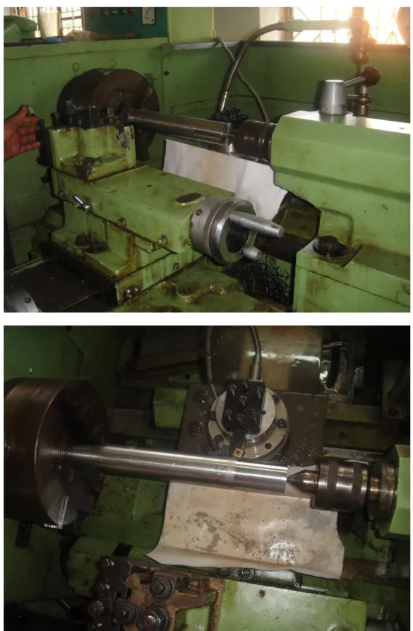
15 | P a g e 7. EXPERIMENTAL SET-UP:
The experiment was performed on the HMT NH26 lathe and the machining forces were measured with the help of a KISTLER 9272 dynamometer.(Fig 1)
Fig a (attached W/P in chuck) Fig. b (tool, dynamometer and W/P assembly) Fig a
Fig b
16 | P a g e 7.1.EXPERIMENTAL CONDITIONS(Table 1)
Workpiece material AISI 304 steel
Inserts used Uncoated cemented carbide insert (ISO
P30 grade)
Insert designation SCMT 12 04 08
Tool geometry −6°, −6°, 6°, 6°, 15°, 75°, 0.8 (mm)
Cutting velocity (m/min) 38.5,66,112.3
Feed(mm/rev) 0.04,0.06,0.08
Depth of cut(mm) 0.4,0.6,0.8
Environment Wet
7.2.TOOL DESIGNATION:
SCMT 12 04 08
12 implies length of each cutting edge is 12 mm 04 implies nominal thickness of the insert is 4 mm 08 implies nose radius is 0.8 mm
17 | P a g e 7.3.WORKPIECE PROPERTIES:
AISI 304 steel
It is an austenitic standard chromium nickel steel.
Chemical composition: Table 2
Element Weight %
C 0.08
Mn 2.00
Si 1.00
Cr 18-20
Ni 8.0-10.5
P 0.045
S 0.03
Mechanical properties: Table 3
Density (×1000 kg/m3) 8
Poisson's Ratio 0.27-0.30
Elastic Modulus (GPa) 193
Tensile Strength (Mpa) 515
Yield Strength(MPa) 205
Elongation (%) 40
Hardness (HRB) 88
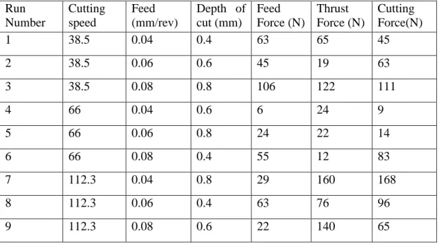
18 | P a g e 8. EXPERIMENTAL DATA
:
Table 4: L9 orthogonal array Run
Number
Cutting speed (m/min)
Feed (mm/rev)
Depth of cut (mm)
Feed Force (N)
Thrust Force (N)
Cutting Force(N)
1 38.5 0.04 0.4 63 65 45
2 38.5 0.06 0.6 45 19 63
3 38.5 0.08 0.8 106 122 111
4 66 0.04 0.6 6 24 9
5 66 0.06 0.8 24 22 14
6 66 0.08 0.4 55 12 83
7 112.3 0.04 0.8 29 160 168
8 112.3 0.06 0.4 63 76 96
9 112.3 0.08 0.6 22 140 65
9. ANALYSIS OF EXPERIMENTAL DATA:
9.1. TAGUCHI METHOD:
This quality design technique was first proposed by Taguchi in the 1960s. It greatly aids in improving industrial product quality. In the preliminary study, feed force was set as the objective function of the microturning experiment. Three factors, cutting speed, feed and depth of cut are taken as the machining parameters. The objective function is subject to the rule „smaller the better‟. So, the table for Taguchi analysis will be as follows:
19 | P a g e Table 5: L9 array for feed force:
L9 A B C Yi MSD S/N
1 38.5 0.04 0.4 63 3969 -35.987
2 38.5 0.06 0.6 45 2025 -33.06
3 38.5 0.08 0.8 106 11236 -40.506
4 66 0.04 0.6 6 36 -15.563
5 66 0.06 0.8 24 576 -27.604
6 66 0.08 0.4 55 3025 -34.807
7 112.3 0.04 0.8 29 841 -29.248
8 112.3 0.06 0.4 63 3969 -35.987
9 112.3 0.08 0.6 22 484 -26.848
A: Cutting Speed B: Feed C: Depth of cut
Table 6: ANOVA TABLE
Factor Sum of square DOF Sum of mean
square
Contribution
A 166.873 2 83.437 0.389
B 82.023 2 41.011 0.191
C 171.960 2 85.980 0.400
Total 428.954 6 214.477 1
20 | P a g e Table 7: RESPONSE TABLE FOR FEED FORCE:
A B C
1 -36.52 -26.93 -35.59
2 -25.99 -32.22 -25.16
3 -30.69 -34.05 -32.45
Delta 10.53 7.12 10.44
Mean of SN ratios
112.3 66.0
38.5 -25.0
-27.5 -30.0 -32.5 -35.0
0.08 0.06
0.04
0.8 0.6
0.4 -25.0
-27.5 -30.0 -32.5 -35.0
S F
DOF
Main Effects Plot for Feed
Signal-to-noise: Smaller is better
Fig 2(Main Effect Plots for Feed Force)
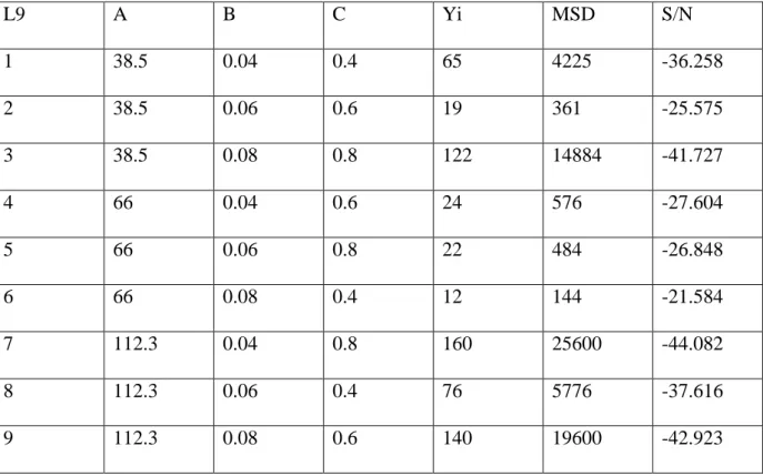
21 | P a g e Table 8: L9 array for thrust force:
L9 A B C Yi MSD S/N
1 38.5 0.04 0.4 65 4225 -36.258
2 38.5 0.06 0.6 19 361 -25.575
3 38.5 0.08 0.8 122 14884 -41.727
4 66 0.04 0.6 24 576 -27.604
5 66 0.06 0.8 22 484 -26.848
6 66 0.08 0.4 12 144 -21.584
7 112.3 0.04 0.8 160 25600 -44.082
8 112.3 0.06 0.4 76 5776 -37.616
9 112.3 0.08 0.6 140 19600 -42.923
A: Cutting Speed B: Feed C: Depth of cut Table 9: ANOVA TABLE FOR THRUST FORCE:
Factor Sum of square DOF Mean sum of
square
Contribution
A 395.74 2 197.87 0.755
B 65.08 2 32.54 0.124
C 63.37 2 31.69 0.121
Total 524.2 6 262.10 1
Table 10 : RESPONSE TABLE FOR THRUST FORCE:
A B C
1 -34.52 -35.98 -31.82
2 -25.35 -30.01 -32.03
3 -41.54 -35.41 -37.55
Delta 16.19 5.97 5.73
22 | P a g e
Mean of SN ratios
112.3 66.0
38.5 -25
-30 -35 -40
0.08 0.06
0.04
0.8 0.6
0.4 -25
-30 -35 -40
S F
DOF
Main Effects Plot for Thrust
Signal-to-noise: Smaller is better
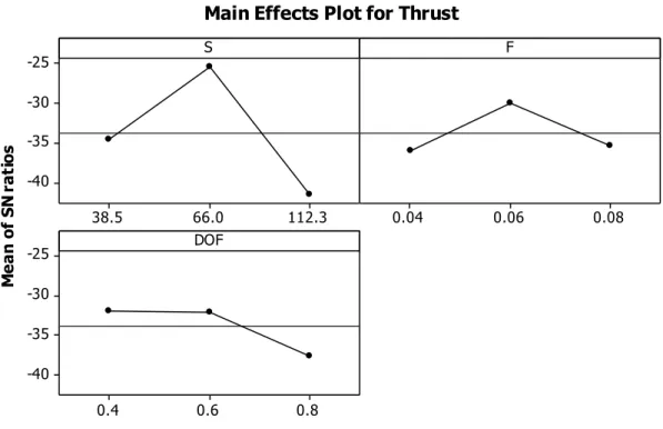
Fig 3(Main Effect Plots for Thrust Force)
Table 11: L9 array for cutting force:
L9 A B C Yi MSD S/N
1 38.5 0.04 0.4 45 2025 -33.064
2 38.5 0.06 0.6 63 3969 -35.987
3 38.5 0.08 0.8 111 12321 -40.906
4 66 0.04 0.6 9 81 -19.085
5 66 0.06 0.8 14 196 -22.923
6 66 0.08 0.4 83 6889 -38.382
7 112.3 0.04 0.8 168 28224 -44.506
8 112.3 0.06 0.4 96 9216 -39.645
9 112.3 0.08 0.6 65 4225 -36.258
A: Cutting Speed B: Feed C: Depth of cut
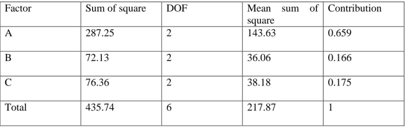
23 | P a g e Table 12ANOVA TABLE FOR CUTTING FORCE:
Factor Sum of square DOF Mean sum of
square
Contribution
A 287.25 2 143.63 0.659
B 72.13 2 36.06 0.166
C 76.36 2 38.18 0.175
Total 435.74 6 217.87 1
Table 13. RESPONSE TABLE FOR CUTTING FORCE:
A B C
1 -36.65 -32.22 -37.03
2 -26.80 -32.85 -30.44
3 -40.14 -38.52 -36.11
Delta 13.34 6.30 6.59
Mean of SN ratios
112.3 66.0
38.5 -25
-30 -35
-40
0.08 0.06
0.04
0.8 0.6
0.4 -25
-30 -35 -40
S F
DOF
Main Effects Plot for Cutting
Signal-to-noise: Smaller is better
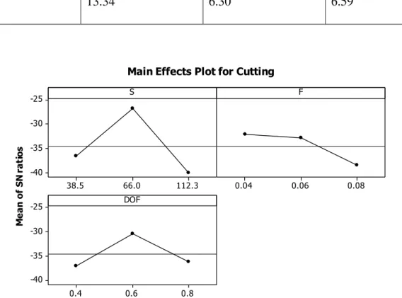
Fig 4 (Main Effect Plots for CuttingForce)
24 | P a g e 10. CONCLUSION:
While studying the effect of the cutting parameters on the feed force, it was observed that both the cutting speed and the depth of cut play equally important roles in the effect on the feed force. The role of the feed given is not crucial to the same extent. The optimum condition for machining to reduce feed force would be A2 B1 C2 ie.the speed kept at 66 m/min, the feed kept at 0.04 mm/rev and the depth of cut kept at 0.6mm.
While studying the effect of the cutting parameters on the thrust force, it was observed that the cutting speed exerts a huge influence on the magnitude of the thrust force while the effect of feed and depth of cut on thrust force is comparatively less and equal to each other approximately. The optimum condition of machining to reduce thrust force is given by A2 B2 C1 ie.the speed kept at 66m/min, the feed kept at 0.06 mm/rev and the depth of cut kept at 0.4mm.
While studying the effect of the cutting parameters on the cutting force, it was observed that the effect of the cutting speed far outweighs the effect of the feed and the depth of cut, which are again roughly equal. The optimum condition for machining to reduce cutting force would be A2 B1 C2 ie.the cutting speed kept at 66 m/min, the feed kept at 0.04mm/rev and the depth of cut kept at 0.6 mm.
The above mentioned conclusions suggest that a good combination of the input parameters for decreasing feed force, thrust force and cutting force is A2 B1 C2, cutting speed 66m/min, feed 0.04mm/rev and depth of cut 0.06mm.
25 | P a g e 11. SCOPE FOR FURTHER STUDY:
It was planned originally that the effect of the cutting variables (feed, speed and depth of cut) on machining forces in machining through coated carbide tools too would be studied. This could not be accomplished due to the lathe machine not being in operating condition. This can be done in the future and a comparative analysis may be made between coated and uncoated tools to find out the effect of coating on the machining forces.
26 | P a g e LIST OF REFERENCES:
1. Liu X., DeVor R.E. and Kapoor S.G., “An Analytical Model for the Prediction of Minimum Chip Thickness in Micromachining”, Journal of Manufacturing Science and Engineering, MAY 2006, Vol. 128, pp. 474-481
2. Axinte Eugen, ABOUT THE SURFACE ROUGHNESS ON MICROTURNING OF TITANIUM ALLOYS, Universitatea Tehnică “Gh. Asachi”, Iaşi Tomul LIII (LVII), Supliment, 2007 Secţia CONSTRUCŢII DE MAŞINI
3. W. S. Blackley and R. O. Scattergood, Ductile-regime machining model for diamond turning of brittle materials, PRECISION ENGINEERING-103
4. N. Fang, P. Dewhurst, Slip-line modeling of built-up edge formation in machining, International Journal of Mechanical Sciences 47 (2005) 1079–1098
5. T.P. Leung, W.B. Lee, X.M. Lu, Diamond turning of silicon substrates in ductile- regime, Journal of Materials Processing Technology 73 (1998) 42–48
6. Jiwang Yana,Katsuo Syoji, Tsunemoto Kuriyagawa, Hirofumi Suzuki, Ductile regime turning at large tool feed, Journal of Materials Processing Technology 121 (2002) 363–372
7. Satya K. Ajjarapu, Ronnie R. Fesperman, John A. Patten and Harish P. Cherukuri, Ductile Regime Machining of Silicon Nitride: Experimental and Numerical Analyses, Center for Precision Metrology, Department of Mechanical Engineering and Engineering Science The University of North Carolina at Charlotte Charlotte, NC 28223-0001, USA
8. H.S. Yoon, K.F. Ehmann, A Slip-line field model for orthogonal micro-machining processes, Department of Mechanical Engineering, Northwestern University, IL, U.S.A.
27 | P a g e 9. Jeong-Du Kim, Dong Sik Kim, Theoretical analysis of micro-cutting characteristics in
ultra-precision machining, Journal of Materials Processing Technology 49 (1995) 387- 398
10. Z.J. Yuan , M. Zhou, S. Dong, Effect of diamond tool sharpness on minimum cutting thickness and cutting surface integrity in ultraprecision machining, Journal of Materials Processing Technology 62 (1996) 327-330