146 Figure 4.7 Influence of AMB residual misalignment on the rotor system's orbital response (a) Rotor displacement at AMB 1 (b) Control current at AMB 1 (c) Rotor displacement at AMB 2 (d) Control current at AMB 2. 150 Figure 4.8 System responses in the time domain (a, b) x-displacement and current at AMB 1 (c, d) x-displacement and current at AMB 2 for residual misalignment case (e, f) x-displacement and current at AMB 1 (g, h) x- displacement and stream at AMB 2 for additional trial variance case.
Significance of the Study
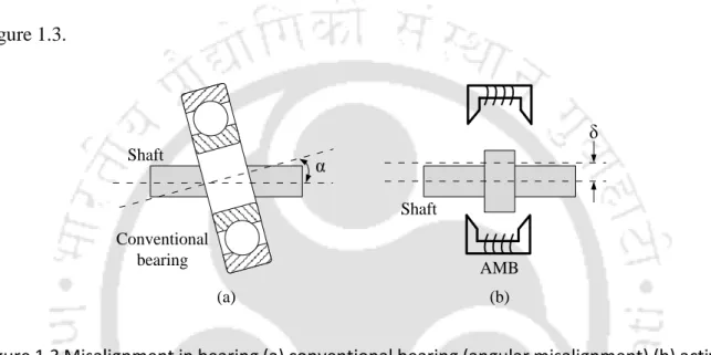
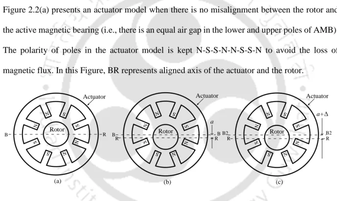
However, it is difficult to accurately locate the center position of the AMB in both the vertical and horizontal directions through. This inability to find the exact location of the AMB center will lead to residual misalignment of the axes of the AMBs relative to the absolute reference of the rotor operating axis.
Review on Condition Monitoring of Rotating Machinery
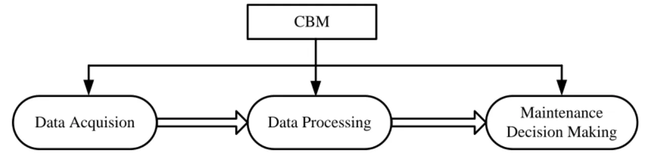
Quantifying the severity of the damage must be done at the next level. Finally, the remaining service life of the monitored structure can be predicted in the forecasting process.
Literature Review on Faults in Rotating Machinery
- Unbalance in Rotor
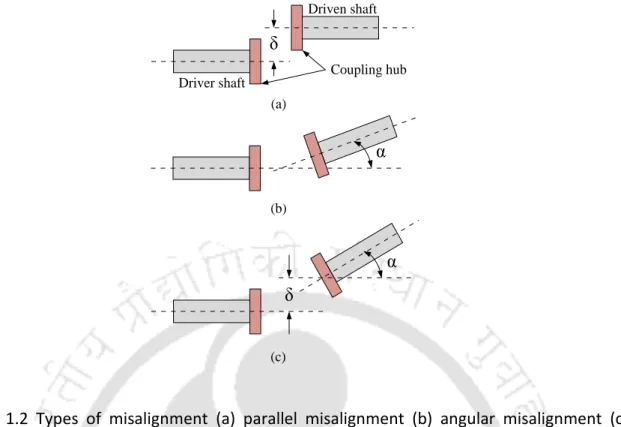
- Rotor Misalignment
- Multiple Faults in Rotating Machinery
They also calculated the misalignment forces and moments from forced reactions of the rotor system. Corresponding load minimization method (one of the model-based techniques) was used for the identification of the location and severity of faults.
Review on Condensation Schemes
The degrees of freedom eliminated during the reduction process are called slave DOFs, and the degrees of freedom retained for analysis are called master DOFs. They extended the hybrid reduction method for damping in the rotor system (Karthikeyan and Tiwari presented a repeated improved reduced system method (IIRS) combined with a substructure scheme for both undamped and damped structures. Moreover, the researchers still depend on the dynamic condensation method for eliminating the rotating DOFs in the analytical model.
Review on AMB and its Applications in Rotor System
Further, a fault identification algorithm was developed by Tsai et al. 2009) to analyze disturbances in actuators together with sensors in a rotor system integrated with AMB. AMB was used as an excitant by Xu et al. 2016) to detect outer ring failure in rolling bearings. Later, they used multiple AMBs (two thrust and two radial AMBs at the front and rear positions) to support the rotor and identified the stiffness and damping coefficients of the AMBs using the experimentally measured unbalanced response (Xu et al., 2017).
Outcomes of the Literature Review
It is clear from the above literature that an enormous amount of work has been carried out in the field of presenting an overview of working principles, hardware components and applications of AMB in turbomachines and gas turbines. In recent days, researchers are also focusing on using AMB technology for multiple fault identification and active balancing of rotor in a rotating machinery. Finally, the research papers published on condensation schemes and applications of AMB in the field of rotor dynamics are presented in a concise manner.
Objectives of the Present Work
Organisation of the Thesis
Finally, Chapter 5 is an extension of Chapter 4, in which distortion is also considered in non-contact displacement sensors together with faulty AMBs. The identification algorithm derived from the VTM strategy has been developed and used in the estimation of the unbalance parameters, residual misfits of AMBs and their stiffness constants. The VTM approach was used in identifying the offset quantities of the sensors located at the AMB locations.
Introduction
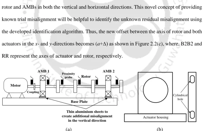
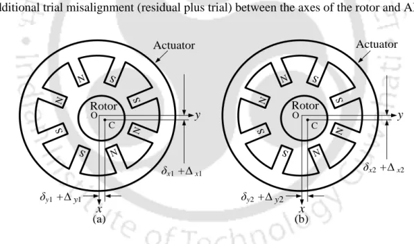
Two cases of misalignment depending on the amount of radial offset between the rigid rotor and AMB axes have been investigated for the study. In the second case (ie, additional trial misalignment), a trial offset is added in addition to the remaining misalignment. The linearized form of force due to misaligned AMB is also innovatively derived for residual and additional misalignment cases in the experiment.
System Configuration and Basic Assumptions
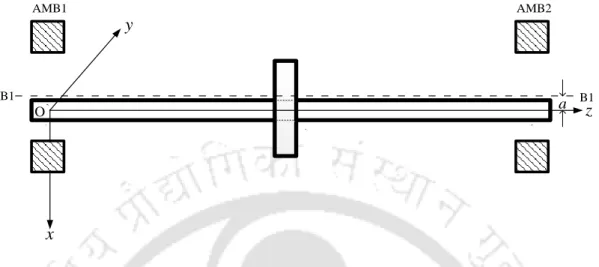
These responses have been used in the identification algorithm to estimate the unbalance and stiffnesses of misaligned AMBs as well as the amount of misalignment between the rotor and AMBs. It is assumed that the misalignment between the rotor and the AMB axes in the x and y directions is the same. Both AMBs are also assumed to be identical with the same force-displacement and force-current stiffness.
Mathematical Modelling and Equations of Motion of the Rotor-AMB System
- Unbalance Force Model
- Force due to Active Magnetic Bearing on the System
- AMB Force Model for Residual Misalignment
- AMB Force Model for Additional Trial Misalignment
- Equations of Motion of the Unbalanced and Misaligned Rotor-AMB Model
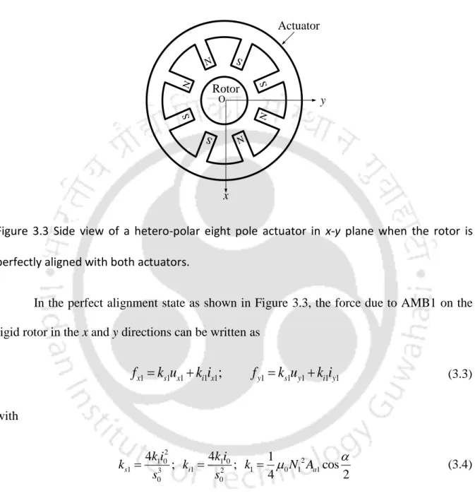
In the perfectly aligned case (Schweitzer and Maslen, 2009), the force acting on the rotor due to AMB in x direction can be expressed as. Based on this consideration, the force on the rotor due to a misaligned AMB in the x direction can be expressed as. Similarly, the force on the rotor due to a misaligned AMB in the y direction can be written as.
Development of Unbalance and AMB Misalignment Identification Algorithm
- Fast Fourier Transform based Response Generation
- Procedure for Estimation of Unbalance and Misalignment Parameters
From regression equations (i.e. equations (2.30) and (2.31)) it can be seen that the number of equations (i.e. four) is less than the number of unknowns (i.e. five), so it is a class of underdetermined systems of equations. Therefore, equations (2.30) and (2.31) can be combined to obtain the unique values of these unbalance parameters. Choose a specific rotational speed, ωn or a range of speeds. Generate the time-domain solutions of equations (2.17) and (2.18) for residual and additional trial misalignments.
Numerical Response Generation and Identification
- Quantitative Estimation of Unbalance and AMB Misalignment Parameters
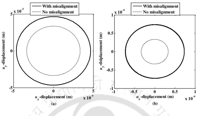
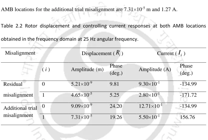
In accordance with Equation (2.17) for residual misalignment, the rotor displacement and current responses of the system in x and y directions at a corner frequency of 25 Hz are depicted in Figure 2.7. FFT plots of the rotor displacement and control current signals at AMB locations with their amplitude and phase at a corner frequency of 25 Hz for residual misalignment are presented in Figure 2.8. It is noteworthy from Table 2.2 that the peak values of the rotor displacement and current responses for the residual misalignment are found to be 4.65×10⁻⁵ m and 0.93 A respectively at a corner frequency of 25 Hz.

Summary
It should also be noted that in the present rotor system the excitation frequency is taken low for the result analysis so that the resistance generated by the electrical circuit will be less. Therefore, the frequency dependence of the electrical circuit is neglected, while the response data at multiple frequencies are taken into account in the identification process. More deviations were observed in the rotor displacement signal for the higher level of AMB misalignment.
Introduction
Testing of the algorithm was also performed at several discrete rotational frequencies against measurement signal noise in the rotor responses and bias errors in the rotor system parameters to verify its effectiveness and robustness.
System Configuration and Mathematical Modelling of Rotor-AMB System
- Unbalance Force Model
- Modelling of AMB Force for Residual and Additional Trial Misalignments
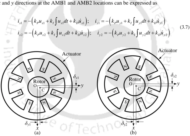
The unbalance force due to disc1 and disc2 on the rotor, in the x and y directions, can be written as. In the perfect alignment condition as shown in Figure 3.3, the force due to AMB1 on the rigid rotor in the x and y directions can be written as Following Equation (2.7), the expressions for controlling current in the x and y directions at the AMB1 and AMB2 locations can be expressed as
Equations of Motion of the Misaligned Rotor System considering Gyroscopic
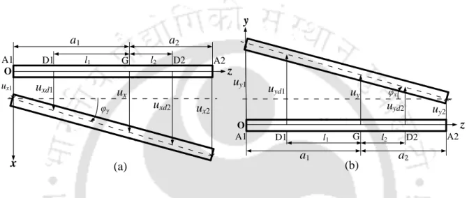
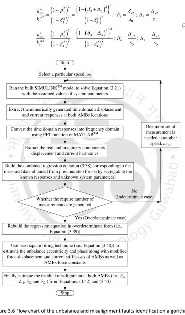
The vibration-induced displacement vector of the rigid rotor at both AMB locations is given by Now equation (3.21), representing residual and additional trial error adjustments, respectively, can be solved using SIMULINKTM to generate the system displacement and current responses in the time domain at both AMB locations. The real and imaginary parts of the complex frequency domain rotor displacement and current responses at both AMBs, for without and with sample misalignment, will be further exploited in the identification algorithm.
Development of Identification Algorithm
Since the real and imaginary components of disc eccentricity are common in equations (3.36) and (3.37) for the remaining and additional cases of experimental misalignment, the two equations can be combined to have unique values of the eccentricity parameters. To estimate all determinable parameters by inverse Moore-Penrose, equation (3.39) can be expressed in matrix form as Following the same procedure, it is possible to determine the values of deflections δx2 and δy2 between the rotor and AMB2 in the x and y directions using the ratio of equations (3.11) and (3.15).
Generation of Simulated Responses and Parameters Estimation
- Dynamic Influence of AMB Residual Misalignment on the Rotor Performance.108
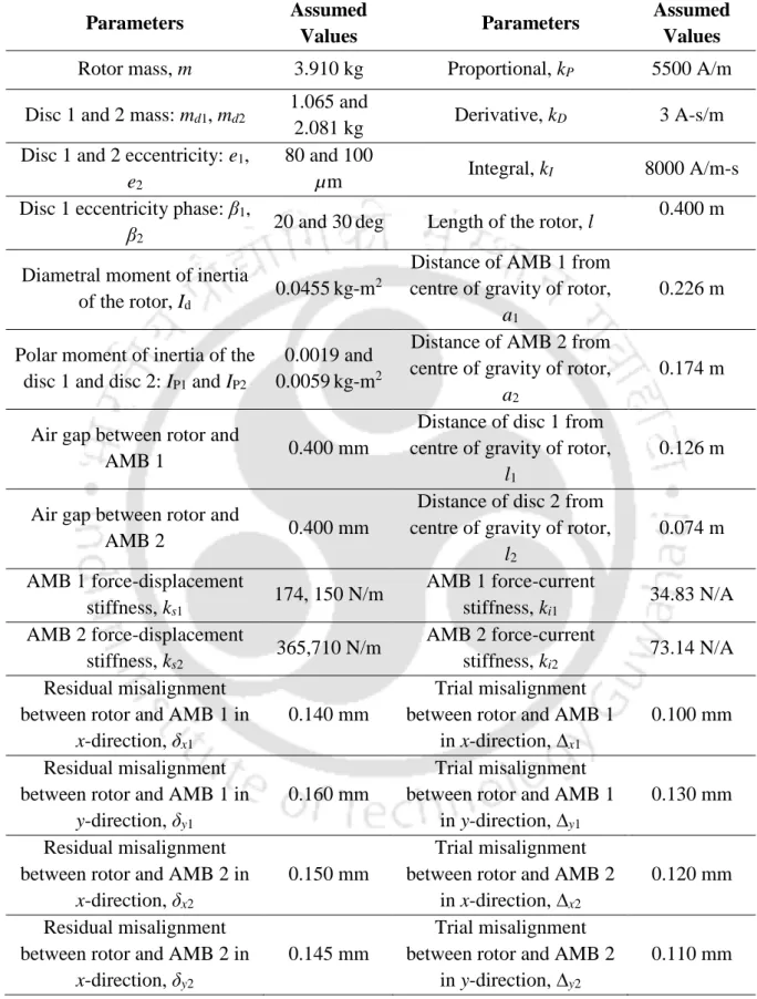
From Table 3.2, it can be observed that the maximum displacement and current responses of the rotor system at both AMB locations for without and with misalignment are higher at 35 Hz than at 30 Hz. Table 3.3 shows that the highest values of the rotor displacement and current responses in the frequency domain at the AMB1 location for the remaining misalignment are 1.47×10⁻⁴ m and 0.93 A, respectively, at an angular frequency of 30 Hz. Similarly, the maximum values of rotor displacement and current in the frequency domain for AMB2 are at the same angular frequency.
Summary
The results show that the new trial discrepancy approach associated with the developed model-based identification algorithm gives excellent estimates even with the addition of noise and modeling errors. The analysis is explored using the rotor under the critical speed of the first flexible mode of the system. Furthermore, in addition to the different nature of each AMB, the AMB will also be considered anisotropic in nature (ie, the stiffness constants in the two orthogonal directions will be different).
Introduction
The Moore-Penrose inverse technique will be used to determine the optimal solution of the identification equation.
Modelling Configuration of the Flexible Rotor System and Assumptions
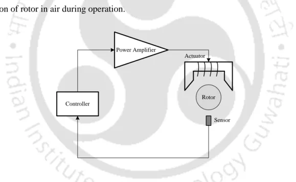
In addition, the actual force-displacement and force-current stiffness coefficients of AMBs (for perfect alignment condition) will also be identified. AMBs are assumed to have the linearized force-displacement and force-current stiffness in two orthogonal transverse directions. For stability and control of rotor system performance, a PID controller has been used in AMBs.
Finite Element Formulation of Misaligned Rotor-AMB Model
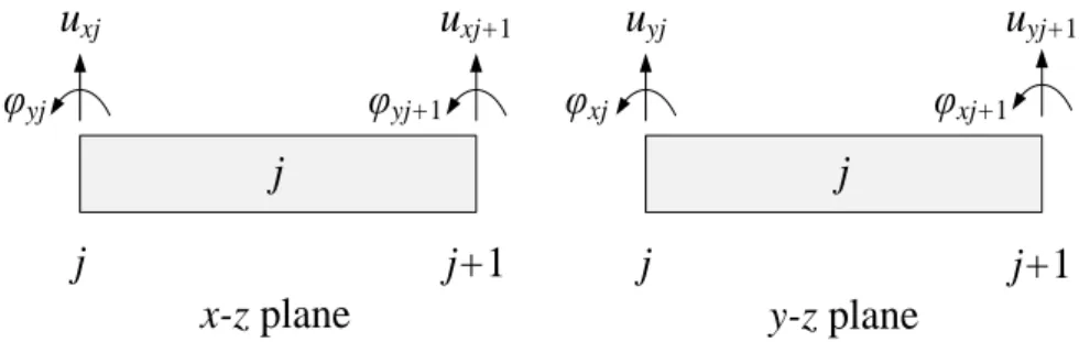
- Flexible Shaft sub-model
- Rigid Disc sub-model
- AMB Force sub-model for Residual and Additional trial misalignments
- Global Equations of Motion of the Misaligned Flexible Rotor System
- Gyroscopic Dynamic Condensation Method
In vector and combined form, the misalignment force AMB for residual and additional test distortions can be expressed as The control current vector for the PID controller in the fault case can be expressed as. The fitted equations of motion of the unbalanced and faulted rotor-AMB system for residual and additional test distortions can be written as.
Identification Scheme for Estimation of the Unbalance, Misalignment and AMB
Substituting for the unknown vectors of equation (4.25), equation (4.30) can be written in extended form, as. Equation (4.28) has a complex form and can therefore be separated into its real and imaginary components and written as. Equation (4.34) can be expressed in the combined form, to get an estimation equation for the overall imbalance and misaligned AMB parameters, such as.
Numerical Experiments and Identification
- Simulated Responses and Dynamic Effect of Residually Misaligned AMBs
- Quantitative Estimation of Unbalance and AMB Misalignment Parameters
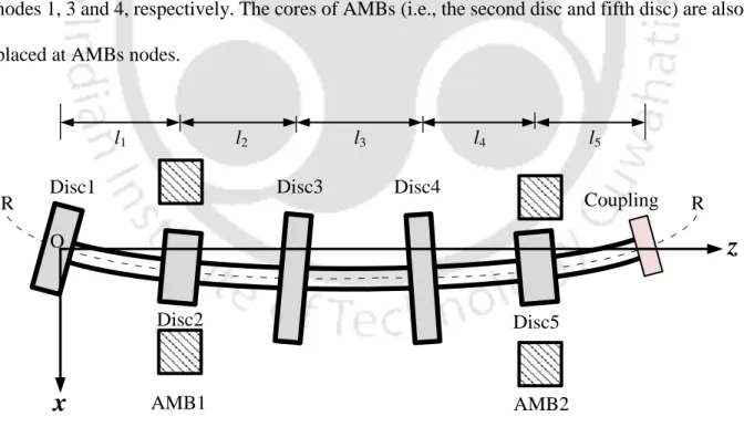
Nodes 2 and 5 are the locations of AMB 1 and AMB 2 in the considered flexible rotor AMB system. These percentage steps are 46.99% and 388% for the rotor displacement and AMB current, respectively. For the considered flexible rotor AMB system, as shown in Figure 4.4, the number of equations in the regression matrix A(ω) turns out to be only 28.
Summary
The equations of motion for each sub-model (shaft, discs, and faulted AMB force model) are presented individually and further added together to obtain a global equation of motion of the rotor-AMB system. The equation of motion is numerically simulated to obtain the displacement and current responses in the time domain at higher rotational speeds. The developed identification algorithm is also found to be effective and robust when tested against different levels of noise errors in the response and modeling errors in the rotor parameters.
- Introduction
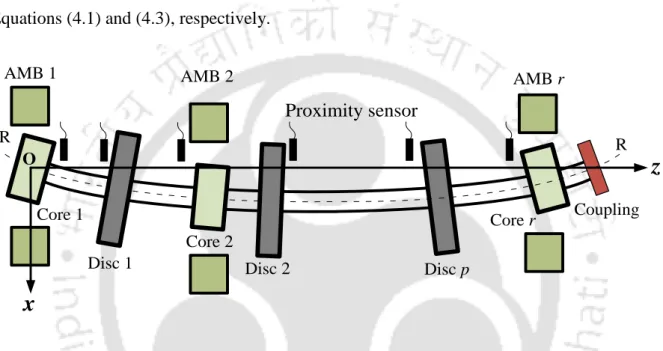
- Misaligned Flexible Rotor-Sensor-AMB System Configuration
- AMB Force sub-model for Residual and Additional Trial Misalignments
- Virtual Trial Misalignment (VTM) approach
- Misaligned Sensor sub-model for Residual and Additional Trial Misalignments176
- Results and Discussion
- Dynamic Influence of AMB and Sensor Residual Misalignments
- Identification of Unbalance, AMB and Sensor Misalignment Parameters
- Summary
Mathematical modeling for non-contact displacement sensors from the center of the rotor has been presented and even offset amounts are identified using this new approach. The dynamic effect of residual sensor and AMB mismatch on the rotor system is also investigated. Rotor misalignment with respect to supported AMBs and non-contact eddy current probes is described in more detail in the next section.
Summary of the Present Work
Conclusions from the Present Work
Main Contribution of the Present Work
Limitations and scopes of future work