The reinforcement of the beams is done with different amounts and configurations of GFRP plates. Experimental data on load, deflection and failure of each of the beams were obtained.
CHAPTER -1
INTRODUCTION
- GENERAL
- STRENGTHENING USING FRP COMPOSITES
- ADVANTAGES AND DISADVANTAGES OF FIBER COMPOSITE STRENGTHENING
- ADVANTAGES
- DISADVANTAGES
- PRESENT INVESTIGATION
This is often required when the use of the structure changes and a higher load carrying capacity is required. Corrosion of the steel reinforcement in reinforced concrete (RC) structures affects the strength of both the steel and the concrete.
CHAPTER -2
LITERATURE REVIEW
INTRODUCTION
This chapter presents an introduction to the strengthening of reinforced concrete (RC), prestressed concrete and steel members using externally bonded steel plates or composite plates and fibre-reinforced polymer (FRP) plates, with an overview of the most important research reported in the literature. In addition, a section is devoted to shear strengthening of RC members using FRP plates and sheets.
EXTERNAL STRENGTHENING USING STEEL PLATES
- INTRODUCTION
- STRUCTURAL INVESTIGATIONS
- PLATE SEPARATION AND ANCHORAGE
- DISADVANTAGES OF EXTERNAL STRENGTHENING USING STEEL PLATES
In addition, the bending stiffness of the plate increases, thereby increasing the peel stress normal to the beam. This is especially true towards the ends of the slabs where anchorages are required due to the high bending stiffness of the slab.
EXTERNAL STRENGTHENING USING COMPOSITE MATERIALS
- INTRODUCTION
- REVIEW OF EXPERIMENTAL INVESTIGATIONS
- PRESTRESSING COMPOSITE PLATES FOR STRENGTHENING CONCRETE BEAMS
- STRENGTHENING OF REINFORCED CONCRETE MEMBERS IN SHEAR
The slab prestress prevented cracks in the adhesive layer, a phenomenon associated with shear cracks in the concrete. An increase in concrete cracking under load and yielding of the internal steel was also observed.
APPLICATIONS OF FRP STRENGTHENING
A representative sample of the joint was tested in the laboratory to verify the technique prior to field use. Stopping Corrosion of Internal Steel Reinforcement of Concrete Girders in Wakayama Oil Refinery Coastal Wharf;. Longitudinal reinforcement of the sides and soffit of the culvert on the Fujimi Bridge in Tokyo.
STRUCTURAL ADHESIVE BONDING
- TYPE OF STRUCTURAL ADHESIVES
- REQUIREMENTS OF THE ADHESIVE FOR PLATE BONDING
- TESTS TO MEASURE STRUCTURAL ADHESIVE BOND STRENGTH
Reinforcement and stiffening of the concrete lining of the Yoshino Route tunnels on Kyushu Island, necessitated by cracks caused by unexpected fluctuations in underground water pressure. Curing of the cured adhesive can be achieved through the inclusion of a dispersed rubbery phase that absorbs energy and prevents crack growth. It was found that all epoxy compound joints failed due to shearing of the concrete directly below the joint surface under comparable loads.
CRITICAL OBSERVATIONS FROM LITERATURE REVIEW
Karbhari and Engineer (1996) describe the use of a modified peel test for composite-to-concrete adhesion studies in which a composite strip is pulled away from the concrete at a known angle and at a controlled rate.
OBJECTIVES OF THE STUDY
CHAPTER -3
MATERIALS AND METHODS
MATERIALS AND METHODS
MATERIALS .1 CONCRETE
- Cement
- Fine aggregate
- Coarse aggregate
- Water
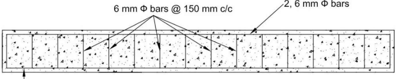
- REINFORCEMENT
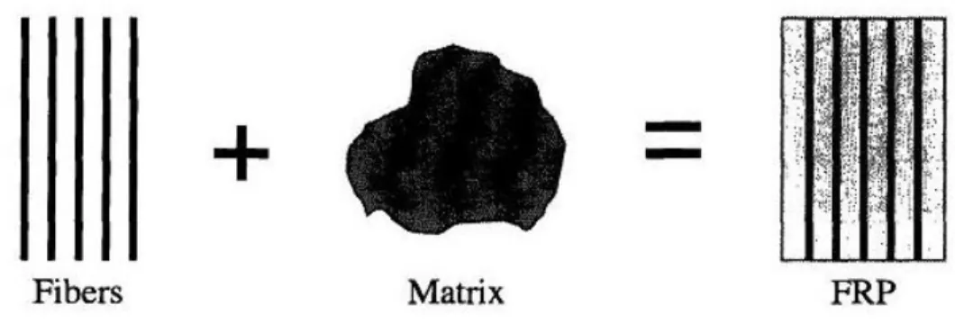
- FIBER REINFORCED POLYMER (FRP)
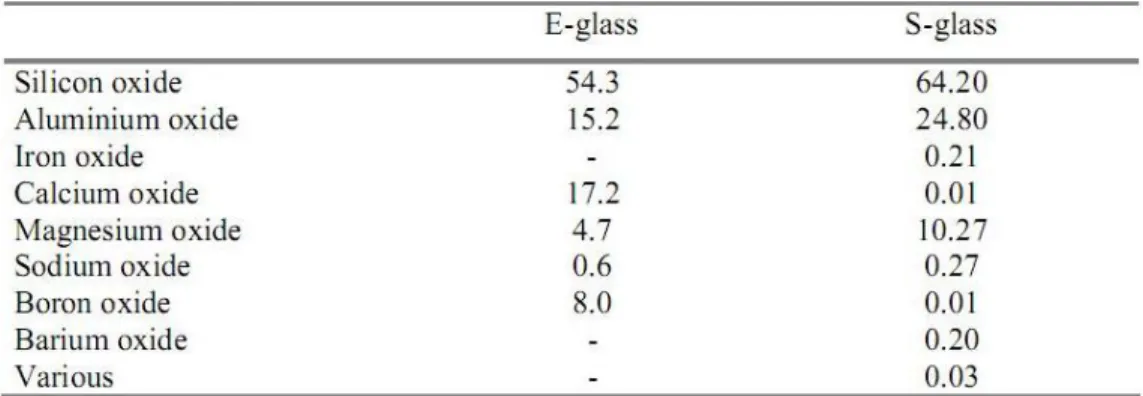
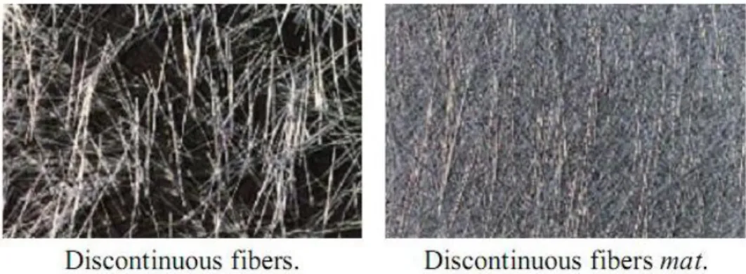
- Fiber
- Fiber sheet
- TYPES OF MATRIX MATERIALS
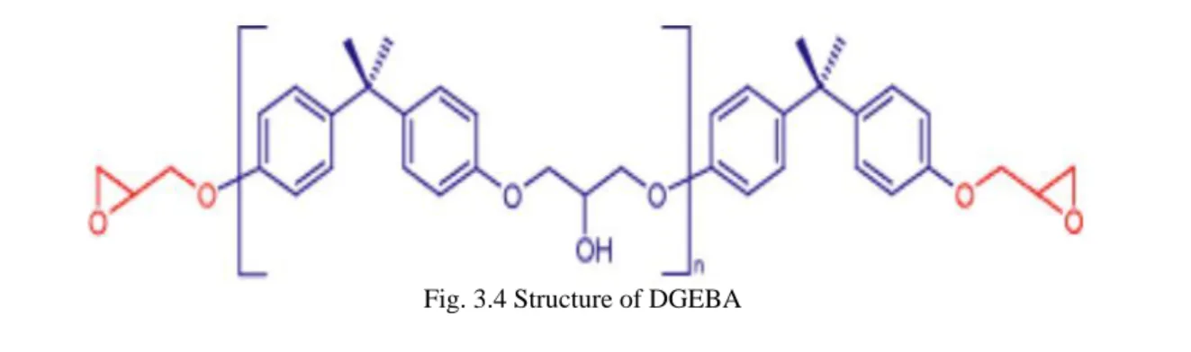
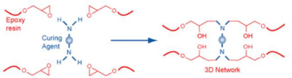
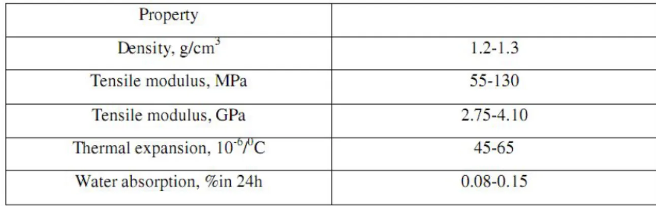
- Epoxy resin
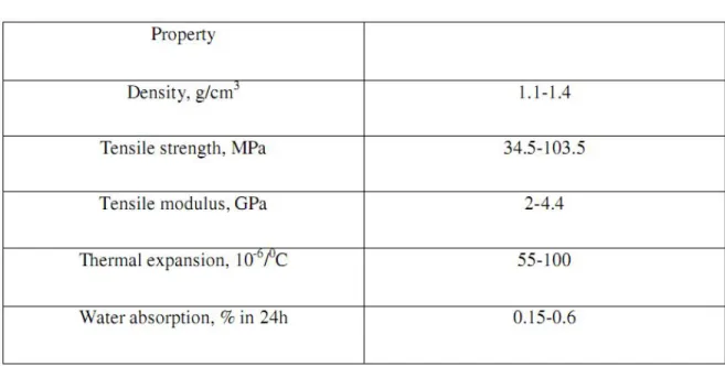
- Unsaturated polyester resins
- Adhesives
Much of the Earth's surface is sandy, and this sand is mostly quartz and other sand. Such treatments are useful to improve the durability and fatigue performance (static and dynamic) of the composite material. The success of the reinforcement technique largely depends on the performance of the epoxy resin used.
EXPERIMENTAL STUDY
Any surface treatment must be carried out immediately before FRP application takes place to prevent surface recontamination. The presence of moisture in the support must be avoided during FRP application; the surfaces of the support must be completely dry before applying the glue.
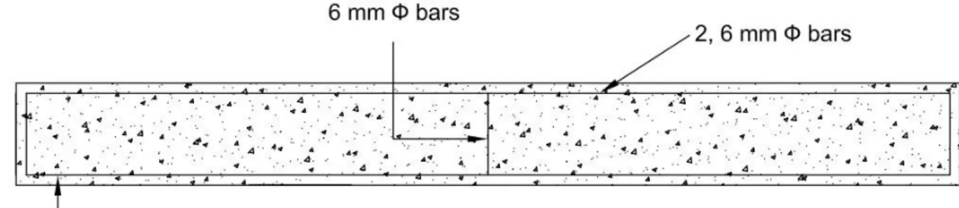
CASTING OF BEAMS
- MATERIALS FOR CASTING .1 Cement
- Fine aggregate
- Coarse aggregate
- Water
- Reinforcing steel
- FORM WORK
- MIXING OF CONCRETE
- COMPACTION
- CURING OF CONCRETE
Finally the concrete surface was leveled and finished and smoothed with metal trowel and wooden float. Concrete is dried to prevent or replenish the loss of water which is essential for the hydration process and thus for hardening. It makes concrete stronger, more durable, more impermeable and more resistant to corrosion and frost.
STRENGTHENING OF BEAMS
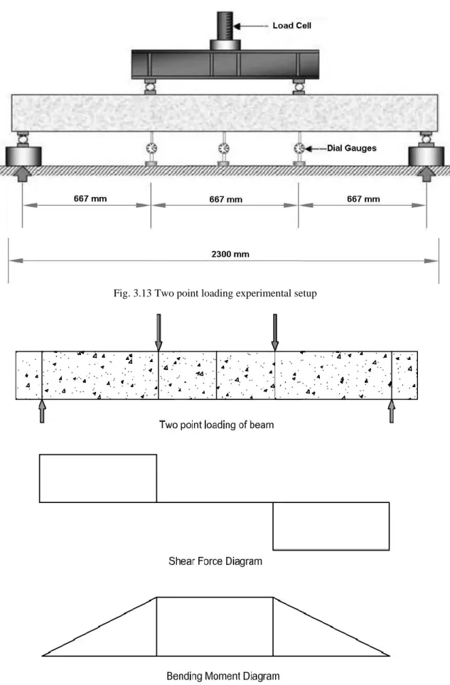
EXPERIMENTAL SETUP
- PROCEDURE
The specimen was mounted on two steel roller bearings 150 mm from the ends of the beam. One dial gauge was placed just below the center of the beam and the remaining two dial gauges were placed just below the point loads to measure the deflections. The loads are then typically increased again in similar increments until failure, with the deflection gauges being replaced by an appropriately mounted scale as failure is approached.
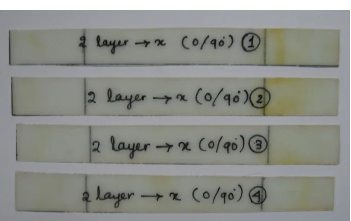
FABRICATION OF GFRP PLATE
Lamination begins with the application of gel coat (epoxy and hardener), which is applied to the mold with a brush, the main purpose of which was to provide a smooth outer surface and protect the fibers from direct exposure to the environment. Reinforcement layers were placed on the mold on top of the gel coat and the gel coat was reapplied with a brush. The hand application process was a continuation of the above process before the gel coat was fully cured.
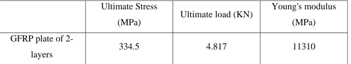
DETERMINATION OF ULTIMATE STRESS, ULTIMATE LOAD AND YOUNG’S MODULUS
The samples were cut from the plates themselves with a diamond cutter or hex saw. For Young's modulus measurement, the specimen is loaded on the INSTRON 1195 universal testing machine monotonically to failure at a recommended elongation rate (loading rate) of 5 mm/minute. Specimens were first fixed in the upper jaw and then clamped in the movable jaw (lower jaw).
CHAPTER -4
ANALYTICAL STUDY
INTRODUCTION
This chapter is devoted to the development of an analytical model for the analysis and design of reinforced concrete beams reinforced in flexibility by means of externally bonded glass fiber reinforced polymer composite plates. The purpose of this analytical model is to accurately predict the bending behavior of reinforced concrete beams reinforced with GRP plates.
FLEXURAL STRENGTHENING OF BEAMS
- ASSUMPTIONS
- CALCULATION OF MOMENT OF RESISTANCE OF THE BEAMS
Now consider the effect of strengthening beam F2 using two layers of GFRP plates, so along with the tensile force an additional tensile force will also act. Due to the application of two layers of GFRP plate at the top of the F2 beam, the moment of resistance of beam F2 is higher than the moment of resistance of beam F1. The depth of the neutral axis and the moment of resistance of both beams are presented in table 4.1.
CHAPTER -5
RESULTS AND DISCUSSIONS
RESULTS AND DISCUSSION
INTRODUCTION
FAILURE MODES
In SET I, beam F2 failed due to fracture of GFRP plate into two pieces and then flexural shear failure of the beam occurred. Beam F3 failed due to delamination of the GFRP plate after that fracture of GFRP plate occurred and then flexural shear failure of the beam. In SET II, beams S2 and S3 failed due to bending and compression of concrete on top of the beam.
LOAD DEFLECTION HISTORY
In SET I when both wrapping schemes were considered, it was found that beam F3 with GFRP sheets up to the neutral axis together with the bed had a better load-deflection behavior when compared to beam F2 with GFRP sheets only at the lower part of the beam. In SET II when both wrapping schemes were considered, it was found that beam S3 with GFRP sheet U-wrap had a better load-deflection behavior when compared to beam S2 with GFRP sheets only on the beam sides. Two-point static loading is done on the beam and at each load increment, left, right and middle deflection.
Load vs Deflection Curve for Beam F1
Beam F1 was the control beam of the SET I beams which were weak in bending but strong in shear. In beam F2, the strengthening is done by applying the GFRP sheet only in the lower part of the beam. Two-point static loading was done on the beam and at each increase in load the deflection was taken on the left, right and middle dial gauges.
Load vs Deflection Curve for Beam F2
In beam F3, strengthening is carried out by applying GFRP sheet up to the neutral axis together with the underside of the beam. Further, with increase in load, crack propagation occurred, but it had poor visibility of cracks due to the covering of the GFRP plate. Beam F3 also failed in flexural shear like beam F2, but beam F3 carried a higher ultimate load compared to both beams F1 and F2.
Load vs Deflection Curve for Beam F3
From the load and deflection data of SET I beams F1, F2 and F3, the load versus deflection curve is drawn for all three beams. From this load versus deflection curve, it is clear that beam F1 has lower ultimate load capacity compared to beams F2 and F3. Beam F2 had higher ultimate load capacity compared to control beam F1, but lower than beam F3.
Load vs Deflection Curve for Beams F1, F2 and F3
Beam S1 was the control beam of SET II beams that were weak in shear but strong in bending. Initially, only bending cracks were developed in beam S1, but eventually the beam failed due to shear.
Load vs Deflection Curve for Beam S1
In beam S2, the strengthening is done by applying the GFRP sheet only on both sides of the beam. Only flexural cracks developed in beam S2, and finally the beam failed by flexural failure and concrete crushing.
Load vs Deflection Curve for Beam S2
In the case of beam S3, the reinforcement is carried out by applying a GFRP plate as a U-wrap to the beam. Beam S3, similar to beam S2, only developed flexural cracks and finally the beam failed due to flexural failure and concrete spalling, but beam S3 carried a higher ultimate load compared to both beams S1 and S2.
Load vs Deflection Curve for Beam S3
From the load and deflection data of SET II beams S1, S2 and S3, the load versus deflection curve is plotted for all three beams. From this curve of load versus deflection, it is clear that beam S1 has a lower final load capacity compared to beams S2 and S3. Beam S2 had a higher load capacity compared to the controlled beam S1 but lower than beam S3.
Load vs Deflection Curve for Beams S1, S2 and S3
LOAD AT INITIAL CRACK
Two-point static loading was performed on both SET I and SET II beams and deflection and crack development were observed with each load increase. In beam F1, crack initiation occurs at a load of 30 KN, which is lower than beam F2.
AT INITIAL CRACK
Load at Initial Crack of SET I beams
Beams F1
Beams Details
During two-point static loading of SET II beams, deflection and crack development were observed at each load increment. In beam S1, crack initiation occurs at a load of 35 KN, which is lower than beam F2, where crack initiation started at 39.
Load at Initial Crack of SET II beams
Beams Details S1
Beams Details S1 : Control Beam
ULTIMATE LOAD CARRYING CAPACITY
The bearing capacity of the control beams and the stringer has been found out and is shown in fig. But the ductile behavior obtained by using GFRP can give us enough warning before the ultimate failure. The use of FRP can delay the initial cracking and further development of the cracks in the beam.
Ultimate load of Set I Beams
It was observed that of all the beams, the reinforced beams F2, F3 and S2, S3 have the higher bearing capacity compared to the control.
ULTIMATE LOAD CARRYING CAPACITY
Beams Details F1
Beams Details F1 : Control Beam
The ultimate load of F1 beam was 78 KN which is lower than F2 beam which carried an ultimate load of 104 KN and further lower than F3 beam which carries. The ultimate load of S1 beam was 82 KN which is lower than S2 beam which carried an ultimate load of 108 KN and further lower than S3 beam which carried an ultimate load of 122 KN.
Ultimate load of Set II Beams
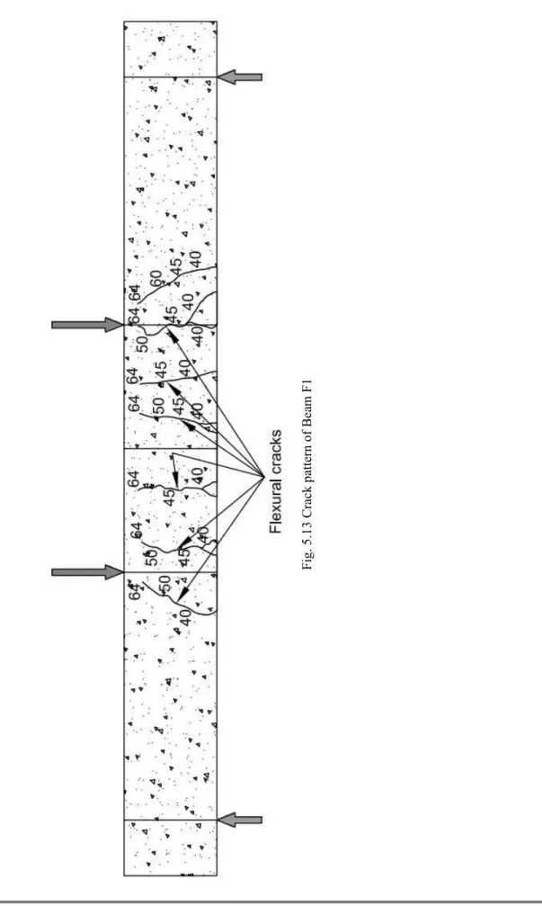
CRACK PATTERN
In SET I, the controlled beam F1 showed widely spaced and fewer cracks compared to reinforced beams F2 and F3. This compound action has resulted in a failure mode shift from bending fracture (steel compliant) in the case of controlled beam F2 to peeling off GFRP sheet in the case of reinforced beams F2 and F3. The debonding of GFRP sheets has occurred due to bending cracks by giving cracking sound.
COMPARISION OF RESULTS
CHAPTER -6
CONCLUSIONS
Flexural strengthening up to the neutral axis of the beam increases the ultimate load-carrying capacity, but the cracks developed were not visible until a higher load. The final failure is flexural failure indicating that the GFRP sheets increase the shear strength of the beam. When the beam is strengthened by U-sheathing in the shear zone, the ultimate load carrying capacity is increased by 48 % compared to the control beam S1 and by 13%.
Saleh "Reinforcement of Reinforced Concrete Beams Using Fiber Reinforced Polymer (FRP) Laminates" ACI Structural Journal/September-October 1999. McCurry "Behaviour of Full-Size Reinforced Concrete Beams Post-Fibered for Shear and Flexure with FRP Laminates "Composites: Part B. Increasing Bending Capacity of Reinforced Concrete Beams with Carbon Fiber Reinforced Polymer Composites" ACI Structural Journal/January-February 2003.