I hereby declare that the matter embedded in this thesis is the result of investigations carried out by me at the Center for Energy, Indian Institute of Technology Guwahati, Guwahati, Assam, India, under the supervision of Dr. In accordance with the general practice of reporting scientific observations, due acknowledgment has been made where the work described is based on the findings of other investigators. It is certified that the work contained in the thesis entitled "Synthesis and characterization of Nafion Composite Membrane for Reduced Methanol Crossover in DMFC", by Mrs.
Lepakshi Barbora (Roll No. for the award of the degree of Doctor of Philosophy, was carried out under my supervision and this work has not been submitted elsewhere for a degree.
Preface
The chapter will help future researchers to formulate a goal to further improve DMFC performance.
Acknowledgement
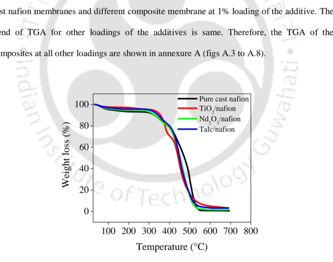
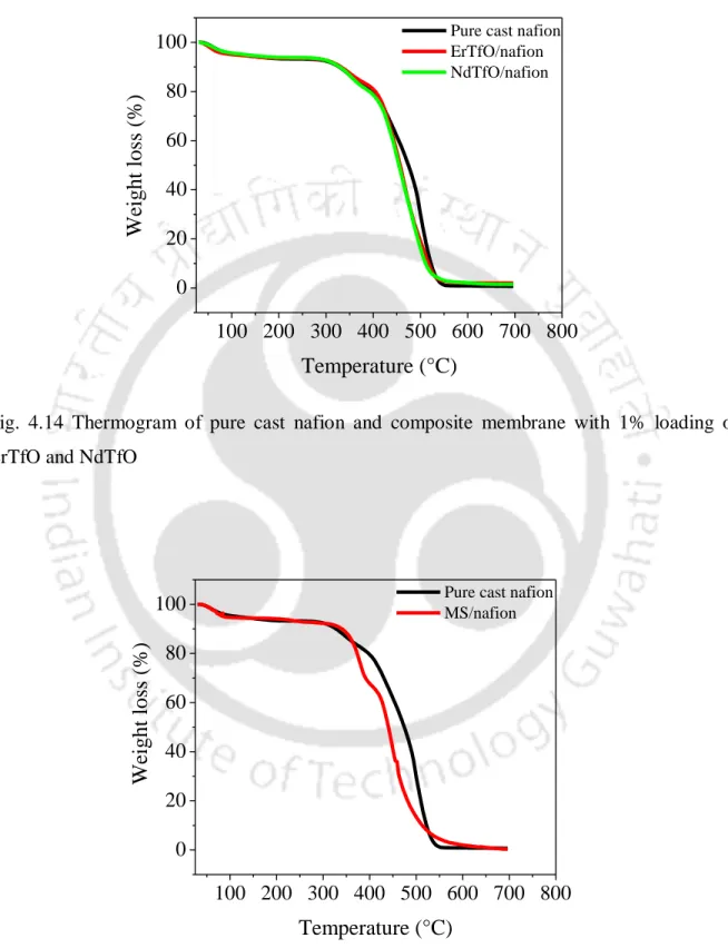
SEM images of the membranes showed the formation of dense nafion composite membranes without pore formation. XRD analysis of the nafion composite membranes showed that the TiO2/nafion and talc/nafion membranes are more crystalline than the pure cast nafion membrane. The TGA thermograms of the nafion composite membranes showed that all the composite membranes were stable up to a temperature of 310 °C.
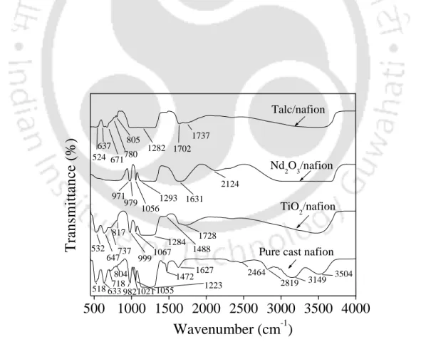
FTIR analysis of the composite membranes indicated shifting of S-O stretching and water stretching frequency peaks to higher wavenumbers and broader water bending vibration peak for the composite membranes compared to pure cast nafion membrane. Ion exchange capacity, water uptake and methanol uptake of the composite membranes were generally higher than pure cast nafion membrane. Comparison of the oxidative stability of the membranes showed that the composite membranes with lower additive loadings were chemically more stable than pure cast nafion membrane, although the optimal loading percentage varied for each type of additive.
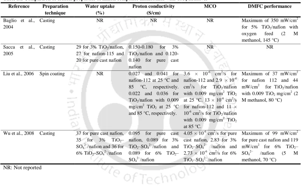
The composite membranes exhibited higher power density than the neat cast nafion membrane attributed to the decreased MCO and increased proton conductivity. Composite membranes reduced MCO by up to 80% compared to pure cast nafion membrane.
Contents
List of tables
List of symbols
List of abbreviations
Introduction
- Brief history of fuel cell
- Basic principle of direct methanol fuel cell
- Nafion membrane
- Routes to nafion modification
Therefore, fuel cell is recognized as one of the promising candidates for next generation power conversion devices for transportation, stationary and portable applications [Dillon et al., 2004]. The principle of the fuel cell was discovered by the German scientist Christian Friedrich Schönbein in 1838 [Wand, 2008]. Based on his work, the first fuel cell was demonstrated by the Welsh scientist and lawyer Sir William Robert Grove in 1839 [O'Hayre et al., 2004].
However, GE continued to work on its proton exchange membrane fuel cell (PEMFC) units, and by the mid-1970s water electrolysis technology using a polymer electrolyte membrane (PEM) had been developed for the US Navy's oxygen plant [Appleby, 1996]. In 1990, the Jet Propulsion Laboratory in Pasadena, California, in collaboration with the University of Southern California, developed direct methanol fuel cells (DMFCs) as a variant of PEMFCs [Surampudi et al., 1994]. According to the cluster network model (Figure 1.1), the morphology of hydrated Nafion shows the formation of spherical clusters (pores) connected by short, narrow channels.
One of the main limitations of Nafion is the passage of methanol (MCO) through the Nafion membrane from the anode to the cathode side [Tricoli, 1998]. Easton et al., (2003) impregnated PPy by in situ polymerization and polymerization in hydrogen peroxide with Fe(III) as an oxidizing agent (in situ polymerization, peroxide is used as a free radical initiator, PPy was impregnated with and without Fe( III) as an oxidant).
![Fig.1.2 Illustration of Yeager and Steck’s three region model of nafion [Yeager and Steck,1981]](https://thumb-ap.123doks.com/thumbv2/azpdfnet/10495233.0/46.893.129.757.109.946/illustration-yeager-steck-region-model-nafion-yeager-steck.webp)
Literature Review
- Hygroscopic additives
- Bi-functional additives
- Methanol impermeable and/or proton conducting additives 1. Nafion composites with palladium (Pd) additives
- Summary of literature review
- Aim and objectives
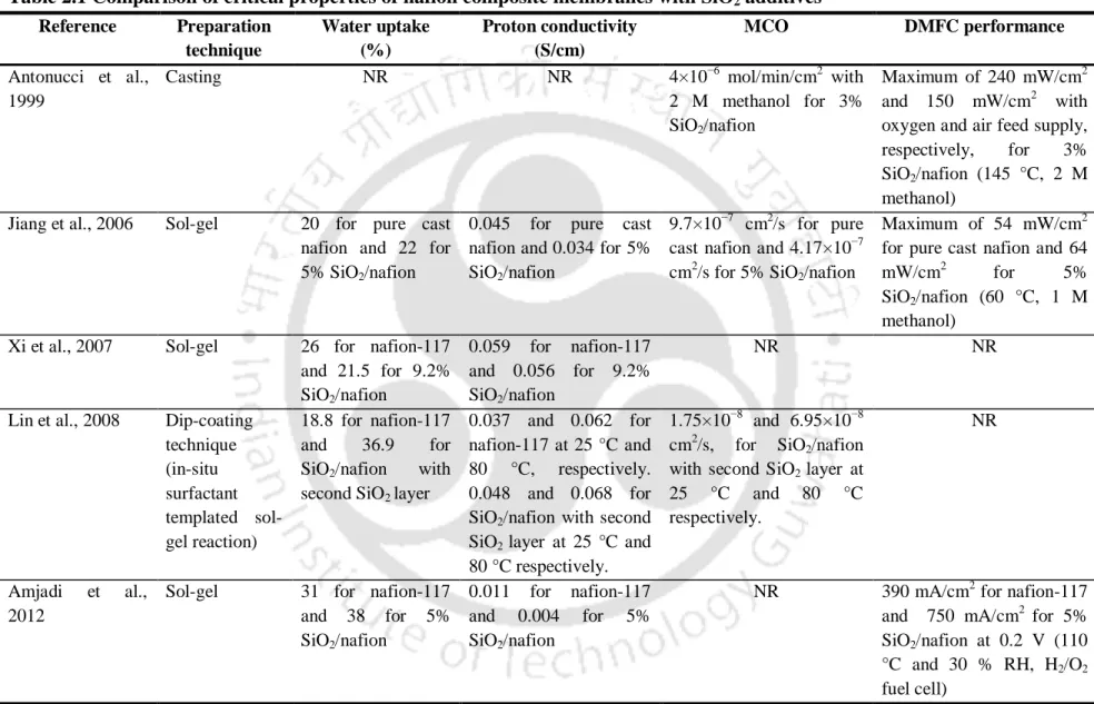
According to Xi et al. (2007), SiO2/nafion membranes prepared using sol-gel were successfully used in DMFCs due to the simple handling process and lower MCO attributed to the filling of the polar clusters (pores) of the unmodified Nafion membrane. with SiO2 nanoparticles during the in situ sol-gel reaction with TEOS. In addition, the thermal stability of the composite Nafion membrane was improved along with higher water uptake than pure cast Nafion [Jiang et al., 2006]. However, the proton conductivity of the SiO2/nafion membranes was found to be slightly lower than that of the pure cast nafion membrane.
Tang et al., (2007) reported that by optimizing the SiO2 content in SiO2/nafion membrane or by using organically modified silicate (ORMOSIL) to replace SiO2, the performance of the nafion composite can be further improved . The improved proton conductivity of the composite membrane was attributed to the hygroscopic property and proton conductivity of TiO2. However, the stability of the phosphoric acid group on 3-APTES has not been evaluated [Kang et al., 2008].
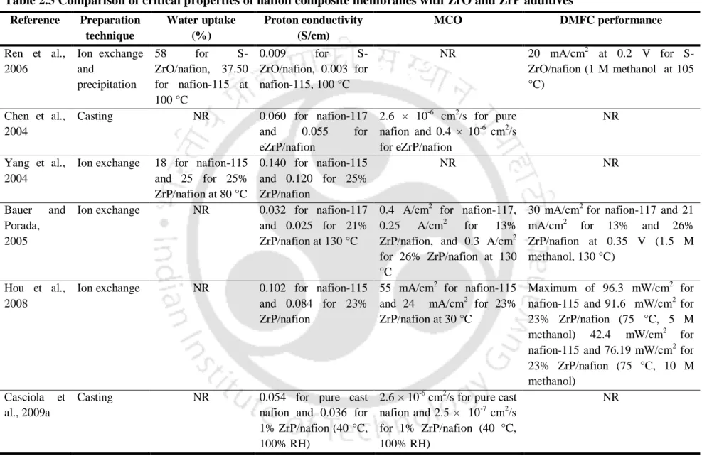
However, the proton conductivity of the composite membranes was 0.055 S/cm slightly lower than pure cast nafion membrane (0.06 S/cm). As a consequence of the higher elastic modulus values, the composite membranes exhibited enlarged stability range at higher temperature and RH values compared to the nafion-117 membrane [Casciola et al., 2008]. However, the polarization curve of the nafion composite in a DMFC was slightly reduced compared to the nafion-117 membrane.
Subsequent treatment with phosphoric acid improved the elastic modulus, but reduced the conductivity of the composite membranes compared to nafion-117 [Casciola et al., 2008]. The fuel cell performance of the SiWA/nafion membrane in an H2/O2 cell was inferior compared to nafion-117. However, the nafion composites with inorganic additives such as titanium dioxide (TiO2) and tungsten oxide (WO3) accelerated the decomposition of the composite membrane at an earlier temperature than pure cast nafion membrane [Shao et al., 2006].
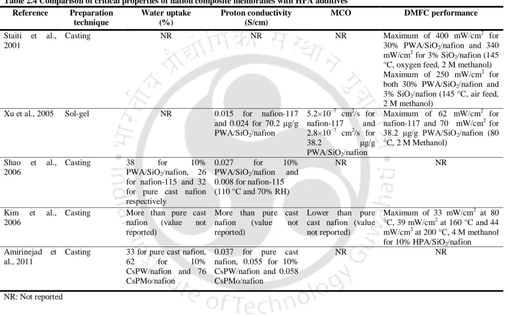
Increased proton conductivity of the composite membranes was found, which can be attributed to the hygroscopic nature of CsHPs [Amirinejad et al., 2011]. However, both the MCO and proton conductance of the nafion composite membranes were lower than those of nafion-117 and pure cast nafion membrane. Rhee et al., (2005) synthesized nafion composites with organic sulfonic acid group-modified MMT (HSO3-MMT).
Experimental
- Materials
- Crystalline, hygroscopic additive
- Bi-functional additive
- Synthesis of membrane .1 Pure cast nafion membrane
- Composite nafion membrane
- Treatment of membrane
- Characterization of additives .1 Particle size analysis
- Characterization of membrane
- Fuel cell testing
- Fabrication of MEA
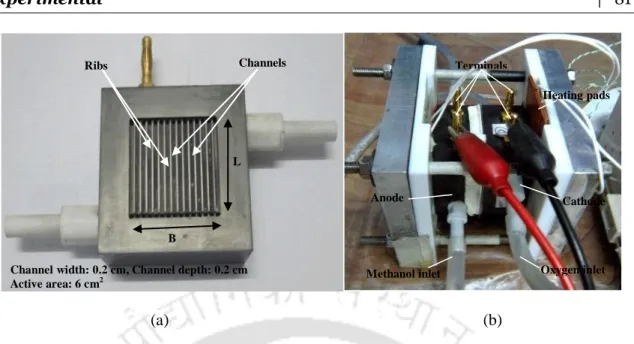
- Fabrication of DMFC setup
- Performance evaluation of DMFC
The chemical structure of MS is shown in Figure 3.5 and the general properties of the 3A MS are given in Table 3.5. After the membrane was thoroughly characterized ex-situ, the membrane was used in the direct methanol fuel cell (in-situ characterization) to evaluate the fuel cell performance. The detailed procedure for the fabrication of the membrane electrode assembly (MEA) and the characteristics of the fuel cell are given in the relevant sections.
Surface morphologies of the additives used in the study were evaluated using scanning electron microscope (make: LEO; model: 1430vp). The thickness of the membrane was kept the same for all the experiments, unless otherwise stated. Thermal behavior of the membrane was studied using a thermogravimetric analyzer (make: Mettler Toledo; model: SDTA 851e).
C/min was used in the range of 25-800 °C in a nitrogen atmosphere to study the thermal behavior of the membrane. The transmission spectrum of the membrane was recorded in the spectral range 450-4000/cm2 with a resolution of 4/cm [Barbora et al., 2009]. Here, H+ from the sulfonic sites of the membrane was replaced by Na+ using a NaOH solution.
The water absorption of the membrane was evaluated by suspending a dry membrane sample of known weight in deionized water for 24 hours. The weight of the wet membrane sample was measured and the water absorption of the membrane was calculated by eq. Oxidative stability was characterized by immersing the membrane in a 3% H2O2 solution at 80 °C and measuring the weight of the membrane over time [Fu et al., 2008;
The proton conductance of the membrane through the plane was determined in the conductance cell shown in Fig. The fuel cell was used to study and compare the I-V performance of the membranes, as discussed in the following sections. Temperature-controlled silicone heating pads were attached to opposite sides of the plates as shown in the figure.
Results and Discussion
- Characterization of additives .1. Particle size analysis
- Scanning electron microscopy (SEM) analysis
- Characterization of membrane
- Oxidative stability
- Selectivity
- Performance evaluation of DMFC using membranes .1. Effect of additive loading on DMFC performance
By comparing the XRD patterns of the neat cast nafion and the TiO2/nafion membrane, it can be concluded that the crystallinity of the nafion membrane increased with the incorporation of TiO2. It can be seen that above 360 °C the degradation of the composite membrane is faster than the pure cast nafion membrane. It can be seen in the figure that the thermograms of the nafion composites are almost similar to the pure cast nafion membrane with no significant change in thermal stability.
However, above 440 °C onwards, the degradation of the composite membrane was higher compared to the pure cast nafion membrane. FTIR spectra were obtained to find out the changes in the structure of composite membranes upon incorporation of the additive compared to the pure cast nafion membrane. The shift of the bending frequency is due to the increase in hydrogen bond strength [Mizuno et al., 1997].
The FTIR results of the MS/nafion membrane also indicate the increased water content compared to the pure cast nafion membrane, which is in agreement with the water absorption results found in the later part of the thesis. However, a further increase in the additive loading forms agglomerates of the additive in the composite membrane. The increased water absorption can be attributed to the hygroscopic nature of the additives [Watanabe et al., 1996].
Therefore, the water absorption of the neat cast nafion membrane increased with the addition of the additive. The degradation rates of the composite nafion membrane using TiO2, Nd2O3 and talc are shown in fig. However, in every composite (except 9% TiO2) the degradation rate of the composite was lower than the cast nafion membrane.
The maximum proton conductivity varies with the loading of the additive for the nafion composites. This can be attributed to the surface modification by the crystalline talc, which created obstruction in the flow channels of the composite membrane. Figures 4.52 to 4.54 show the effect of temperature on MCO of pure cast nafion membrane and composite membrane with 1% loading of the additives (representative result).
In addition, the relative selectivity of the composite membranes with respect to the pure cast Nafion membrane is shown in Fig. However, it can be seen that the properties of the composite are superior to the pure cast Nafion membrane.
![Table 4.1 Volume median diameter [D(v,0.5)] for TiO 2 , Nd 2 O 3 , talc, and MS](https://thumb-ap.123doks.com/thumbv2/azpdfnet/10495233.0/122.918.101.790.153.523/table-volume-median-diameter-for-tio-nd-talc.webp)