This is to confirm that the thesis entitled 'Development of Gasifier for Diesel Engine Fueling' submitted by Deepali Rath (107ME065) partially meets the requirements for the award of a Bachelor of Technology Degree in Mechanical Engineering at the National Institute of Technology, Rourkela is an authentic work done by her under my supervision and guidance. The design of the entire gasifier and the details of each part are provided. The diesel engine ran with diesel as the main fuel and the production gas extracted from biomass was sent with air.
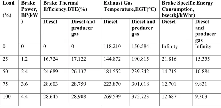
A reduction in the consumption of diesel fuel was observed as the brake specific energy consumption was found to decrease when both diesel and producer gas were used. Also, a marginal increase in thermal efficiency was noted with the use of producer gas along with diesel fuel. Performance characteristics of diesel engine with diesel as fuel and diesel with producer gas as fuel.
Combustion characteristics for diesel engine with diesel as fuel and diesel together with producer gas as fuel.
INTRODUCTION
ENERGY SCENARIO IN INDIA
India is currently the eleventh largest energy producer in the world, accounting for nearly 2.4% of the world's total energy production and 3.7% of the world's total annual energy consumption, making it the sixth largest energy consumer. Electricity production in India is highly dependent on energy sources from coal, hydropower and natural gas. To meet the ever-increasing demand, energy imports such as oil and natural gas have increased.
RENEWABLE ENERGY TECHNOLOGIES IN INDIA
2]We must use and conserve the energy sources efficiently and also develop alternative energy sources. Renewable energy sources with their estimated potential and the current number of installations or total capacity [2]. Gaseous fuels are best suited for internal combustion engines as their ignition delay is very small.
Currently, a number of biomass fuels are being evaluated such as fuel oil made from wood, soybeans, rapeseed, etc. Conventionally, it is made by passing air and steam through a thick bed of coal or coke that varies in temperature from red hot to low temperature.
![Table 1. Renewable energy sources with their estimated potential and the present number of installations or total capacities [2]](https://thumb-ap.123doks.com/thumbv2/azpdfnet/10557689.0/14.892.126.800.228.1060/table-renewable-sources-estimated-potential-present-installations-capacities.webp)
OBJECTIVES
Various works in the field of carburetors are studied and presented. The various designs of carburetors are studied along with the advantages and disadvantages of each design and the ease of manufacturing a design. Relevant information is obtained which is useful for the design and development of the carburettor. In this chapter, the reader will know the basic principle of gasification, the thermochemical processes involved in the process, the different zones of a gasifier and about the types of gasifiers.
The material to be used for each part is determined and the entire gasifier is manufactured accordingly. In this chapter the reader is introduced to the experimental setup and the initial operation of the gasifier. The performance characteristics and combustion characteristics are studied and deductive conclusions are drawn.
In this project, the reader will be able to understand the results of the project and the future scope of work that can be done.
LITERATURE SURVEY
The experiments were designed to obtain liquid flow characteristics of the gasifier and also to obtain the temperature profile in the reactive bed, the gas composition and calorific value. When used in firing mode, the higher temperature in the bed resulted in better conversion of non-combustible component in the resulting gas and thus improved the calorific value of the product gas. The performance of the biomass gasifier system was evaluated in terms of producer gas composition, the calorific value of producer gas, gas generation rate, zone temperatures and cold gas efficiency.
Neck temperature was found to increase with feeding rate for similar ER values. The construction of the gasifier is based on the design proposed by Bhattacharya et al. 7] The various parts of the carburettor such as reaction chamber, fuel bowl, gas outlet and air inlet are designed.
The gasifier was ignited by a flame torch and the composition of the product gas was found to be in close agreement with the desired composition.
GASIFICATION
- BIOMASS CONVERSION TECHNOLOGIES
- THERMAL GASIFICATION OF BIOMASS
- CLASSIFICATION OF BIOMASS GASIFIERS Gasifiers are classified as per
- UPDRAFT GASIFIER
- DOWNDRAFT GASIFIER
- CROSS DRAFT GASIFIER
- CH\EMISTRY OF THE GASIFICATION PROCESS
- Combustion zone
- Pyrolysis zone
A number of factors decide which process to use such as the location of the source and its physical condition. Here, animal waste is pressure cooked with an alkaline catalyst in the presence of carbon monoxide. The material in a pulverized or chopped form is placed in a reactor vessel or retort and heated in the absence of air.
Various complex physical and chemical processes take place in the gasifier, which acts as a chemical reactor. In larger plants, the gas can be burned directly (e.g. in an industrial oil boiler). The area requirement for gasification equipment is the lowest per output unit of energy in the form of heat and/or electricity.
The direction of the gas flow defines it as a gas generator that produces down draft, up draft or cross draft. In upstream gasifiers, air enters below the combustion zone and the producer gas exits near the top of the gasifier. In the present work, an upstream gasifier has been designed and built due to its easy fabrication.
In this type of gasifier, air enters the combustion zone and exits the produced gas near the bottom of the gasifier. The throat, which acts as a constriction in the hearth, ensures that the gaseous products pass through the hottest zone, the gas produced contains less tar and more ash. With this type of gasifiers, the gas produced flows upward into the annular space around the gasifier, which is filled with charcoal.
Air enters the carburetor by cross draft through a water-cooled nozzle located on one side of the combustion chamber. The gas is produced in the horizontal zone in front of the nozzle and passes through the vertical grate to the hot gas opening on the opposite side. Following are the main reactions that take place in different areas of the gasifier.
Various experiments with different gasifiers under different conditions have shown that the condensate formed amounts to an average of 6-10% of the weight of gasified wood.
![Table 2. Heat content of various fuels[8]](https://thumb-ap.123doks.com/thumbv2/azpdfnet/10557689.0/22.892.115.796.367.992/table-2-heat-content-of-various-fuels-8.webp)
DESIGN AND DEVELOPMENT OF THE GASIFIER
COMPONENTS OF THE FABRICATED GASIFIER
The material used for the construction of the outer wall of the reaction chamber was 2 mm thick mild steel sheet and the outer dimension of the reactor was 36x36x44 cm. The grate on which the fuel was placed was held at a height of 22 cm from the top and the reaction chamber was supported by four legs. The wood chips were placed on the grate and filled to about two-thirds of the height of the gasifier.
For the removal of the accumulated ash, a mild steel door is provided at one end of the reaction chamber. It is attached to the reaction chamber using a hinge welded to the chamber. The top plate of the reaction chamber which had a dimension of 36x36 cm had a hole drilled in it so that the fuel tank could be attached to it.
It was fixed to the reaction chamber through threaded connections and placed just below the grate. 3. Fuel plate: It was made of mild steel sheet and was located above the reaction chamber. A circular cross-section was chosen as there were no fuel stall problems in the corners.
Gas Exhaust: The production gas formed in the reaction chamber was allowed to flow out through a ½" diameter mild steel pipe. Wood chips (sesame wood or rosewood) were used as fuel, which is a renewable form of energy and the damage to the air is reduced from injected into the gasifier at the bottom. The gas is released from the top.
The pipe coming out of the blower is equipped with the air inlet on one side of the reaction chamber. As shown in the figure, a red pipe coming from the carburettor is directed to the diesel engine. The gas coming out of the carburetor is allowed to pass through a condenser and is directed to the heat engine.
The diesel engine is started and the air along with the gas is sent to the engine.
![Table 4. Physical properties of sesame wood chips[4]](https://thumb-ap.123doks.com/thumbv2/azpdfnet/10557689.0/38.892.106.805.612.735/table-4-physical-properties-sesame-wood-chips-4.webp)
RESULTS AND DISCUSSION
- BRAKE THERMAL EFFICIENCY
- EXHAUST GAS TEMPERATURE
- COMBUSTION CHARACTERISTICS .1 IGNITION DELAY
- SUMMARY OF COMBUSTION PARAMETERS
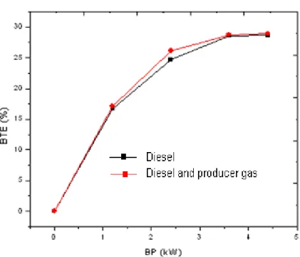
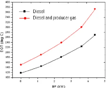
Fig. 20 gives a comparison between the thermal efficiency of engine brakes when only diesel is used as fuel and when both diesel and producer gas are used. When producer gas is used in conjunction with fuel, a noticeable increase in efficiency can be observed at various power outputs. Fig.21 shows the variation of exhaust gas temperature with braking power for both diesel as fuel and diesel together with producer gas.
This may be due to the fact that the energy supplied to the engine increases when the generator gas is sent along with the air. It was found that the specific energy consumption decreases at all power outputs when diesel fuel is used together with generator gas, which is an indication of good combustion efficiency. Figure 23 shows a comparison between the ignition delay when only diesel fuel is used and when both diesel and generator gas are used as fuel.
At lower and higher output powers, it turns out that the ignition delay is less when producer gas is sent together with air. As power increases, ignition delay decreases when producer gas is used with diesel. This may be due to a more efficient use of air when producer gas is used, thus reducing the time delay.
The maximum pressure is found to increase when diesel together with producer gas is used. The addition of producer gas increases the energy content of the fuel, which leads to an increase in the value of the maximum pressure. Table 6 shows the readings obtained to indicate the performance characteristics of the engine when diesel fuel was used and when producer gas was sent along with air.
It also shows the changes in the parameters when producer gas was used together with diesel fuel. It is also found that the brake specific energy consumption decreases when producer gas is used with diesel. At full load conditions, the brake-specific energy consumption decreases by 26.67%.