78Università di Pavia, Istituto Nazionale di Fisica Nucleare Sezione di Pavia, I-27100 Pavia, Italia. 84 Imperial College of Science Technology and Medicine, Blackett Laboratory Prince Consort Road, Londra SW7 2BZ, Regno Unito.
A Roadmap of the DUNE Technical Design Report
Executive Summary
The order of the following chapters has been chosen to first provide additional details about the organizational structures summarized here; secondly, object mappings, supporting infrastructure and context detectors; and third, information on project-related functions and methodologies used by DUNE TC focusing on the areas of integration engineering, technical reviews, quality assurance, and safety oversight. Due to their most advanced stage of development, the functional examples presented here focus primarily on the single-phase (SP) detector module.
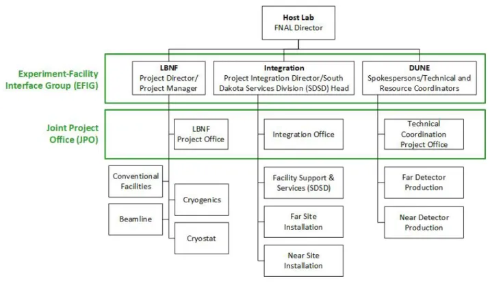
Global Project Organization
- Global Project Partners
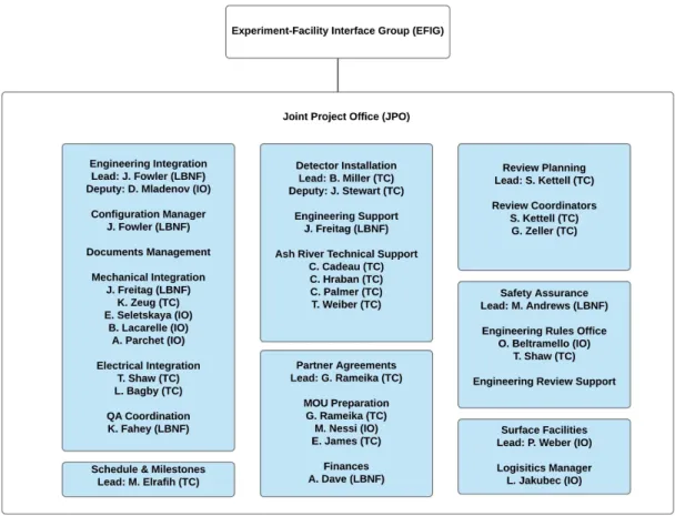
- Experimental Facilities Interface Group
- Joint Project Office
- Coordinated Global Project Functions
- Safety
- Engineering Integration
- Change Control and Document Management
- Scheduling
- Review Planning and Oversight
- Development of Partner Agreements
- ProtoDUNE Experience
EFIG is responsible for directing the integration and deployment of LBNF/DUNE deliverables and works with the consensus of its leadership team. Electrical engineers are included in the core JPO team to ensure proper integration of the detector's electrical components.
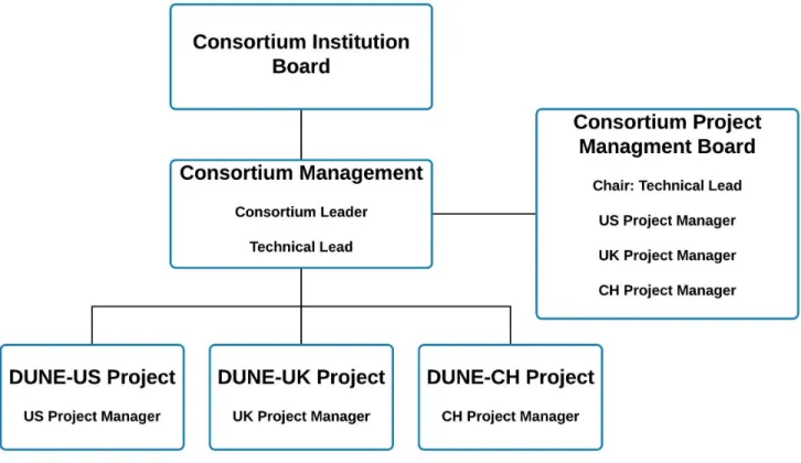
Detector Design and Construction Organiza- tion
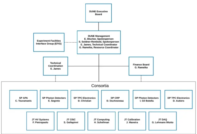
- DUNE Consortia
- DUNE Collaboration Management
- Technical Coordination
- Technical Coordination Organization
- Safety
- Engineering Integration
- Change Control and Document Management
- Schedule
- Risk Management
- Review Process
- DUNE Work Flow
A dedicated DUNE ES&H Coordinator sits in the Technical Coordination Organization and guides the DUNE Security Program under the direction of the LBNF/DUNE ES&H Manager. A dedicated DUNE QA specialist sits in the Technical Coordination Organization and coordinates the DUNE QA program under the direction of the LBNF/DUNE QA Manager.
Detector Installation and Commissioning Or- ganization
Far Site Safety
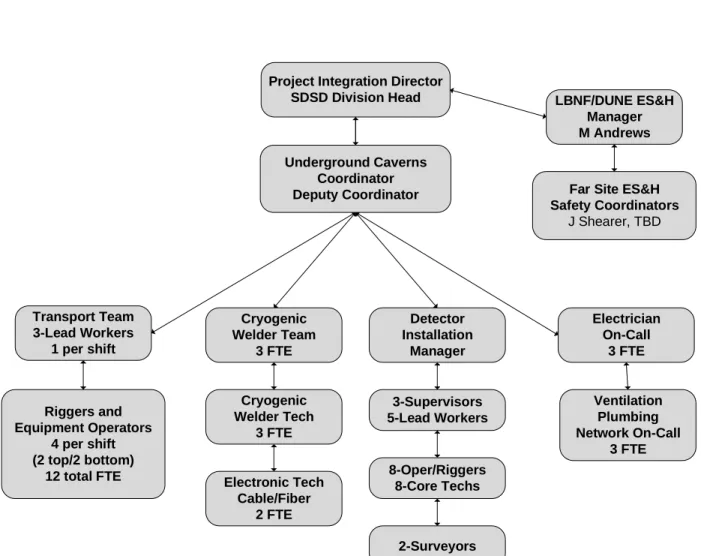
The Project Integration Director has responsibility for implementing the LBNF/DUNE ES&H program for installation activities in South Dakota. The LBNF/DUNE ES&H Manager heads the safety organization on site and reports to the Project Integration Director to support the execution of this responsibility.
Integration Office Management
- South Dakota Warehouse Facility
- Underground Caverns
- Trial Assembly at Ash River
The organization responsible for managing the contribution of the technical support team to the installation activities taking place in the underground caverns is shown in Figure 4.4. The management team oversees the technical resources assigned to the detector installation effort and works with consortium team members to maximize the overall efficiency of the installation process.
South Dakota Services Division
This structure, as illustrated in Figure 4.7, will provide a platform for conducting more detailed tests of the proposed detector installation plan. SDSD will support these activities, which are the responsibility of the Project Integration Director, by providing access to the required technical resources.
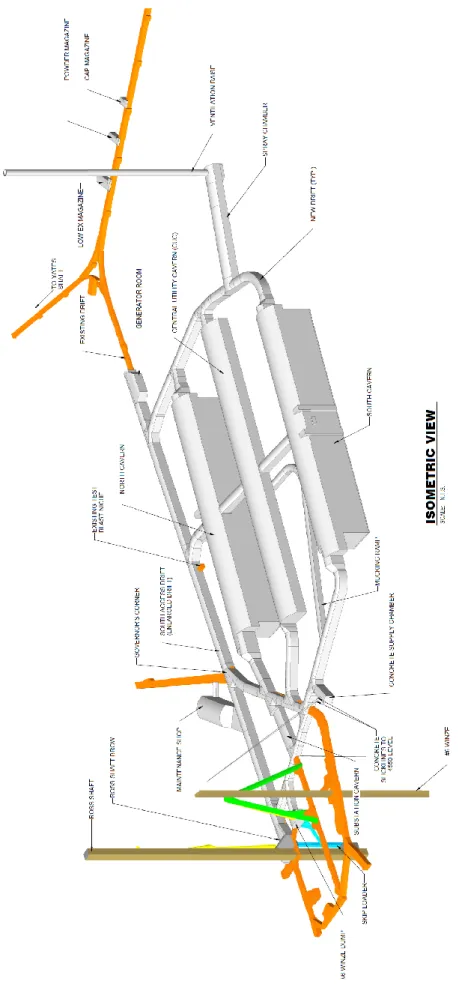
Facility Description
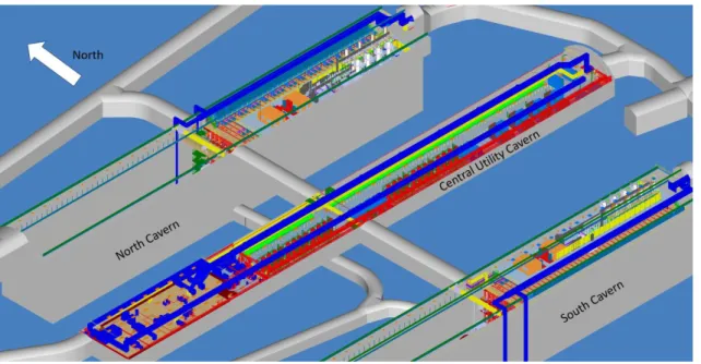
- Underground Facilities and Infrastructure
- Detector Caverns
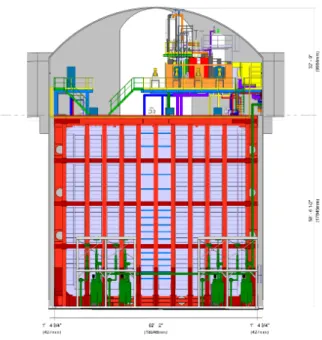
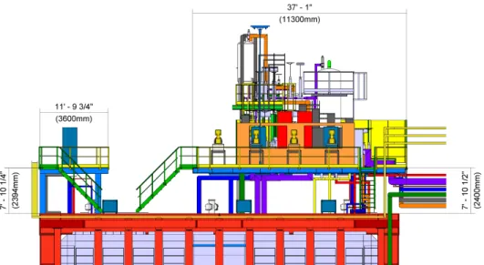
- Cryostat
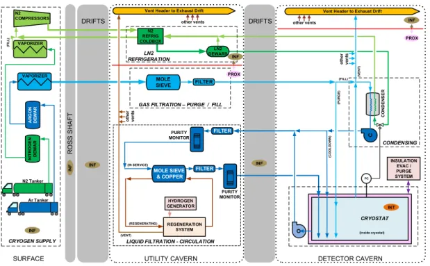
- Cryogenics
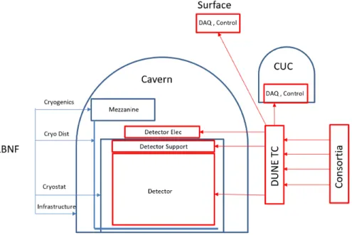
- Detector and Cavern Integration
- Detector Grounding
- Detector Power
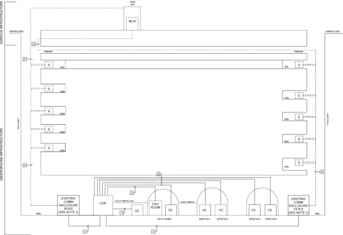
Surface (on the left), with the receiving facilities and the recycling compressors of the nitrogen system. As mentioned above, the detector ground only exists in the area of the steel container that surrounds it.
Load (kW)
Total Power (85%
DUNE - DP
DUNE Detector Electronics - Estimated Power Consumption
- Data Fibers
- Central Utility Cavern Control and DAQ Rooms
- Surface Rooms
- DUNE Detector Safety System
A total of 96 fiber pairs are routed to the underground DAQ space for use by the DUNE experiment and LBNF. The 4850L fire alarm system is connected to the surface incident command vault on the second floor of the Yates Administration building. The DDSS must communicate with the DUNE slow control system and with the 4850L fire alarm system.
DUNE Detector Construction Management
- DUNE Single-Phase Far Detector Module
- DUNE Dual-Phase Far Detector Module
- DUNE Far Detector Consortia
- Work Breakdown Structure (WBS)
There are four high voltage feedthroughs (HV) on top of the cryostat, two at each end. The DP DSS consists of a set of stainless steel cables that hang from grommets on top of the cryostat. The cryogenic front-end (FE) electronics are installed in the signal pass-through chimneys (SFT chimneys) on the roof of the cryostat to process the LArTPC signals.
DUNE
DAQ (DP-DAQ)
This level 4 structure is repeated under each of the level 3 items to ensure that the full cost of each primary detector component can be rolled up over the sequence of activities that define their design, production and installation.
DUNE Design Maturity
This was prototyped in subsequent runs of the 35 ton prototype and demonstrated in ProtoDUNE-SP (80%). The mechanical design was extensively developed using the 35 ton prototype detector and ProtoDUNE-SP (85%). The DAQ artdaq back end was developed in several experiments, including the 35 ton prototype and ProtoDUNE-SP.
Integration Engineering
Mechanical Integration Models
- Static Models
- Envelope and Assembly Models
- Integration and Interface Drawings
- Detector Survey and Alignment
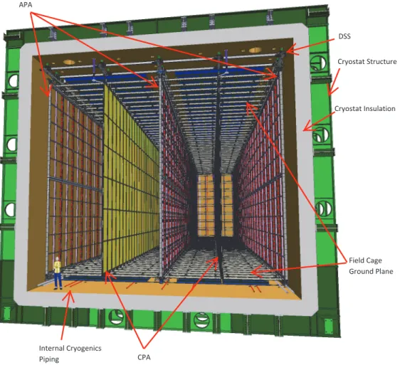
Generation of envelope models and drawings is the responsibility of the JPO engineering team in coordination with consortia. The reference plane, defined as the plane of the APA yokes, is explained in the alignment section (section 7.1.4). Before mounting the detector module, a set of cryogenic distribution tubes is installed on the floor of the cryostat.
Electrical Integration
- Electrical System Block Drawings, Schematics, Layouts and Wiring DiagramsDiagrams
- Electrical Integration Documentation
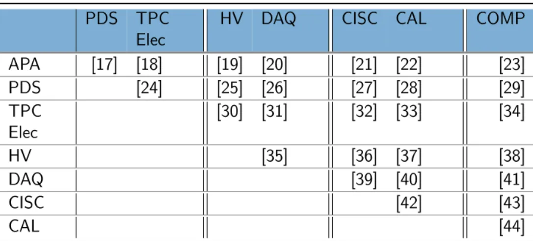
Interfaces that occur between subsystems of different consortia will be documented and formally agreed between the technical leaders of the coordinating consortia and must be verified by the JPO engineering team. Much of the documentation needed to describe a subsystem can be used for the interface documents. This additional detailed information may exist outside the primary interface document between the consortia, but that document must refer to it.
Configuration and Drawing Storage and Dissemination
Documentation required for the interface between two electrical subsystems includes a block diagram identifying all connections between the subsystems. For a signal cable, interface documentation includes the connector specifications, pins on each end of the cable, and the protrusions of the board connectors. Consortium technical leaders and the JPO engineering team sign off and approve the detailed documentation information about integration interfaces not included in the primary consortium-to-consortium interface document.
Organization of Interfaces and Interface Documents
Interface documents are developed and maintained to manage the interfaces between consortia and between each consortium and the TC. The interface documents are managed by the appropriate technical leads of the consortium and by project engineers for technical coordination. Once the technical design is complete, the interface documents are placed under revision control.
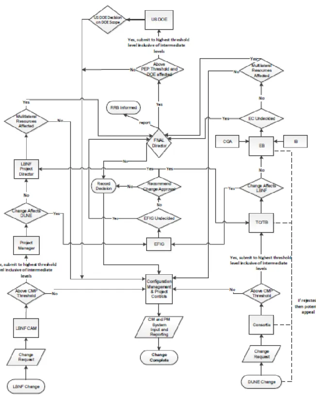
Engineering Change Control
Value Engineering
Reviews
- Design Reviews
- Production Reviews
- Installation Reviews
- Operations Reviews
- Review Tracking
- Lessons Learned
- Reporting
Regular production progress reviews will take place after production starts, depending on the length of the production process. The review process is an important part of the DUNE Quality Assurance (QA) process, as described in Section 9.7.2, for design and production. Module 0 is expected to be produced and introduced as part of the production readiness review.
Quality Assurance
Overview of DUNE Quality Assurance
- Purpose
- Scope
- Graded Approach
The QA plan aligns LBNF/DUNE's QA activities, which are spread throughout the world, with the principles of the Fermilab Quality Assurance Manual. The manual identifies the features of the Fermilab Integrated Quality Assurance Program that serve as the basis for the LBNF/DUNE QA plan. All parties are responsible for implementing a quality plan that meets the requirements of the LBNF/DUNE QA plan.
Quality Assurance Program
- Responsibility for Project Management
- Levels of Authority and Interface
- Quality Assurance Organization
The LBNF/DUNE QA Manager is responsible for the development, implementation, assessment and improvement of the QA program. The LBNF/DUNE QA manager is responsible for periodically reporting on quality system performance to the DUNE TC for review and as a basis for quality system improvement. The DUNE TC, the consortium leaders and the LBNF/DUNE QA manager are all responsible for providing the resources necessary to successfully implement the project, including the resources necessary to manage, implement and verify work that affects quality.
Personnel Training and Qualification
These interfaces will be preserved when the equipment is sent to the remote site for installation, but the names may change for the consortium QA representatives.
Quality Improvement and Lessons Learned
To promote continuous improvement, DUNE Technical Coordination will develop a curriculum based on the Lessons Learned program from the Fermilab Office of Project Support Services. In addition, LBNF/DUNE's QA Manager will periodically publish a best practices and lessons learned report. The DUNE project will periodically review external learning resources for applicability to the DUNE project.
Documents and Records
Work Processes
- Fabrication Work Processes
- Change-Controlled Work Processes
The ECR applicant indicates whether it is a one-time change or whether the change must be included in the project documentation. This design change control process is used for design changes that may occur during fabrication and where the change must be expedited to avoid design delays. For changes affecting these aspects, the change control process is defined in sections 2.4.3 and 3.4.3.
Design
- Design Process
- Design Verification and Validation
Close coordination must be made with DUNE scientists to ensure that the engineering meets the scientific requirements of the experiment. In some cases, the outcome of the quality improvement process may be to request one or more changes to the design requirements. Higher levels of management must be aware of and participate in correcting the most significant deviations.
Procurement
- Procurement Controls
- Inspection and Acceptance Testing
Once equipment is received at South Dakota Warehouse Facility (SDWF), the equipment is inspected for shipping damage and accuracy against the bill of lading. Consortium members perform any additional inspection and testing required by their design documents either at SDWF or underground in the clean room as the equipment is prepared for installation. Consortium leaders must ensure that equipment requiring calibration has its calibration status identified on the item or container, traceable to the calibration documentation, and tracked to ensure that the equipment is calibrated at the required interval.
Assessments
- Management Assessments
- Independent Assessments
The DUNE project uses a formal process for assigning responsibilities in response to the recommendations of independent evaluations. A qualified lead assessor (auditor) who is a subject matter expert (SME) in the technical area of assessment is required. The role of this Standing Committee is described in the LBNF/DUNE Project Management Plan (PMP).
DUNE Quality Control
- APA Quality Control
- HV Quality Control
- TPC Electronics Quality Control
- PD Quality Control
- Calibration Quality Control
- DAQ Quality Control
- CISC Quality Control
The item will be inspected or tested after completion of the disposition to ensure that it meets the requirements. Testing will be performed both on small test assemblies (such as the small test cryostat at Colorado State University (CSU)) and full-scale prototypes (such as the full-scale CDDF cryostat at CSU). Manufacture, inspection and testing of the components will be carried out in accordance with documented procedures.
ProtoDUNE to DUNE QA Approach
A DQM DAQ (including the necessary infrastructure, visualization and algorithms) will be developed that processes a subset of the detector data in order to provide immediate feedback to the detector operators. This system will be designed to allow it to evolve as the detector and its data are understood during commissioning and early operation, and to cope with any evolution of detector conditions. While the hardware design will be done in institutions working in this field, the production of prototypes and final PCBs will be outsourced to companies, allowing early identification of those companies that can guarantee a high quality card production .
Environment, Safety, and Health
- LBNF/DUNE ES&H Management and Oversight
- National Environmental Protection Act Compliance
- Codes/Standards Equivalencies
- ES&H Requirements at Collaborating Laboratories and InstitutionsInstitutions
- LBNF/DUNE ES&H Program at SURF
- Site and Facility Access
- ES&H Training
- Personnel Protective Equipment
- Work Planning and Controls
- Emergency Management
- Fire Protection, ODH and Life Safety
- Earthquake Design Standards
- Material handling and Equipment Operation
- Stop Work Authority
- Operational Readiness
- Lessons Learned
The LBNF/DUNE ES&H Plan defines the ES&H requirements applicable to installation activities at the SURF site. Regular ES&H visits will be conducted by LBNF/DUNE ES&H management staff. SDS documentation will be submitted to the DUNE ES&H Coordinator before the material arrives on site.
Appendix A
Project Document Summary
Interface Documents
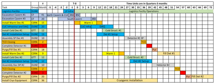
Schedule Milestones
As schedule issues arise, technical coordination will work with the affected consortium to resolve the issues. Start of FC production for detector module #1 September 2023 Start of CPA production for detector module #1 December 2023 Top of detector module #1 cryostat accessible January 2024 Start of TPC electronics installation on top of detector module #1 April 2024 Start of FEMB installation on APAs for detector module #1 August 2024. Top of detector module #2 cryostat accessible January 2025 Complete FEMB installation on APAs for detector module #1 March 2025.
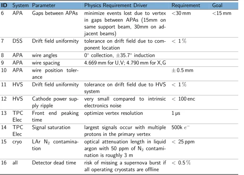
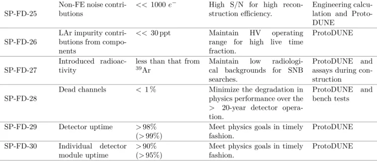
Requirements
ID System Parameter Physics Requirement Driver Requirement Objective 6 APA Gaps between APAs minimize events lost due to vertex. Volumes IV, The DUNE Remote Detector Single Phase Technology, and V, The DUNE Remote Detector Dual Phase Technology.
Full DUNE Requirements
- Single-phase
- Dual-phase
-FD-15 LAr nitrogen pollution. lt; 25 ppm Maintain 0.5 PE/MeV PDS sensitivity required to trigger proton decay near the cathode. -APA-6 Missing/unreadable channels. lt;0.5% Reconstruction efficiency ProtoDUNE-SP. gt; 500 V/cm) Reduces effects of e−-Ar recombination, e− lifetime, e− diffusion and space charge. -FD-15 LAr nitrogen pollution. lt; 3 ppm Higher pollution affects the number significantly. of photons reaching the PMT.
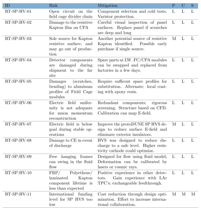
Risks
The consortia have provided preliminary versions of risk assessments collected on the technical coordination webpage (DocDB 6443 [70]). These have been developed into a general risk register that will be monitored and maintained through technical coordination in coordination with the consortia.
Full DUNE Risks
- Single-phase
- Dual-phase
RT-DP-CISC-008 Discrepancies between measured temperature map and CFD simulations in ProtoDUNE-SP.
Hazard Analysis Report (HAR)
- Construction Hazards (LBNF-DUNE HA-1)
- Natural Phenomena (LBNF-DUNE HA-2)
- Environmental Hazards (LBNF-DUNE HA-3)
- Waste Hazards (LBNF-DUNE HA-4)
- Fire Hazards (LBNF-DUNE HA-5)
- Electrical Hazards (LBNF-DUNE HA-6)
- Noise/Vibration/Thermal/Mechanical (LBNF-DUNE HA-7)
- Cryogenic/Oxygen Deficiency Hazard (LBNF-DUNE HA-8)
- Confined Space Hazards (LBNF-DUNE HA-9)
- Chemical/Hazardous Materials Hazards (LBNF-DUNE HA-11)
- Lasers & Other Non-Ionizing Radiation Hazards (LBNF-DUNE HA- 14)14)
- Material Handling Hazards (LBNF-DUNE HA-15)
- Experimental Operations (LBNF-DUNE HA-16)
Typical initiators will be transport accidents, incompatible materials, inadequate packaging or labelling, packaging failure and a natural phenomenon. Industrial hygiene hazards will be assessed, identified and mitigated as part of the risk assessment process of work planning and control. The control zone concept used in the International Building Code and National Fire Protection Association standards will be followed for hazardous chemical use and storage areas to provide the greatest flexibility and control of materials by allowing individual thresholds of inventory for the control area.
Glossary
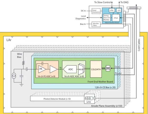
For example, the SP front-end electronics is where the cold electronics meet the sensor wires of the TPC and the front-end DAQ is where the DAQ meets the output of the electronics. Fermi Research Alliance (FRA) A joint partnership of the University of Chicago and the University Research Association (URA) that manages and operates Fermilab on behalf of the DOE. Monte Carlo (MC) Refers to a method of numerical integration that involves the statistical sampling of the integrand function.