No part of this publication may be reproduced, stored in a retrieval system, or transmitted in any form or by any means, electronic, mechanical, photocopying, recording, scanning, or otherwise, except as permitted under Sections 107 or 108 of the 1976 United States Copyright Act, without either the prior written permission of the Publisher, or authorization by payment of the applicable fee per copy to the Copyright Clearance Center, 222 Rosewood Drive, Danvers, MA fax.
Introduction
- BACKGROUND
- ELECTRICAL TRANSMISSION NETWORKS
- Automatic Generation Control (AGC)
- Excitation Control
- Transformer Tap-Changer Control
- Phase-Shifting Transformers
- FLEXIBLE AC TRANSMISSION SYSTEM (FACTS)
- Advances in Power-Electronics Switching Devices
- Principles and Applications of Semiconductor Switches
- EMERGING TRANSMISSION NETWORKS
Tap changers can be provided in one of the two windings of transformers as well as in autotransformers. Stability improvement was achieved by adding auxiliary signals to the current converter controllers [16], [17].

Reactive-Power Control in Electrical Power Transmission Systems
REACTIVE POWER
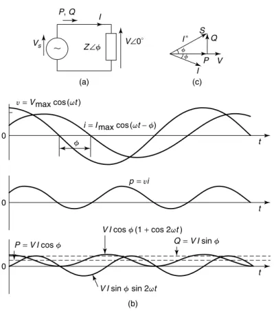
2.3) and (2.2), the peak value of the second component of the instantaneous power in Eq. 2.2) is identified as reactive power. These devices draw leading currents and result in a negative value of Q; thus they are seen as suppliers of reactive power.
UNCOMPENSATED TRANSMISSION LINES .1 A Simple Case
- Lossless Distributed Parameter Lines
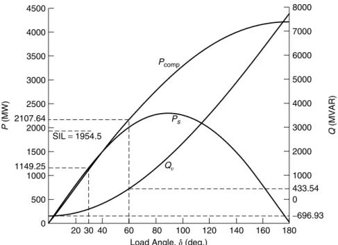
In terms of the midpoint voltage Vm, the receiving end voltage of a symmetrical line, from Vgl. In terms of the midpoint voltage, we can rewrite the power transfer of the line given by Eq.
PASSIVE COMPENSATION
- Shunt Compensation
- Series Compensation
- Effect on Power-Transfer Capacity
The result of series compensation is an improvement in the maximum power transfer capacity of the line. For the system in this figure, the power transfer is in terms of mean line voltage.
SUMMARY
Principles of Conventional
Reactive-Power Compensators
INTRODUCTION
The variation of SVC reactive-power generation as the square of terminal voltage when operating outside the linear controllable range, resulting in a significant reduction in reactive-power support at lower voltages. Although SVCs are currently widely used for reactive-power compensation, one should note that rotary synchronous condensers have been the industry workhorses for reactive compensation for decades and still find some important applications, as described in the following section.
SYNCHRONOUS CONDENSERS
- Configuration
- Applications
Synchronous capacitors are currently used for the following main applications: high voltage trip control and. dynamic support of reactive power at HVDC terminals. For example, under severe overvoltage conditions, the synchronous capacitor itself absorbs a significant amount of reactive power, even if the field current remains unchanged.

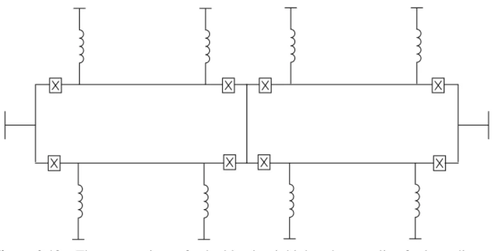
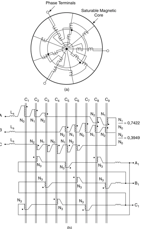
THE SATURATED REACTOR (SR) .1 Configuration
- Operating Characteristics
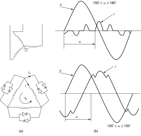
- The Single-Phase TCR
- The 3-Phase TCR
- The Thyristor-Switched Reactor (TSR)
- The Segmented TCR
- The 12-Pulse TCR
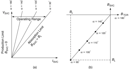
- Operating Characteristics of a TCR
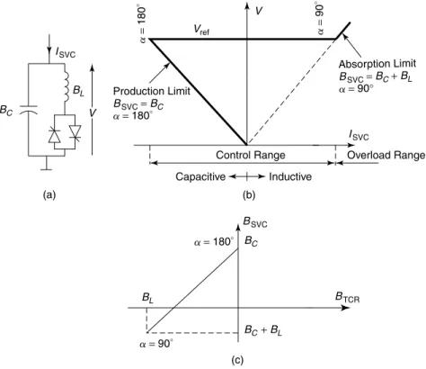
The sinusoidal current flowing in this reactor is equal to the fundamental component of the non-sinusoidal current. Note that BTCR is the sensitivity variable in the above TCR equivalent; is given by Eq. THYRISTOR CONTROLLED REACTOR (TCR) 61 SVC TCR Sensitivity Characteristics These illustrate the change in total SVC sensitivity as the TCR sensitivity changes, as shown in Fig.
These characteristics are of paramount importance for control system analysis - the controls affect the TCR firing angle, while the total susceptance BSVC affects the power system.
THE THYRISTOR-CONTROLLED TRANSFORMER (TCT)
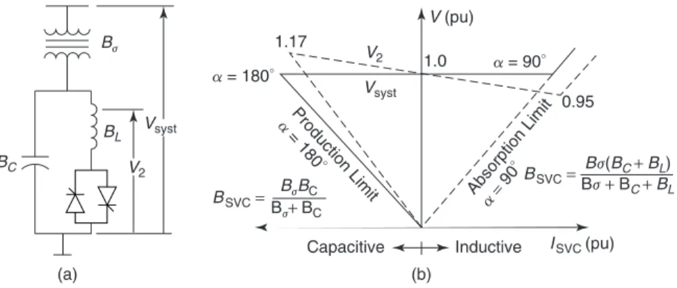
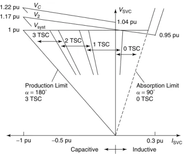
On the left, the compensator will reach the production limit if the system voltage drops excessively; the operating point will then lie on the undervoltage range characteristic. The main disadvantage of the TCT SVC is the high capital cost involved in manufacturing a special transformer. Furthermore, since no low-voltage secondary winding is available, the capacitors and filters must be installed on the high-voltage bus, necessitating a higher voltage rating of the passive components and, consequently, an increased cost.
One of the largest TCT static variable compensators is installed in the Hydro-Quebec system [15], rated at +350 MVA.
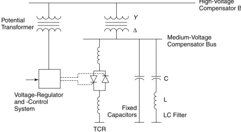
THE FIXED-CAPACITOR–THYRISTOR-CONTROLLED REACTOR (FC–TCR)
- Configuration
- Operating Characteristic
A fixed capacitor extends the control range of SVC operation to the leading side as a com- . The ISVC can be expressed as a function of the system voltage V and the total susceptance of the compensator BSVC using Eqs. The figure also shows the transformer secondary voltage as a function of the total SVC current.
Losses A drawback of the FC-TCR SVC is the high current flow in the FC-TCR loop required to cancel the capacitive vars.
THE MECHANICALLY SWITCHED CAPACITOR–THYRISTOR- CONTROLLED REACTOR (MSC–TCR)
THE THYRISTOR-CONNECTED CAPACITOR (TSC) 71 as a potential transformer, in parallel with each phase of the capacitor bank. The TCR in an MSC–TCR is designed to have a lower inductance compared to a TCR in a TSC–TCR SVC of similar rating. A lower inductance TCR produces an increased level of harmonics and therefore requires more extensive filtering than a TSC–TCR.
An MSC–TCR may not be very suitable for voltage control applications in a system that experiences frequent disturbances; nevertheless, a study [11] showed that MSC-TCRs provide performances comparable to a TSC-TCR in damping power swings between two areas and also in alleviating severe voltage suppression from system faults, all at a much lower installed capital cost than an equivalent TSC–TCR.
THE THYRISTOR-SWITCHED CAPACITOR (TSC)
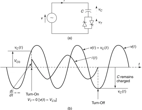
- Switching a Capacitor to a Voltage Source
- Switching a Series Connection of a Capacitor and Reactor To overcome the problems discussed in the preceding list, a small damping
- Turning-Off of the TSC Valve
- The TSC Configuration
- Operating Characteristic
Analysis of the current after closing the thyristor switch att c0 leads to the following result. However, it gives worse transients if the initial capacitor voltage is below the peak of the supply voltage (eg, VC0/V c0.75). The capacitors are charged at the peak of the supply voltage by turning on only one of the two thyristors.
The break is always at the peak of the supply voltage, where the valve voltage is minimum.
THE THYRISTOR-SWITCHED CAPACITOR–THYRISTOR- CONTROLLED REACTOR (TSC–TCR)
- Configuration
- Operating Characteristic
- Current Characteristic
- Susceptance Characteristic
- Mismatched TSC–TCR
- Losses
- Performance
Thus, a good understanding of the TSC-TCR can be obtained by applying the theory of an FC-TCR SVC developed in section 3.6 to a practical example of TSC-TCR. Small resistive losses are in the permanently connected filter branches in the TSC–TCR and MSC–TCR. The TSC-TCR losses are least in the floating state, as in MSC-TCR.
However, TSC–TCR is by far the most versatile among all SVC configurations, albeit at a high cost price.
SUMMARY
The MSC-TCR losses show a similar trend to that of the TSC-TCR, but they have a much lower magnitude in comparison, because the losses associated with the thyristor valves are absent. The selection of a specific SVC is based on several considerations - application requirements, response speed, frequency of operation, losses, capital cost, and so on. Davies, "New Synchronous Compensators for the Nelson River HVDC System - Planning Requirement and Specification," IEEE Transactions on Power Distribution, Vol.
Romegialli, "Laurentides - The First 735 kV Static Var System, Description and First Operational Results", International Symposium on Controlled Reactive Compensation, IREQ, Varennes, Quebec, 1979.
SVC Control Components and Models
INTRODUCTION
MEASUREMENT SYSTEMS
- Voltage Measurement
- The Demodulation Effect of SVC Voltage-Measurement System The SVC voltage-measurement systems have an inherent demodulation effect
- Current Measurement
- Power Measurement
- The Requirements of Measurement Systems
The output of the 3-phase measurement system depends on the phase relationship of the fundamental components of the three single-phase voltages. Should there be a 3rd harmonic component in the bus voltage, the DC output of the metering system (multiplier) will be proportional to (V21+V23) in each phase. A comparison of the Fourier analysis-based and rectification-based measurement systems is shown in Fig.
This instability can be avoided by placing band-rejection filters (ie, notches) on the AC side of the voltage converter.
THE VOLTAGE REGULATOR .1 The Basic Regulator
- The Phase-Locked Oscillator (PLO) Voltage Regulator
VOLTAGE REGULATOR 115 is simplified to the gain-time constant form of the controller shown in FIG. The voltage regulator current drop shape ensures linearity between SVC terminal voltage and current in the SVC control range. The gain KR (inverse of the current slope) is typically between 20 pu (5% slope) and 100 pu (1% slope) based on the SVC rated reactive power.
The output of this square transducer contains a DC component that is proportional to the square of the voltage (in addition to a 2nd harmonic component that is ignored by the PLO).
GATE-PULSE GENERATION
- The Linearizing Function
- Delays in the Firing System
Then, the implementation of the voltage regulator output Bref as an actual installed susceptance BSVC occurs through an intermediate stage of the firing angle calculation, as shown in Fig. In physical terms, the function F2(a) represents the firing angle calculation, corresponding to Bref, if the entire Bref is to be implemented on the TCR. For a 2-pulse TCR, the dead time is a random variable varying from 0 to T/2, where Ti is the time period of the voltage wave.
In general, for a pulsed TCR, the thyristor dead time is given by z/(2p), where is the time period of the base voltage.

THE SYNCHRONIZING SYSTEM
A very commonly used synchronization system that meets the requirements in the preceding list is based on the PLL shown in Fig. The PPL not only provides a zero-crossing signal for the fundamental voltage, but it also generates the necessary timing clock signals that are phase-locked to the fundamental frequency of the digital counters that count the firing angle. Another synchronization technique uses actual thyristor-valve voltages to generate the firing angle reference ramps to which the firing angles are synchronized [42].
However, this problem can be overcome by resorting to balancing techniques for equalizing the firing angles in the three phases and equalizing the positive and negative current pulses.
ADDITIONAL CONTROL AND PROTECTION FUNCTIONS
- The Damping of Electromechanical Oscillations
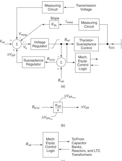
- The Susceptance (Reactive-Power) Regulator
- The Control of Neighboring Var Devices
- Undervoltage Strategies
- The Secondary-Overvoltage Limiter
- The TCR Overcurrent Limiter
- TCR Balance Control
- The Nonlinear Gain and the Gain Supervisor
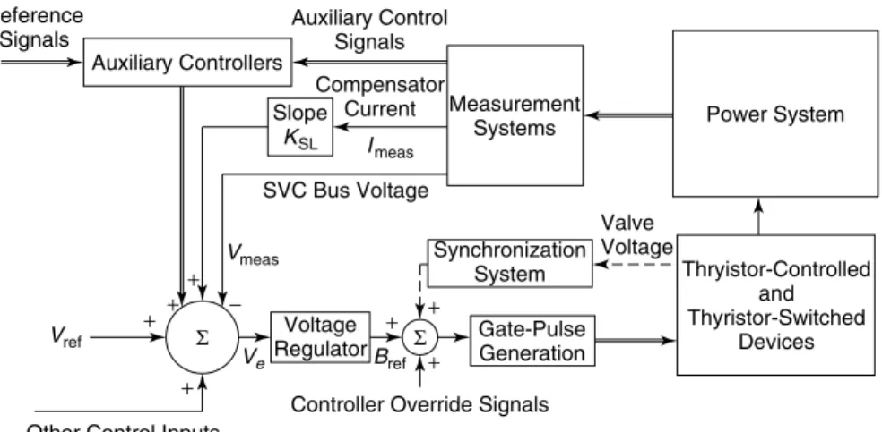
4.16(a) for IEEE Basic SVC Model 1 at the location labeled 'Other Signals'. The auxiliary control changes the voltage reference only when there is a change in the auxiliary control signal. In the event of a fault, the fast voltage regulator control uses a significant portion of the SVC's reactive power range to maintain a pre-specified terminal voltage. The Bset is usually chosen as the reactive power contribution at fundamental frequency from the permanently connected harmonic filters of the SVC.
The control function provided by the secondary surge arrester ensures that the secondary (low voltage) side of the SVC coupling transformer does not.
MODELING OF THE SVC FOR POWER-SYSTEM STUDIES
- Modeling for Load-Flow Studies
- Modeling for Small- and Large-Disturbance Studies
- Modeling for Subsynchronous Resonance (SSR) Studies In subsynchronous resonance (SSR) studies [43], a wide bandwidth of elec-
- Modeling for Electromagnetic-Transient Studies
- Modeling for Harmonic-Performance Studies
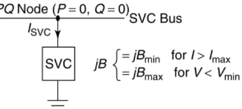
Modeling the SVC as a Q-limited PVnode is not suitable for representing the SVC under overload. In these studies, only the positive sequence behavior of the SVC-compensated system is modeled. The variable susceptance model, in which the SVC current in response to the susceptance output is given by .
The magnitudes of the nth order harmonic current, In, depend on the SVC configuration and are.
SUMMARY
Lins, “Detailed Modeling of Actual Static Variable Compensator for Electromagnetic Transient Studies,” IEEE Transactions on Power Systems, Vol. Kundur, “A Comprehensive FACTS Device Model for Power Flow and Stability Simulations,” IEEE Transactions on Power Systems, Vol. Lasseter "Equivalent circuit for the frequency response of a static variable compensator", IEEE Transactions on Power Systems, Vol.
Ainsworth, “The Phase Locked Oscillator—A New Control System for Controlled Static Converters,” IEEE Transactions on Power Apparatus and Systems, Vol.
Concepts of SVC Voltage Control
INTRODUCTION
VOLTAGE CONTROL
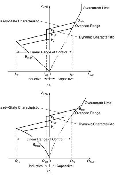
- V-I Characteristics of the SVC
- Voltage Control by the SVC
- Advantages of the Slope in the SVC Dynamic Characteristic Although the SVC is a controller for voltage regulation, that is, for maintaining
- Influence of the SVC on the System Voltage
- Design of the SVC Voltage Regulator
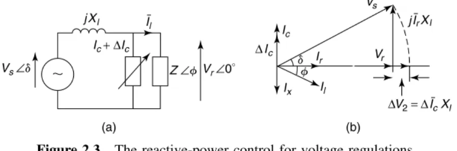
In some literature, the SVC's reactive power is defined as the sum of its inductive and capacitive rating. The voltage control operation of the SVC can be explained through a simplified block representation of the SVC and the power system, as shown in Fig. If the SVC draws a reactive current ISVC, then in the absence of the SVC voltage regulator, the SVC bus voltage is given by.
The intersection of the SVC dynamic characteristic and the system load line provides the smooth operating point of the SVC, as illustrated in Fig.
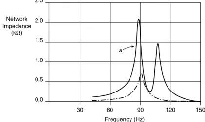
EFFECT OF NETWORK RESONANCES ON THE CONTROLLER RESPONSE
- Critical Power-System Parameters
- Sensitivity to Power-System Parameters
- Sensitivity to the TCR Operating Point
- Choice of Transient Gain
- Certain Features of the SVC Response
The stability of the SVC voltage regulator can be explained on the basis of two power system parameters: the effective short circuit ratio (ESCR) and the first resonant frequency of the AC system (Fr0) [4], [5]. The influence of power system parameters on the transient response of the SVC voltage regulator, with varying regulator gains KT [4], [5], is depicted in Fig. The SVC response generally becomes faster with the increase in trans- the gain of the voltage regulator.
They cause a small change in the voltage reference and examine the response of the voltage regulator.