Dye-sensitized solar cells (DSSCs) are one of the strong alternatives to conventional Si-based solar cells due to advantages such as transparency, various colors, and efficiency comparable to that of an amorphous Si solar cell. In the production of DSSC, the dye coating is one of the important factors in the manufacturing process. Solvents used range from mono alcohol to triols with different temperatures and dye concentrations.
Introduction
History of Dye Sensitized Solar Cells (DSSCs)
Overview of DSSCs
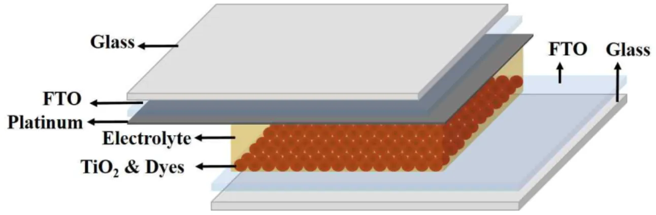
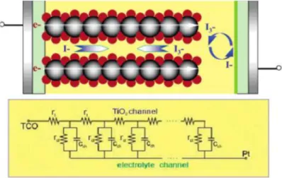
- Structur of DSSCs
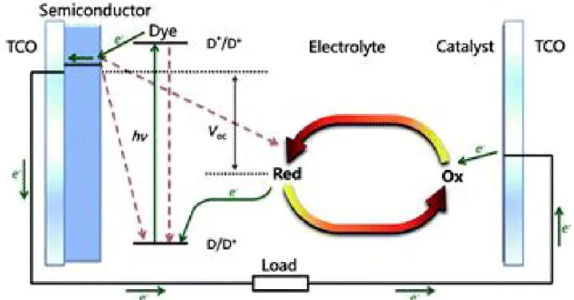
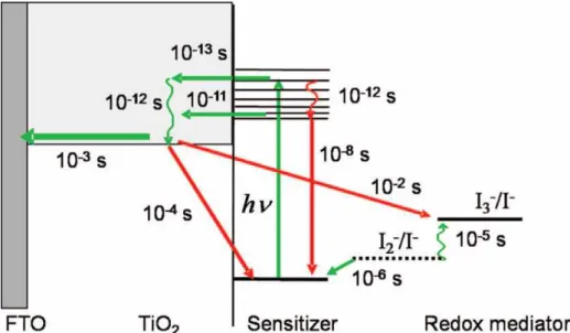
- Principles of DSSCs
- Characterization of dye-sensitized solar cells (DSSCs)
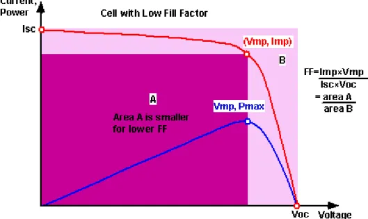
Photoexcitation of the sensitizer (S) is followed by electron injection into the conduction band of a semiconductor oxide. The positive ionic charge in the electrolyte is provided from the regeneration of the dye by electron transfer from iodide ions. The FF is defined as the ratio of the maximum power from the solar cell to the product of Voc and Isk.

Development of dye-sensitized solar cells (DSSCs)
- Reduction of dye coating time and co-adsorbants
- Low price counter electrode
Moreover, the dyes used in these systems were unstable.62 Since the initial work in the early 1990s, a myriad of DSSC components and configurations have been developed. In production, to make the manufacturing cost of DSSCs higher, dye coating is one of the important factors in the manufacturing process. Furthermore, I also present a one of the methods used to improve DSSC performance with representative Ru-based dyes such as N7, N719 is the addition of a co-adsorbing agent in the dye solution.
A novel dye coating method for N719 dye-sensitized solar cells
- Research overview
- Background and Introduction
- Experimental
- Preparation of TiO2 photo-anodes
- Fabrication of DSSCs
- Characterizations
- Result and Discussion
- Conclusion
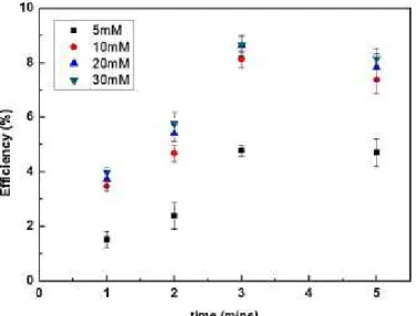
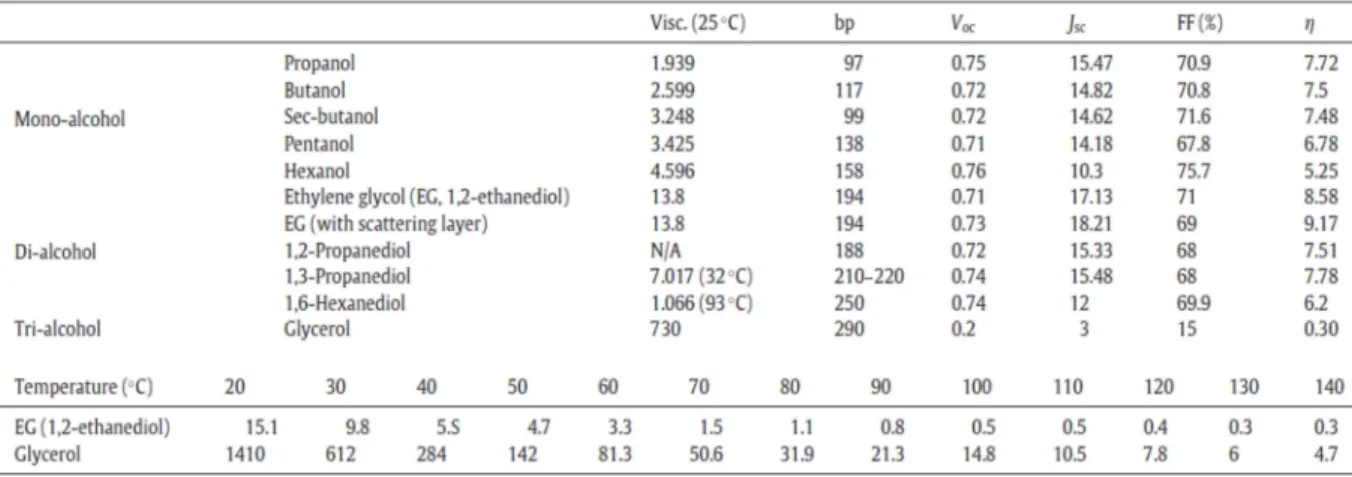
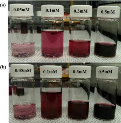
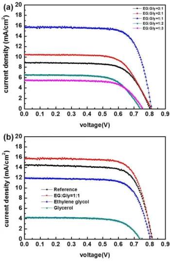
When the temperature is increased to 100 ℃, the viscosities of ethylene glycol and glycerol are decreased. First, the reaction time and the concentration of N719 dyes in ethylene glycol were investigated simultaneously. The basic solution removes all the dye molecules from the TiO2 surface, and the amount of dye can be compared with UV spectroscopy analysis.
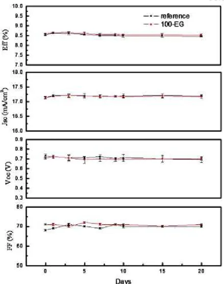
The second set and the third set from the bottom are sampled using ethylene glycol at 100℃ for 1 min and 3 min, respectively. Peaks of interest appear at 2100 cm−1, 1607 cm−1, 1541 cm−1 and 1368 cm−1, which correspond to NC(S), asymmetric vibrations of carbonyl groups (COO−), aromatic carbon double bonds , and the symmetric vibrations of carbonyl groups (COO−), respectively.88-91 When the temperature is controlled at 100 ℃, the main concern is the degradation of the dye due to oxygen and water from the environment. Since the ink molecules are surrounded by viscous ethylene glycol, they can remain protected for a short time from oxygen or water that cause color degradation.
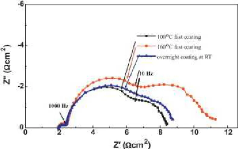
The top set was taken from the sample prepared by EG solvent for 3 min as a reference, and the other sets were prepared by EG solvent (middle) and glycerol (bottom) for 5 min, respectively. A noticeable difference was observed from the sample, the coating of which was prepared in. the second arc, which represents a resistance at the TiO2/dye/electrolyte interface. These degraded products can diffuse into the electrolyte and also affect the function of the electrolyte, and this increases the third arc (diffusion resistance in an electrolyte). 2) The main framework of N719 molecules can still be adsorbed on TiO2, and the partial ligands can be disassembled from the molecules.
Diol, especially ethylene glycol, was ideally applied to shorten the coating time to only 3 minutes, which is much improved from the several hour scale required for the conventional solvents such as acetonitrile and ethanol.
High performance dye sensitized solar cells by adding titanate co-adsorbant
Research overview
Background and Introduction
Experimental
- Preparation of TiO2 photo-anodes
- Fabrication of DSSCs
- Characterizations
The sample is masked with black opaque tape along the board of the active area.
Result and Discussion
After dye and TDT coating, the absorption peak is completely shifted as shown in Figure 3.3(b) with a drop of more than 18. The molecular conformations for a reference working electrode and TDT-assisted working electrode are compared by diffuse reflectance infrared Fourier Transform (DRIFT). The middle set in Figure 3.4 is taken from the sample using only N719 solution, and the top set is from the sample using N719+TDT.
Although not identical to each other, most of the representative peaks identifying the state of the dye appear very similar. The amount of coated dyes is compared for both electrodes by dissolving all dyes from the TiO2. According to the JV curve shown in Figure 3.5 (a) for cells prepared with a reference electrode and a N719+TDT electrode shows obvious changes.
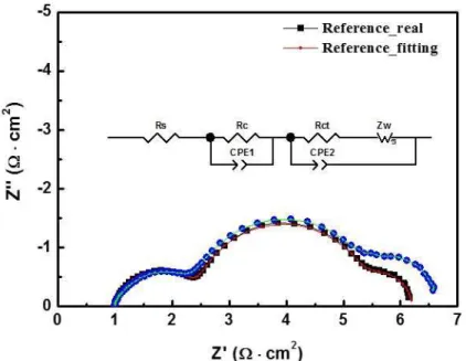
As shown in the figure, the IPCE values are higher for TDT co-adsorbed sample in all wavelengths. In Figure 3.6, EIS provides information on interfacial resistances such as a counter electrode/electrolyte interface, a dye and TiO2/electrolyte interface, and electrolyte diffusion in order from the left. As shown in the figure set, the fitting is well aligned with the real data.
The detail resistance values are summarized in Table 1. While resistances for charge transfer at the counter electrode (the first arc) are almost the same, resistances for charge transfer at dye+TiO2/electrolyte interface (the second arc)93, 95 changed from 3 Ω to 3.3 Ω.
Conclusion
We believe that the increase in current density may be due to the formation of an insulating layer with TDT than other co-adsorbents, higher sensitivity to light, and fewer dye dimers.
Research overview
Background and Introduction
The proposed dye-coating solvent system results in fast dye-coating with less dye degradation concerns even at high temperatures and is convenient for the preparation of double-layers of dye-coating on the working electrode. To successfully achieve dye coating without dye degradation, we manipulated a mixture of solvents, ethylene glycol (EG) and glycerol (Gly). In this modified system, part of the mixture delivers the dyes to the TiO2 surface, while most of the highly viscous solvent remains on top of the TiO2.
We expect that the remaining solvent, mainly Gly, on the top prevents the contact between the dyes and oxygen or moisture in the air, which mainly cause dye degradation.
Experimental
- Preparation of TiO2 photo-anodes
- Fabrication of DSSCs
- Characterizations
EIS measurements were performed in the range of Hz at 298 K using a CH Instruments electrochemical workstation (660C).
Result and Discussion
- Fast dye coating
- Application of dual dye bands on working electrodes
The EG/Gly system can benefit from a synergistic effect of both solvents relative to the individual solvents. However, the d+EG/Gly system allows samples to survive under ambient conditions for > 3 min. Electrochemical impedance spectroscopy (EIS, Figure 4.6) of the cells revealed that the EG/Gly solvent mixture affects the second arc from the left, which is related to dye-TiO2/electrolyte interface resistance.
As described above, the amount of dye molecules in the EG/Gly solvent system was lower than that of the conventionally prepared electrode. However, the new solvent system uses a highly viscous solvent, which can prevent dye aggregation as diffusion of dye molecules in the EG/Gly mixture is restricted in the Figure 4.8. The temperature of the TiO2 surface was expected to be <90℃; d+EG/Gly was cast onto the substrate and held for variable durations (on a minute scale) to obtain partially paint-coated working electrodes;.
According to the data, d+EG/Gly delivered dyes into the nanoporous TiO2 film to a depth of about 3, 7, and 9-10 mm, depending on the run time (1, 2, and 3 min, respectively). Because the temperature of d+EG/Gly was lower than that of the working electrode on a hot plate, the first minute resulted in a Ru gradient. Of course, the moving speed of d+EG/Gly may depend on the porosity of the TiO2 layer; 3–4 min was enough to deliver d+EG/Gly at the bottom of the entire layer.
Varying the EG/Gly ratio did not significantly change the depth of penetration, regardless of the amount of dye application.
Conclusion
Electrocatalytic Activity of NiO on Silicon Nanowires with a Carbon Shell and its
- Research overview
- Background and Introduction
- Experimental
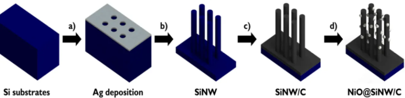
- Fabrication of SiNWs
- Fabrication of NiO@SiNW/C
- Fabrication of DSSCs
- Characterization and Measurements
- Result and Discussion
- Conclusion
NiO decoration: The NiO was decorated on the surface of the carbon shell by drop-casting method. Figures 5.2 (a)–(c) demonstrate the scanning electron microscopy (SEM) images of the NiO@SiNW/C on the Si substrate. Figures 5.4(a)–(c) show the low-magnification transmission electron microscopy (TEM) images of a single NiO@SiNW/C, and the high-resolution TEM images for the detailed nanostructures of the SiNW/C with and without the NiO decoration, respectively.
As shown in Figure 5.4 (b), the carbon shell on the SiNW surface grew along the wire axis and was randomly oriented. The XPS survey scan in Figure 5.5 (a) shows a comparison of SiNW/C with and without NiO decoration. The difference in the performance of the NiO@SiNW/C material is mainly due to the current density.
The oxidation and reduction peaks of the NiO@SiNW/C counter electrode are shifted to higher and lower potentials compared to those of the Pt counter electrode. Furthermore, the cathodic and anodic peak current densities of the NiO@SiNW/C counter electrode are larger than the current densities of the Pt counter electrode. As shown in Figure 5.8, the current density of the NiO@SiNW/C counter electrode was greater than that of the other counter electrodes.
This EIS analysis of the whole cell showed a similar trend to the dummy cells, and the Rct values for the counter electrodes coated with Pt, SiNW/C and NiO@SiNW/C.
Summary
Humphry-Baker, R.; Comte, P.; Pechy, P.; Grätzel, M., Highly efficient dye-sensitized solar cells based on carbon black counter electrodes. 27 Suzuki, K.; Yamaguchi, M.; Kumagai, M.; Yanagida, S., Application of carbon nanotubes in the electrode response of dye-sensitized solar cells. 66 Hsieh, C.-T.; Yang, B.-H.; Lin, J.-Y., One- and two-dimensional carbon nanomaterials as counter-electrodes for dye-sensitized solar cells.
73 Ramasamy, E.; Chun, J.; Lee, J., Soft-template synthesized ordered mesoporous carbon counter electrodes for dye-sensitized solar cells. M.; Comte, P.; Nazeeruddin, M.; Wang, P.; Grätzel, M., Effect of sensitizer adsorption temperature on the performance of dye-sensitized solar cells. M.; Humphry-Baker, R.; Grätzel, M., Binary ionic liquid electrolyte for achieving ≥7% power conversion efficiency in dye-sensitized solar cells.
M.; Gratzel, M., Passivation of nanocrystalline TiO2 junctions by surface adsorbed phosphinate amphiphiles enhances the photovoltaic performance of dye-sensitized solar cells. 110 Dell'Orto, E.; Raimondo, L.; Sassella, A.; Abbotto, A., Dye-sensitized solar cells: spectroscopic evaluation of dye loading on TiO2. K.; Baek, J.-B., High-performance dye-sensitized solar cells using halogenated graphene nanoplatelets as counter electrodes.
F.; Qiao, Q., Nickel incorporated nanotube/carbon nanofiber composites as counter-electrodes for dye-sensitized solar cells.
Acknowledgements