If the distance to the target is within the sensing range using this term, the target can be tracked again using the first term because the uncertainty is reduced by sensing. Finally, in the prediction step of the descending horizon method, the target can be tracked even when information about the target has not been collected.
Background and Motivation
Related Work
In the gradient-based method, to minimize the determinant or trace of the error covariance matrix in each sensor platform, the gradient of a specific metric is calculated and optimized using it. An MPC-based unified algorithm that generates the UAVs trajectory and the gimbal heading command mounted on the UAV is proposed.
Contribution of the Thesis
Peng [27] proposed the MPC-based target tracking algorithm that considers various constraints such as sensor coverage and obstacles in urban environments. [28] and [29] address the problem of cooperative target tracking, but do not consider the urban environment and communication.
Outline of the Thesis
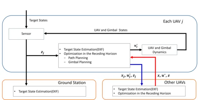
By leveraging target information from each of the UAVs, target states can be estimated. For the purpose of this thesis, we assume that the image processing, which consists of identifying each target and finding the pixel coordinates of the target's center in the image, has already been done.
Problem Formulation
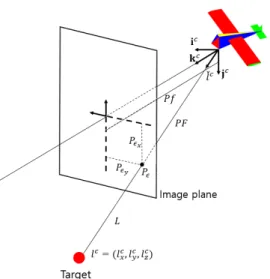
Then, the pixel location can be transformed into the corresponding bearing angle or relative unit vector by combining states of the UAV. To plan the path and gimbal for UAVs that augment target information, we first need to define the vehicle, target, sensor, and communication model.
Model Description
In this work, each UAV is equipped with a gimbal camera to estimate the position of the target. The relative position vector between the target and the UAV is expressed as l, and the position of the target in the camera frame can be expressed as follows. The coordinates of the pixel (x,y) and the dimensions of the target in the image plane can be represented as.
In this paper we used pan-tilt gimbal and the equation for the gimbal motion is given by. However, it is not easy to estimate the condition of the target using only bearing measurement.
Review of Estimation Algorithm
The Kalman filter estimates the joint distribution of the current state variables based on the current measurements. In the prediction step, the value and accuracy of the current state variable is predicted. If the initial estimate is incorrect or the process is incorrectly designed, it can quickly diverge due to the nonlinearity of the system.
However, if the system is highly nonlinear, many errors may occur in the linearization process of the nonlinear system, and the EKF may exhibit poor performance. Kalman filter is an optimal estimation technique only when the probability distribution function of the system model and observation model is Gaussian, but it cannot be used when it is not Gaussian.
EKF for Vision-based Target States Estimation
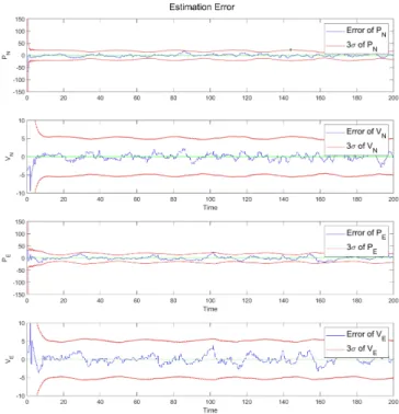
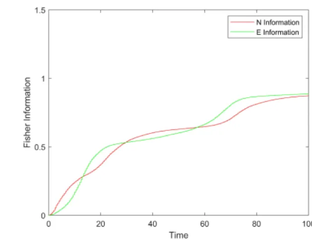
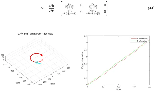
So is its Jacobian with respect to the target states. a) UAV and target position - 3D view (b) Fisher Information. The UAV flies on the target in a circular path, and apart from the initial error, it can be seen that the estimated states of the target converge to the actual position [0,0] well. Through this graph, by following the circular path and acquiring continuous information about the target, it can be seen that the information about the target's position in the N and E direction is constantly increasing.
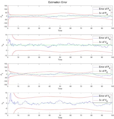
The flight path of the UAV is the same circular trajectory as in the first case. However, it can be seen that the estimation error increases compared to the first case, which is a phenomenon that occurs because the target gradually moves away from the circular trajectory of the UAV.
Estimation Quality Metric
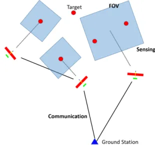
Because CRLB is formed based on the physical characteristics of the system or the geometry associated with the estimate, it provides a theoretical lower bound that any estimator can achieve. For example, if there is no target in the camera's focal plane because it is obscured by a building, αi,j becomes 0 and the target information becomes 0. The overall operation of the algorithm and the form of the target function will become short described.
In the second part, the objective function used in the proposed algorithm is formulated in detail. And in the last part, we will discuss how to examine communication with ground stations.
Overview
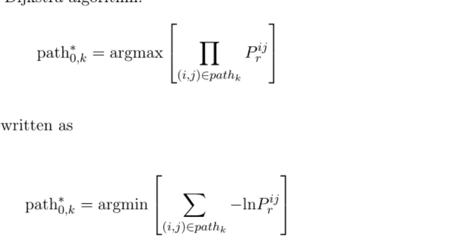
The objective function for this is proposed and the trailing horizon technique is used to maximize this. The proposed algorithm using the receding horizon technique is distributed to each UAV and for this purpose, each UAV's state information and target measurements are exchanged through a communication module between the UAVs. Second, using the clustering result, the cluster is allocated to each UAV and the weight of each cluster is calculated.
At this time, the error covariance matrix of the estimation result is used to prioritize clusters with high uncertainty, and based on that, the travel distance between the current location of the UAV and the central location of the cluster is minimized. Finally, the planning based on the receding horizon method is performed based on the status information of other UAVs and the planned input.
Objective Function
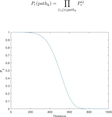
In this study, based on the information on the UAV and the dynamics of the target and the urban environment for a specific time to be predicted, the UAV roll angle and gimbal direction commands are generated to maximize the information about the target while maintaining communication with ground station. In addition, αi,jandβ0,j multiplied before the information term of each UAV are terms that consider the FOV between the UAV and the target and the communication with the ground station, respectively. In β0,j, it represents the probability of successful transmission between the ground station and each UAV obtained using the packet sweep channel model and is multiplied as a weight to reflect the communication.
In the receding horizon prediction step, the relative position of each step is calculated and the command to minimize the distance to the target is generated using this. In this case, the uncertainty of the target increases and the target can be considered by J2.
Optimization Strategy
For αi,j it is 0 if the target is outside the observation area or not in the FOV at a building, and 1 otherwise. The successful communication probability between the ground station and UAV, β0,j, is calculated, is described in detail in Section 2.2. The second term, J2, is formulated using the relative distance to the target with high uncertainty within the assigned group.
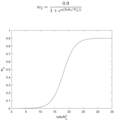
For example, if the target uncertainty remains below the threshold, w2 is kept at 0 and a command is generated that considers detection and communication without J2. However, if the target measurement cannot be obtained in the horizon distance prediction step using J1 alone, a target miss situation may occur.
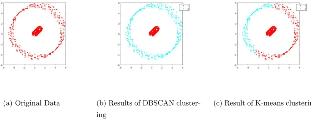
DBSCAN Clustering
Future costs are calculated over the limited time horizon stepm to ease the computational burden in each UAV. Furthermore, since the number of targets is small, the computation time is not large even when the DBSCAN algorithm is used. The objective function proposed in Section 4.2 creates a path to the target when the uncertainty of a target becomes too large.
In this case, if a target with high uncertainty is collected on one side, an inefficient path is formed because all UAVs move towards the target. To reduce this phenomenon, DBSCAN algorithm is introduced and using this clustering result each UAV is assigned and w2 is calculated.
Cluster Allocation and w 2 Calculation
The inputs of both functions are the coordinates of the center of the cluster (pc), the locations of unassigned UAVs (pnau), the number of unassigned UAVs (Nuna), and the amount of information in each cluster (Info). First, in the UAV case, a fixed-wing UAV equipped with a gimbal camera is used. Additionally, to avoid collisions, each UAV is assumed to have a different height and fly above the maximum height of the building.
In addition, it is assumed that the initial position of the target is known and that the uncertainty is large enough. Finally, since target search is not considered in this paper, it is assumed that the number and initial position of the target are known and its uncertainty is large.
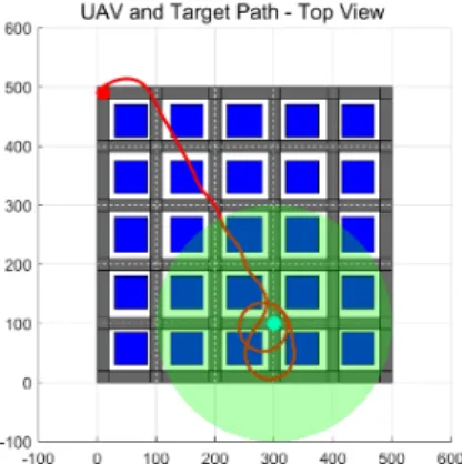
Scenario I : Effect of J 2
As shown in the graph, it can be seen that the uncertainty decreases rapidly as the UAV enters the green circle area from 18 seconds and obtains the measurement of the target. As a result, w2 quickly converges to 0, and a path for obtaining more information is created using only J1 within the green circle area where the information of the target can be obtained. The third case shows the results of numerical simulation in 70 different environments to confirm the advantages of the proposed algorithm.
The initial location of the target is randomly selected from one of 36 intersections, and each UAV is initialized at a random location near the target. Since the location of the target is completely randomly distributed, in the case of the objective function using only FIM, it can be seen that the shorter the observation range, the drastically lower the success rate.
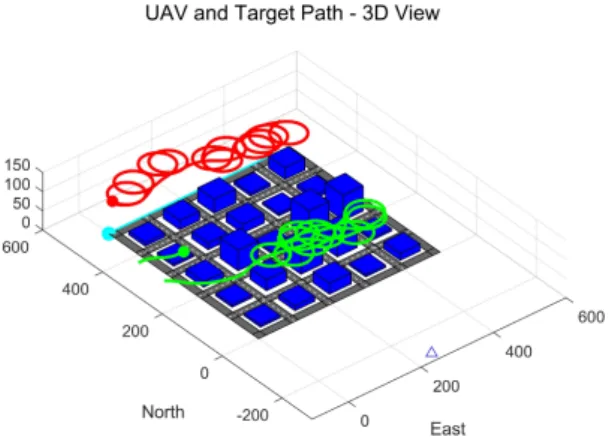
Scenario II : Communication
The ground station is also located by considering the target far from the ground station. It also shows that each UAV's trajectory is formed around the target because communication with the ground station is not taken into account. In this case, it can be confirmed that communication is not possible because the distance to the ground station is far (see Figure 18a).
Therefore, since the information about the target is not transmitted to the ground station, it can be seen that the Fisher information is not increased. Therefore, it is possible to track the target while maintaining communication between the UAVs and the ground station. Figure 20 shows the cumulative sum of the ground station Fisher information trace for each time step.
Unlike Example 1, since communication with the ground station is maintained continuously, the ground station can receive target information.