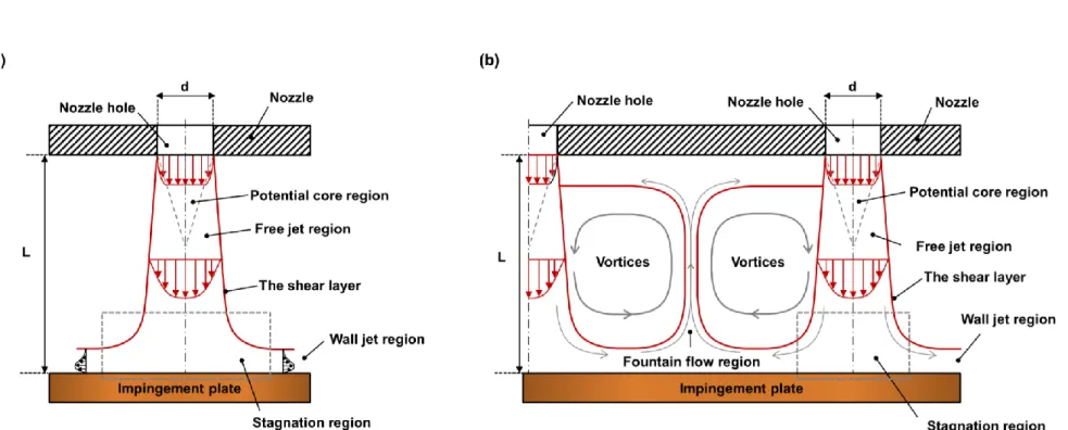
For the circular impacting jet array (CJ), the 𝑑𝑐 and S are important parameters on the 𝑇𝑎𝑣𝑒 and 𝑇𝑑𝑖𝑓, respectively. The 3D printing technique is used to build the optimal design of colliding jet arrays based on the optimization results. Schematic drawings showing the flow patterns of the impinging jet: (a) single impinging jet (b) series impinging jet ··· 5 Fig.
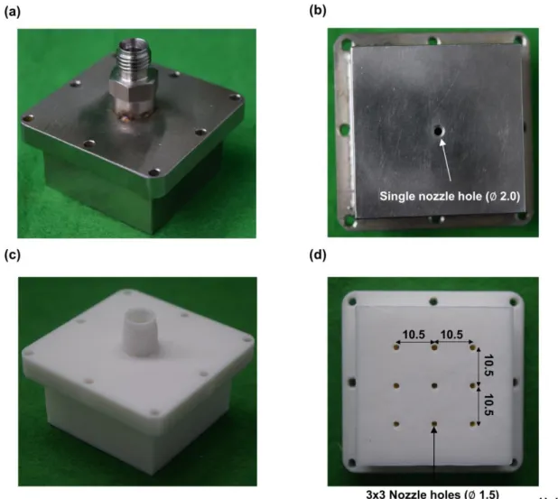
Experimental model of a nozzle with an impingement jet: (a, b) nozzle with a single impingement jet (c, d) 3D-printed nozzle with a series of impingement jets ··· 13 Fig.7. Stagnation heat transfer coefficients varying with Reynolds number: (a) CO2 shock jet array (b) N2 shock jet array ··· 18. Schematics of computational domain and boundary conditions: (a) front view (b) top view (c) CAD rendering image of shock jet array ··· 24 Fig.
Introduction
They showed that the maximum heat transfer rates appeared at L/D = 10 and that S/D is the significant factor for the incident beam. 20] described the heat transfer characteristics of impinging jet arrays, including conventional circular and elliptical nozzles. They measured the heat transfer rates and velocity profiles of colliding jet arrays for aspect ratios (AR and 2.0.
They noted that the maximum heat transfer rate can be obtained using the elliptical impinging beam due to the azimuthal curvature variations of the swirling structure.
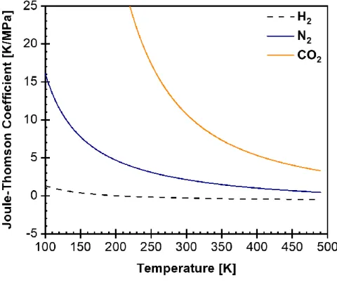
Joule-Thomson effect
Part I: Cooling characteristics of single and array impinging jets
Experimental setup and method
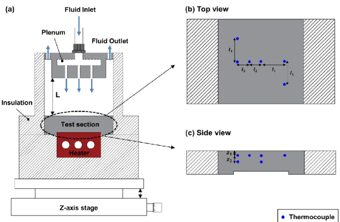
- Experimental apparatus
- FDM process of 3D printing technique
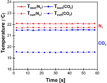
- Measurement procedure
The insulation material is installed around the heater, test section and impinging beam array to prevent the heat losses to the environment. The nozzle-to-plate distance (L) is controlled by a z-axis stage installed below the impinging jet cooling system. For the experiment validating numerical optimization results, the incident jet arrays are produced by the 3D printing technique.
Therefore, 3D printing technique is used in this study to build complex geometries for impinging beam experiment. The problem is that structures are undersized as CAD design modeling due to thermal contraction and expansion of the 3D printing material when heated and cooled. It is therefore necessary to develop the correlations between the 3D printed structure and CAD design modeling.
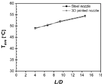
The printing speed is 50 mm/s and it takes about 27 hours to 3D print the impinging jet array. It has been confirmed that the nose of the 3D printed array consisting of white PLA matches well with the CAD design, as shown in Fig. Therefore, it is confirmed that the jet heat transfer collision results using the 3D printed jet array are reliable.
The initial circular impinging jet array (ICJ) is set as the reference configuration for the optimization study. Experimental model of colliding jet nozzle: (a, b) single colliding jet nozzle (c, d) 3D printed colliding jet nozzle.
Results and discussion
- Effect of expansion
- Effect of L/D
- Effect of 𝑅𝑒 𝐷
- Temperature non-uniformity
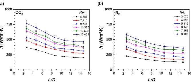
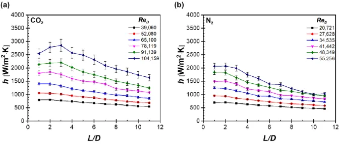
In previous study, the heat transfer characteristics of the single incident jet with varying L/D and 𝑅𝑒𝐷 by San et al. 10 shows the heat transfer coefficient with varying L/D for array impinging jets using CO2 and N2 jet. Compared to the single impinging jet, the stagnation heat transfer coefficient of array impinging jets decreases linearly as L/D increases.
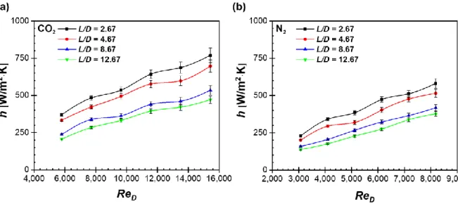
Therefore, the high 𝑅𝑒𝐷 increases the heat transfer coefficient, both cases of CO2 and N2 incident beam. 11(a) and (b), the heat transfer coefficient of a single CO2 incident jet is more sensitive to 𝑅𝑒𝐷 rise than N2. Like the single jet, the high 𝑅𝑒𝐷 and low L/D guarantee the improved heat transfer coefficient.
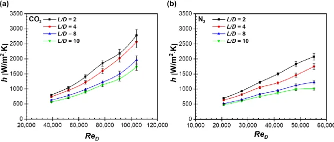
The heat transfer coefficient of the incident beam increases faster at the high 𝑅𝑒𝐷 than at the low 𝑅𝑒𝐷. Figure 13 shows a comparison of the stagnation heat transfer coefficient between single and array colliding jet with different Ν𝑒𝐷 and volume flow rate at L/D= 2.0. For the condition of the same 𝑅𝑒𝐷, the stagnation heat transfer coefficient of the impinging N2 beam is higher than that of the incoming CO2 beam, as shown in Figure 2.
The heat transfer coefficient for a single N2 beam from 𝑅𝑒𝐷= 55.256 is almost twice that of a single CO2 incident beam from 𝑅𝑒𝐷= 52.079. The stagnation heat transfer coefficient of the single impinging jet is always higher than that of the array impinging jet due to concentrated flow velocities to the stagnation point.
Part II: Geometry optimization and confirmation experiments
Computational details
- Governing equations
- Turbulence and near-wall modeling
- Computational domain and boundary conditions
- Grid independence test
The flow region of the incident jet lies in the fully turbulent flow, so the realizable k-ε turbulence model is adapted in this study. As a result, the realizable k-ε turbulence model accurately predicts the jet dispersion and near-wall turbulence effects than the standard k-ε turbulence model [ 48 – 50 ]. One of the most important considerations for the numerical study of jet impingement heat transfer is in the vicinity of the impinging surface, especially the near-wall viscosity affected layer.
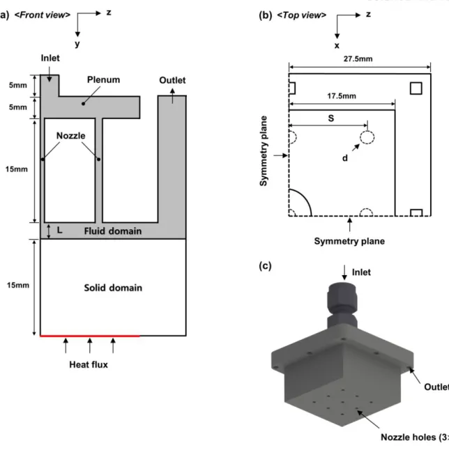
In the EWT for momentum and energy equations, the law of the wall is formulated to extend its applicability throughout the near-wall region by mixing the linear (laminar) and logarithmic (turbulent) using a. The temperature and velocity of the near-wall region are obtained by mixing the laminar linear substrate and turbulence logarithmic laws. The schematic drawings of the computational domain and boundary conditions for the simulation of array-impacting jet cooling are shown in Fig.
The structure of the outlet is replaced as the square based on the same hydrodynamic diameter to facilitate the net generation. Although the numerical simulations are performed for a small part of the domain, symmetry planes facilitated the calculation, which takes into account the 3×3 array nozzle holes. Schematic of the computational domain and boundary conditions: (a) front view (b) top view (c) CAD rendering image of impinging jet array.
Due to the enormous temperature gradients and thermophysical properties near the impacting wall, much finer grids are needed near the impact surface to resolve the near-wall region with EWT. To ensure accurate predictions of the area near the wall, the dimensionless distance to the wall (𝑦+) is kept less than unity in this study.
Optimization strategy
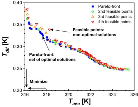
The optimization study aims to find the optimal geometry of jet array that satisfies the objective function which minimizes the average temperature (𝑇𝑎𝑣𝑒) and maximum temperature difference (𝑇𝑑𝑖𝑓) of the target surface. The optimization process is divided into three steps, design of experiment (DoE), response surface methodology (RSM) and optimization. The response surfaces are built based on the CFD simulation results of DoE points using the Kriging model.
The Kriging model is an interpolation technique and has several advantages over other interpolation methods. As such, the Kriging model is suitable for CFD calculation which has a high nonlinearity strength. If the quality of the response surface is poor, the optimization process returns to the first step and increases the number of DoE points and then builds the response surface again until the quality meets the criteria.
The last step is the optimization of the design parameters using the multi-objective genetic algorithm (MOGA). MOGA is a modification algorithm of the genetic algorithm (GA) based on the law of survival of the fittest to find multiple non-dominated solutions in a single run [55]. MOGA is based on the Non-Dominated Sorted Genetic Algorithm-II (NSGA-II), which uses the concept of elitism to find the Pareto front, which is classified as non-dominated solutions.
To verify the candidate optimization result, the CFD calculation (real solve) is performed. If the difference between the CFD calculation and the candidate optimization result is less than 5%, select the candidate optimal solution and return to the first step, DoE, if it exceeds 5.
Results and discussion
- Optimization results
- Response surfaces
- Sensitivity analysis
- Effect of S/D
- Comparison of flow characteristics
- Confirmation experiments
22(e) – (h), 𝑇𝑑𝑖𝑓 decreases with increasing nozzle size, which tends to be the inverse of 𝑇𝑎𝑣𝑒. Also, it is confirmed that the uniform elliptic jet cooling performance is achieved with increasing S. Once the jet is released from the nozzles, it undergoes flow separation and enlargement due to entrainment of the surrounding fluid. At small S/D, jet-to-jet interaction occurs before the jet hits the target surface, this phenomenon is called jet interference.
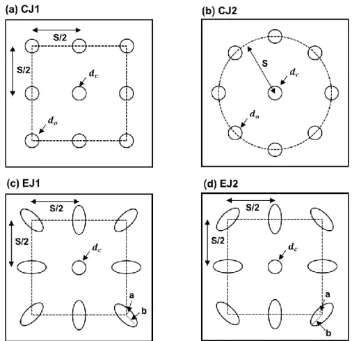
Jet interference disrupts the flow motions of the jets, therefore impairing the cooling efficiency of the jet array. 26 (a) and (b), the axial velocity distributions at the center of the jet do not differ significantly between CJ and EJ, but a noticeable difference appeared in the jet interaction region. The axial velocity and TKE profiles of configurations CJ1, CJ2, EJ1, and EJ2 in the jet center and interaction region are compared in Fig. 1 .
The location of the beam interaction region is chosen based on the value of half the beam-to-beam spacing. 27(a) and (b), the axial velocity curves for all optimum array jet designs have similar distributions, which means that the axial velocity profiles at the jet center are independent of nozzle geometry. However, there is great difference between the optimum configurations in the axial velocity of the jet interaction region, the highest axial velocity distributions are obtained for EJ2.
In the center of the jet, the TKE profiles of the circular array of jets (CJ1 and CJ2) are slightly lower than those of the elliptical array of jets (EJ1 and EJ2). The TKE curves in the jet interaction region have a similar trend for all optimal designs, but the TKE strength varies significantly. In a series of impinging jets, vortex rings form due to jet interaction between adjacent jets.
The optimal designs for EJ1 and EJ2 have a circular nozzle in the center of the jet array and elliptical nozzles on the outside of the jet array with the inline arrangement.
Conclusions
Part I: Cooling characteristics of single and array impinging jets
Chang, “Heat transfer of an impinging jet array over a concave dimpled surface with applications to cooling electronic chip sets,” Exp. Lochegnies, "Heat transfer and flow characteristics of the cooling system of an industrial glass tempering unit", Appl. Leng, “Experimental and numerical investigation of heat transfer in an array of impinging jets on a concave surface,” Appl.
Chen, “Effects of jet-to-jet separation and jet height on the heat transfer characteristics of a colliding jet array,” Int. Weigand, "Experimental and Numerical Investigation of the Heat Transfer Characteristics of Inline and Stacked Arrays of Impingement Jets", J. Nuntadus, "Correlation of Impingement Jet Array Heat Transfer from a Tube Nose Under Fully Developed Flow", The application.
Specht, “Influence of nozzle shape on heat transfer uniformity for in-line series of impinging air jets,” Appl. Lee, “The Effect of Nozzle Aspect Ratio on the Heat Transfer Characteristics of the Stagnation Region of Elliptical Impinging Jet,” Int. Prabhu, “Influence of nozzle shape on local heat transfer distribution between smooth flat surface and impinging air jet,” Int.
Ipek, “Investigation of flow structure and heat transfer characteristics in a variety of impinging slot jets,” Heat Mass Transf., vol. Prabhu, “Influence of jet temperature and nozzle shape on the heat transfer distribution between a smooth plate and incident air jets,” Int.
Part II: Geometry optimization and confirmation experiments