울산대학교 대학원 기계공학과 항공우주공학전공. 울산대학교 대학원 기계공학과 항공우주공학전공.
INTRODUCTION
Overview
Both the camera and the laser generator have some noise in their outputs, and like all non-contact 3D measurement sensors they are highly dependent on the target object's material, color, etc., and we found that noise in the laser lines and miscalculations of the system calibration greatly affect the final results , especially in a noisy industrial environment. The proposed method is implemented in three steps: adaptive detection of laser strips; accurate calibration of the measuring system using a square and finally intelligent 3D measurement.
Research objectives
In this work, a high-speed precision non-contact 3D measurement structure using a combination of CMOS camera and laser is studied. Accuracy, robustness, and speed are requirements common to most applications, not only in industrial settings, making the proposed procedure useful in many other types of applications.
Dissertation outline
FUNDAMENTAL TECHNIQUES IN MONOCULAR VISION SYSTEMS
- Introduction
- Camera calibration
- Extrinsic calibration of camera and structured light by using a rectangle
- Camera and rectangle object calibration
- Extrinsic calibration of the structured multi-line light laser and calibration plane
- Experimental results
- Computer simulations
- Real data
- Chapter summary
Checkerboard Kimages provides a 2NK constraint (multiplied by 2 because each point in the image has an x and y coordinate). The external parameters of the multiline laser light and the calibration plane can be calculated as follows:.
CIRCULAR OBJECT DETECTION AND TRACKING USING DYNAMIC
Introduction
Advanced methods such as detection using Eigen-space matching techniques [54], convolution of images with feature detectors [55] or the recent method based on sparse coding [56-58] in which static images and acquired images are represented by sparse coding and the target is tracked by the sparse coding comparison is too computationally complex and thus far too expensive for a real-time system. Our goal in this paper is to find a simple, fast tracker for real-time systems that works with inexpensive cameras and does not require calibrated lenses. The main contributions of this work include proposing a new method for robust circular object detection based on feature fusion, which can be performed at a frame rate of 30 Hz.
Circular object detection and tracking
- Feature Space
- Feature Estimator
- Fusion of color and shape for irregular moving object detection and tracking . 33
- Installation and reinstallation after occlusion confirmation
- Performance of chasing a moving target
- Performance of object detection
- Performance w.r.t the changing of illumination
- Performance w.r.t the changing of view point
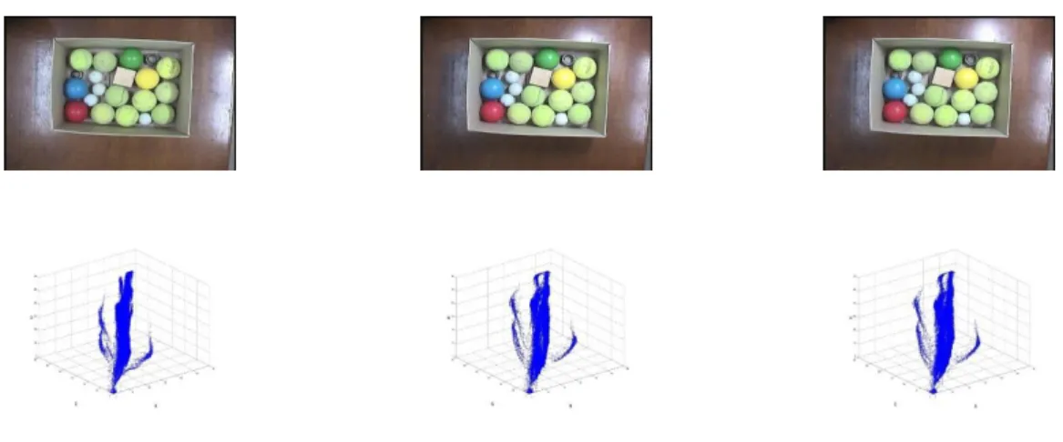
In this paper, we take the 1D histogram from the H (hue) channel in the HSV space. A circle candidate set is first created from the contour segments, ST, and then the circles actually represented in the image are defined. After the virtual circles are generated, the next step is to validate whether the circles really exist in the image.
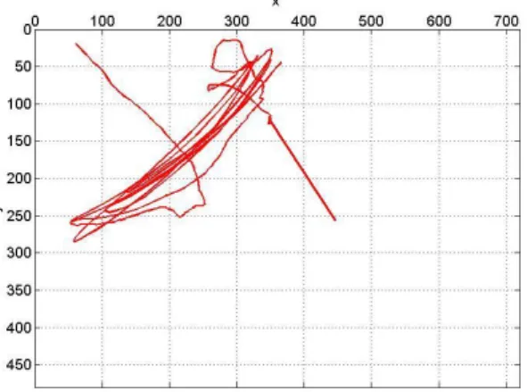
In the experiment, we assume that the target object moves slowly, less than the maximum speed of the camera.
Chapter summary
3-9Video sequence contains viewpoint changes. a) Initialize model; (b) Tracking using online feature fusion; (c) Tracking with shape information only fails due to viewpoint changes. Using shape features alone is not enough to accurately track the target, as can be seen in Fig. However, the amalgamation of features still successfully follows the target, as shown in Fig.
Overall, the online fusion of color and shape provides a robust approach to object tracking.
SLIPPAGE MEASUREMENT USING MONOCULAR STRUCTURED LINE
- Introduction
- Related works
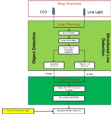
- Proposed system overview
- Slippage measurement
- Target object pose estimation
- Slippage measurement
- Experimental results
- Target object increment distance measurement
- Slippage estimation with different target objects
- Chapter summary
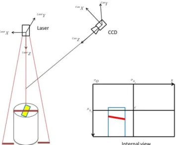
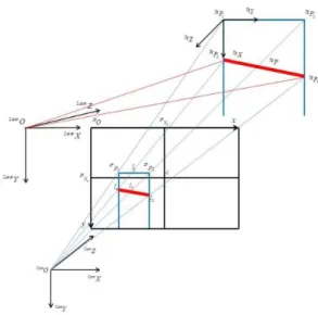
Due to noise, change of lighting, perspective, etc., the rectangular feature does not always appear as a rectangle and the rectangle is divided into two areas by the textured line light. The uncooperative pose of the target object is determined based on the information from the structured light line and the partial rectangle function. The target object can now be reconstructed in the camera coordinate system with the information from the vertices CamP1,CamP2.
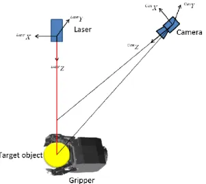
In a real environment, due to the huge size of the target object, the limitations of the camera's field of view, the gripper, etc. the camera cannot capture the entire object.
GAP AND FLUSH MEASUREMENT USING MONOCULAR STRUCTURED
Introduction
Then the laser stripes are mapped into the 3D world coordinate for gap and flush estimation, using our proposed gap and flush measurement approach. The proposed clearance and flatness measurement system can handle complex surfaces with high accuracy, meeting the demanding requirements for clearance and flatness measurement in vehicle assembly. New image processing algorithms are proposed for adaptive laser stripe extraction and classification by automatically selecting a laser profile area and improving the intensity difference between the laser area and the background.
Suggest gap and clearance measurement methods for simple objects as well as complex objects, especially gap and clearance measurement methods used in vehicle assembly.
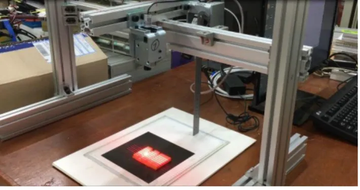
Gap and flush measurement system
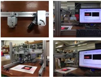
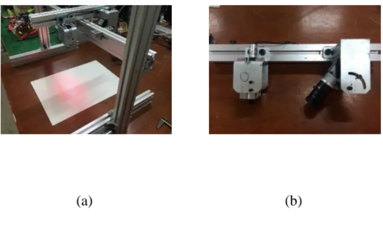
During the measurement process, the multi-line laser of each module projects laser strips onto the surface of the measured object, parts of the car body, and the camera captures the strips formed at the intersections of the laser planes with the target surface. The image processing module of the gap and plane measurement software installed on the computer analyzes the deformation of the gap and plane measurement laser strips. Finally, the measurement software GUI displays the measured gap and alignment values.
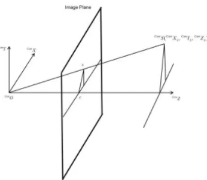
The origin IPOof IP is at the top left of the image plane and the center of the image plane is IPc=[IPxc,IPyc,1]T.
Image Processing Module
- Selection of the ROI
- Laser stripe detection and classification
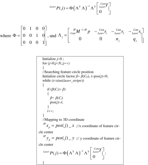
- Feature circle extraction
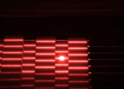
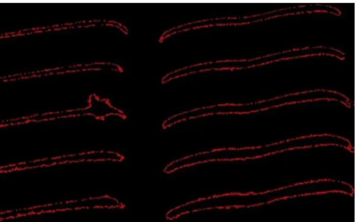
First, the laser peaks are detected, usually by considering each row or column of the image as independent signals. Considering only each image row or image column for laser detection [28] has a significant drawback. In order to reduce the computational time and at the same time achieve high accuracy of laser stripe detection, we developed an efficient method for laser stripe extraction in the obtained ROI image.
Therefore, we propose an approach to classify laser lines by segmenting the image into different parts in which the laser lines are deformed by the gap and spilled onto the surface of the object.
Proposed gap and flush measurement method
Our next step is to map the feature circle center one way, the feature point another way, into a 3D coordinate system, which is a laser coordinate system. Using the information in the calibration step, we can express the estimated curve function in the laser coordinate system. The physical transformation between the laser projector's coordinate system and the camera's coordinate system is the sum of the effects of a rotation CamLaserR and a translation CamLaserT, which were precisely calculated in the camera and laser calibration process.
Laser =LaserT LaserT= Laser Laser Laser Laser (5-5) The relationship between camera coordinate system and laser coordinate system can be illustrated by.
Experimental results
- Camera-laser module performance confirmation
- Gap and flush measurement in real vehicle assembly
This experiment is performed for different gap and coil values to investigate the proposed camera laser module measurement performance. The proposed camera-laser module projects the laser lines on the measurement positions and measures the gap G and coil F. First, the measured gap G and coil F are compared with the ground truth values gap G and coil F to determine the proposed camera-laser module's measurement accuracy.
Second, the measured gap G and flush F are compared with the means of the Gand flush F measurement values to examine the proposed measurement accuracy of the camera-laser module.
Chapter summary
Thi-Trang Tran, Cheolkeun Ha, “Non-Contact Gap and Flush Measurement Using Monocular Structured Light Vision,” at the 16th International Conference on Control, Automation, and Systems, HICO, Gyeongju, Korea, 2016. Tran Thi Trang, Cheolkeun Ha, “ Irregular Moving Object Detecting and Tracking Based on Color and Shape in Real-time System,” In 2013 International Conference on Computing, Management and Telecommunications (ComManTel), Ho Chi Minh, Vietnam, 2013. Kittler, “The adaptive Hough transform,” IEEE Transactions on Pattern Recognition and Machine Intelligence 9, p.
A FIR filter approach”, I: Pattern Recognition, Proceedings of the 17th International Conference on ICPR 2004, vol.
MONOCULAR STRUCTURED LIGHT VISION-BASED SURFACE
Introduction
In both hypothetical scenarios, there is a desire to implement UAV without prior knowledge of the surface's information using onboard sensing. The proposed system is also different from other laser camera-based vision systems that use laser beams that may appear similar at first glance. This problem is avoided in the proposed system by using automatic laser region extraction and laser profile classification.
In addition, the modest hardware design in the proposed system; there is only single camera and laser generator.
Laser profile extraction
The laser beam based systems usually use laser spots and simple brightness detection to find laser projection on the surface. Usually, in multi-line laser generator, they use color coded to classify the laser lines. Therefore, we proposed an approach to classify the laser streaks by segmenting the image into different parts where the laser lines are deformed by the gap and level on the object surface in industrial environment.
First, we group the detected curves into 2 sets deformed by the gap and flush.
Proposed ground surface estimation
Each set contains curves, where is equal to Nc and Nc is the number of lines generated by the multi-laser line generator. By solving equations (5), (6) and (7), the laser coordinate of the laser point LaserP can be calculated as follows. Thus, p has np rows corresponding to each user-entered data point and nx ny· columns.
At each point of the plot, the interpolation algorithm will try to make the same partial derivatives of the plot in neighboring cells.
Experiment Results
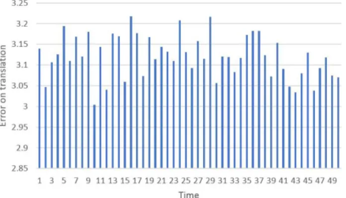
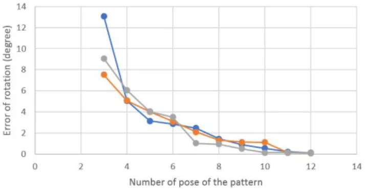
This experiment is conducted to measure different angles to study the angle estimation performance of the proposed vision system. The proposed system projects laser lines onto a flat surface and estimates the angle between the plane and the horizontal. The proposed camera-laser module projects laser lines onto the measuring positions and measures the spacing.
In order to verify the accuracy and precision of the proposed measurement of the camera-laser module, a gap and alignment measurement test is performed independently at each position 30 times.
Chapter summary
CONCLUSION
Tran Thi Trang, Cheolkeun Ha, “An efficient approach for circular shape target recovery,” In 2015 IEEE International Conference on Advanced Intelligent Mechatronics (AIM), Busan, Korea, 2015. Malik, “Geometric blur for template matching,” IEEE Conference on Computer vision and pattern recognition (Vol. Muñoz, “Image Classification Using Random Forests and Ferns,” IEEE International Conference on Computer Vision, Rio de Janeiro, October 2007.
59] Tran Thi Trang, CheolKeun Ha, "Irregular moving object detecting and tracking in real-time system," International Conference on Management and Telecomunications (Com-ManTel 2013), Hochiminh city, Vietnam.