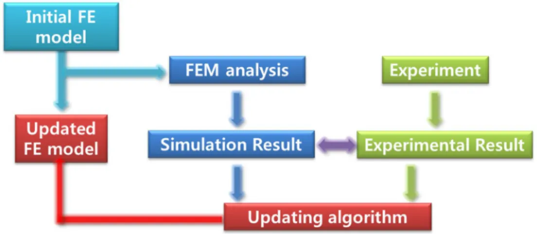
In the existing FE model updating method, generally the translational responses measured by accelerometers were used to identify the structural properties and update the control parameter of the numerical model. This paper proposes an FE model updating method that uses only the rotational response, such as angular velocity measurement, because the rotational response is more sensitive to damage than the translational response in numerical analysis on a simply supported beam. The FE model update is performed for the numerical simply supported beam using an optimization algorithm that minimizes the gap between the actual structure responses and the FE model reduction.
The responses used in FE model update are natural frequencies and rotational mode shape obtained from angular velocities measured by gyroscope sensor. Then, the updated model using existing translational response from the experiment, two FE models updated using translational and rotational responses are compared to validate the improvement by the proposed FE model updating method. From the experiment, using rotational responses is a good enough in FE model update compared to existing method using translational responses.
INTRODUCTION
For example, [6] shows the change of natural frequency and mode shape of the Bernoulli-Euler beam after crack growth. 8] is the research of updating FE model using natural frequency, damping ratio and mode shape measured by FBG acceleration and strain sensors. 6-8] and most of the existing research adopted only translational responses to estimate the natural frequency and mode shape.
According to the result of [6], the change of mode shape due to crack growth is small. Therefore, at both ends, the translational mode shape is the minimum and the rotational mode shape is the maximum. In other words, because the rotational mode shape change is expected to be more sensitive than the translational mode shape change to the non-continuous state of a beam such as crack or damage, it is also expected that the use of the shape of rotation mode when updating FE models will be more effective.
BACKGROUNDS
The mode shape from the translational DOF is a sine function based on the sine function, while the modes are formed from the rotational DOF based on the cosine function. Since the mode shape is not a value but a shape, the MAC value was adopted to compare the mode shape when updating the FE model. The modal assurance criterion, MAC, is an index for the correlation between mode shape vectors introduced by Allemang and Brown [11].
Close to 1 of MAC means that the state shape vectors have high similarity and close to 0 of MAC means that the state shape vector has no similarity. In FE model update, the MAC value used to compare state shape will be updated close to 1. 6) The MAC value used in FEMU is used to compare the state shape from the finite element method of the initial model or update model and state form of experimental result. It indicates the criterion for modal safety, which is covered in the previous chapter 2.2, between the i-th mode from the real structure and the FE model.
PRELIMINARIES
Modeling for Numerical Analysis & System Identification of Model
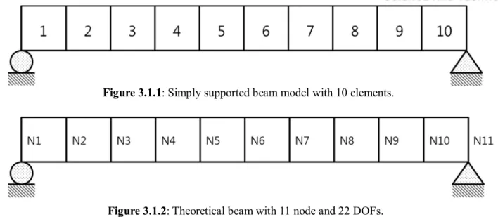
A simply supported beam of length 2 m under the assumptions of Euler-Bernoulli beam theory is modeled in MATLAB as shown in Figure 3.1.1. Since each node has 2 degrees of freedom due to translational and rotational displacement, the beam has 11 translational DOFs and 11 rotational DOFs. Note that since the vertical displacement at the boundary node is 0, the translational response at the first and last nodes is zero.
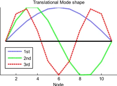
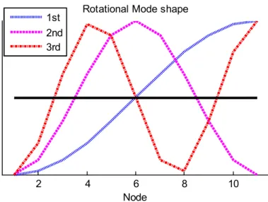
To analyze the modal properties of translational response and rotational response, the eigenfrequencies and mode shapes are obtained by solving the eigenvalue problem. The first three mode shapes with respect to the translational response are shown in Figure 3.2.1, and the first three mode shapes with respect to the rotational response are shown in Figure 3.2.2. The resulting shape of the 1st translational mode is half of a sine function and the resulting shape of the 1st rotational mode is half of a cosine function, as in theory.
By calculating modal characteristics, the system identification is performed, and using these natural frequencies and mode shapes of the baseline, the next step, the sensitivity analysis, will be performed.
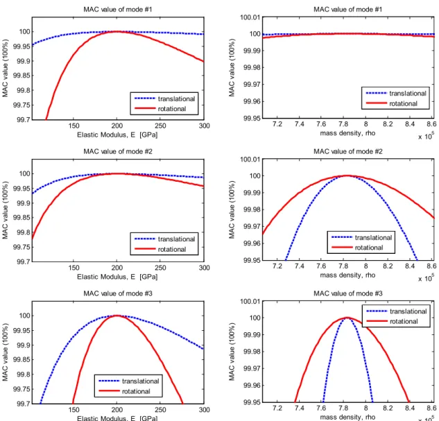
Sensitivity Analysis of Translational and Rotational Mode Shapes Using MAC value
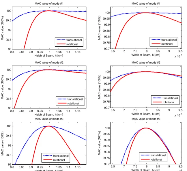
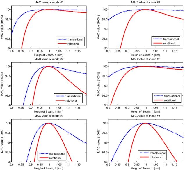
But from the following modes, the change of MAC value from rotational mode shape is less sensitive than the change of MAC value from translational mode shape than change of mass density. The difference of MAC sensitivity in 1st mode is much smaller than the difference of MAC sensitivity in following modes. The sensitivity analysis for height of section is performed by controlling the height of the 6th elements on the modeled beam whose original height is 10 cm and the result with in first three modes is shown in figure 3.3.2.
The change of the MAC value with respect to the shape in the rotation mode is more sensitive than the change of the MAC value of the shape in the translation mode as a change in the height of the beam. Furthermore, as the height of the sixth element decreases, the MAC value decreases more drastically. The sensitivity analysis for the width of the section is performed by checking the width of the sixth element on the modeled beam, whose original height is 8 cm. The result in the first three modes is shown in Figure 3.3.2.
Since the moment of the 2nd section is calculated by multiplying the width and the cube of the height, the height is a more sensitive parameter than the width to the MAC value. The change in the MAC value from the rotational mode shape is more sensitive than the change in the MAC value from the translational mode shape than the change in the beamwidth. Furthermore, as the width of the 6th elements decreases, the MAC value decreases more drastically.
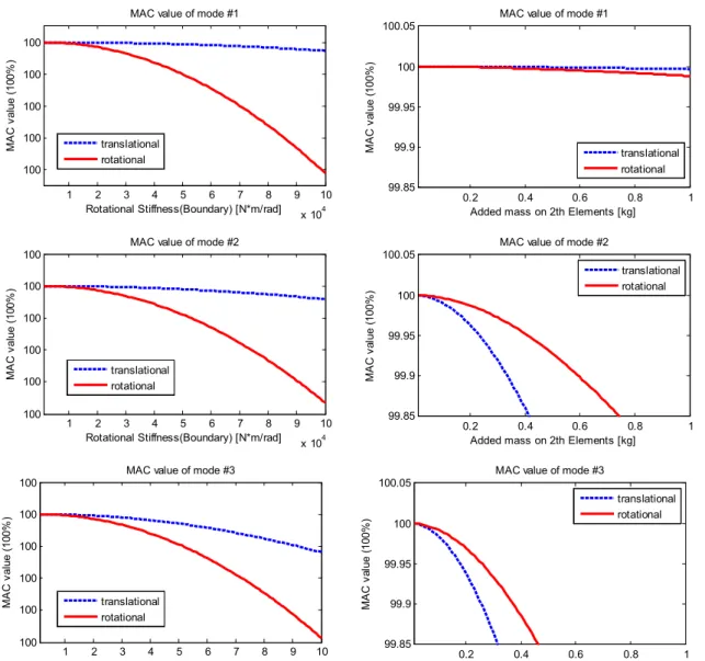
The change of the MAC value from the rotational mode shape is more sensitive than the change of the MAC value of the translation mode shape as the increase of the rotational stiffness of both boundaries. The sensitivity analysis to add mass is performed by adding mass on the 6th elements on the modeled beam and the result with in the first three states is shown in Figure 3.3.3. Only in 1st mode, the change of MAC value from rotational mode shape is more sensitive than the change of MAC value of translational mode shape as the mass added on 6th elements.
But from the following modes, the change of MAC value from rotational mode shape is less sensitive than the change of MAC value from translational mode shape as the mass added on 6th elements.
FE Model Updating Process Approached by Using Rotational Response
NUMERICAL SIMULATION
- Selecting Parameter
- Numerical Simulation using Exact Values
- Numerical Simulation using Excitation
- Validation of FE Model Updating using Rotational Response
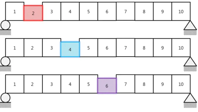
Figure 4.1 compares the MAC sensitivity of 2 damage cases – damaged on the 2nd element and damaged on the 4th element. The FE model updating process using the exact value found by the theoretical model is performed to determine the locations of damage. As shown in Figure 4.2, the reduced height of the 2nd element, the 4th element and the 6th element is always assumed.
For each case, the FE model update is performed twice using the theoretical frequencies and mode shape. As a sensitivity analysis, using rotational responses in model updating is more efficient than using translational responses at all locations analyzed. The size of the damage is also related to the success of the model update, because the simplex method is particularly dependent on the starting point.
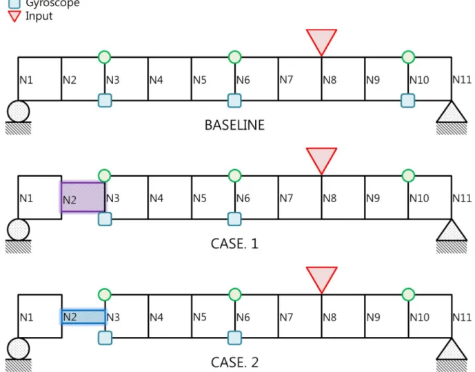
Rotation mode-based FE model update is dominant to detect damage near the end of beam. Because the purpose of this research is to verify the possibility of using rotational response in FEMU, the FE model update using rotational response will be performed and compared with the translational response for the three cases as below table 4.2. To avoid symmetrical sensor placement, the distance between sensors is different, e.g. the distance between 1st location and 2nd location is 40cm but the distance between 2nd location and 3rd location is 60cm.
To achieve the purpose of this study, the performance of updating FE models using rotational response from simulation response is evaluated. To compare the performance of updating the FE model using rotational response and translational response, the damage is on the second element as a result of updating the FE model using the exact value as in section 4.2. Updating the FE model to find the damaged location and damaged height using rotation mode shape and translation mode shape from the simulation with matlab Simulink is carried out.
Consequently, updating the FE model performance using rotational responses is more efficient than updating the FE model performance using translational responses. From the results of the numerical simulation, the validation of the use of the rotational response in the updating of the FE model is completed. In the next section, the FE model updating is carried out from the experimental measurement to verify the FE model updating using rotational responses.
EXPERIMENT
Experimental Set up
Measurement Data from Experiment
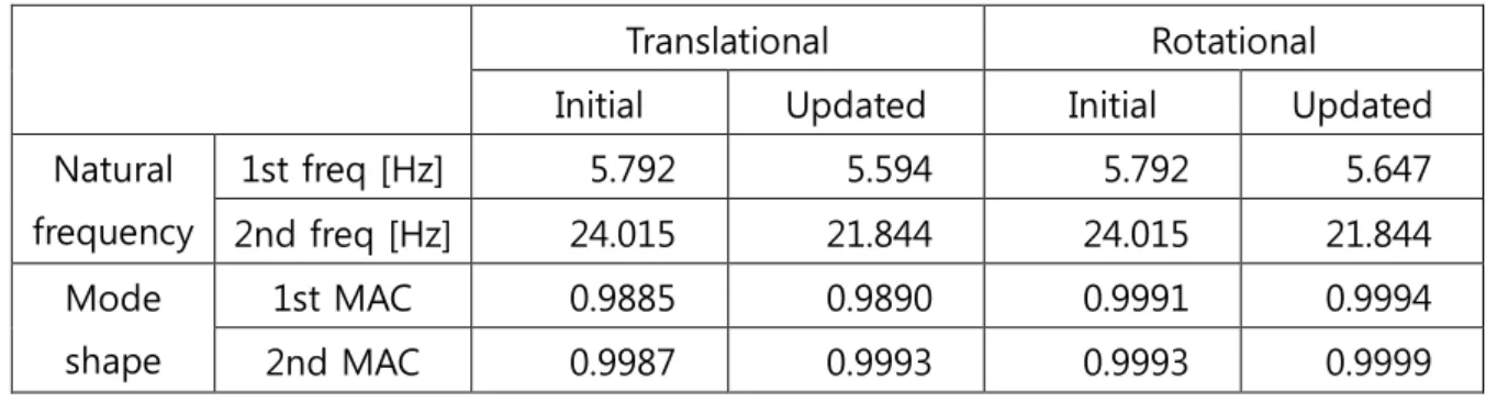
Comparison of FE Model Updating Performance
So far, the Finite Element model update using rotational response and translational response has been performed to maintain validity of FE model update using rotational responses. Analyzing the MAC sensitivity of rotational response to damage, FE model update using rotational response is verified by controlling the thickness of the beam in numerical simulation and in laboratory scale experiment. In the preliminary analysis, using the rotational response in FE model update, it is expected that the updated parameter will have more accuracy than using translational response, especially when the damage occurred near the boundary and a high-mode -form-answered objective function is useful in FEMU when the updated model is far from the initial one.
In numerical simulation, the use of rotational response is also evaluated to provide more efficient performance in updating FE models compared to the use of translational response. In the numerical simulation, the thicknesses of the beams of each element were accurately assessed with an error of less than 8% when using a rotation mode shape. However, in the experiment, the performance of updating the FE model when using rotational responses fell short of expectations based on preliminary work and simulation results, although the validity of using rotational response is achieved through the performance of using translational response to be compared in experiments.
And not only the thickness of each element, but also the mass of each element with sensors are selected as parameters to be updated when updating the finite element model. Jennewein and T Kiefer, “Damage detection based on model updating methods”, Mechanical Systems and Signal Processing, vol. Xia, “Dynamic evaluation of a curved cable-stayed bridge by model updating,” Journal of Structural Engineering-ASCE, vol.
De Roeck, “Damage assessment by updating an FE model using damage functions,” Computers & Structures, vol. Lu, “Highway bridge superstructure evaluation using dynamic testing and finite element model updating,” Journal of Bridge Engineering-ASCE, vol. Ren, “Damage detection by finite element model updating using modal elasticity residual,” Journal of Sound and Vibration, vol.
Create Identification of a composite beam using finite element model updating.Computer-Aided Civil and Infrastructure Engineering.
CONCLUSION