Until now, increased radiation was not the main concern of nuclear power plant safety criteria due to the phenomenon of corrosion. In extensive research, to understand the individual effects of the sink (grain boundary and loop and displacement line, texture) on the growth mechanism, radiation growth of single-crystal experiments was done.
General background
The goal and scope of this study
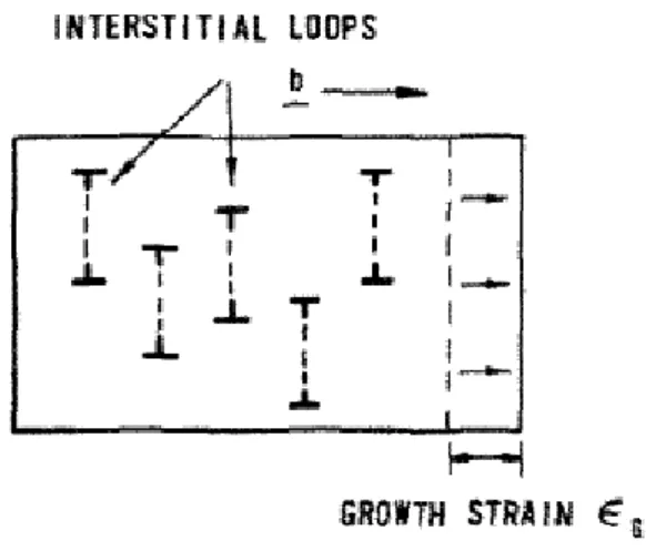
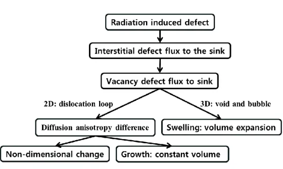
Radiation-induced dimensional change
For this understanding, it must be considered as the basis of the mechanism of the radiation-induced phenomenon. Therefore, the conventional analysis for the cubic system could not be used to fundamentally understand the radiation-induced phenomenon in zirconium.
Radiation-induced growth
Single crystal zirconium
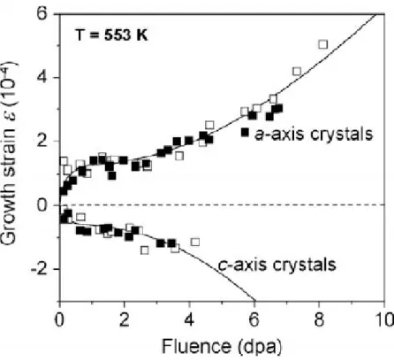
However, in the stationary and dissociation phase, the growth strains shown are difficult to distinguish from the iodide-purified ones. In both cases of iodide-refined and zonal zirconia, c-axis growth could not be identified in this fluence range.
Polycrystalline zirconium
Zircaloy-2 and Zircaloy-4
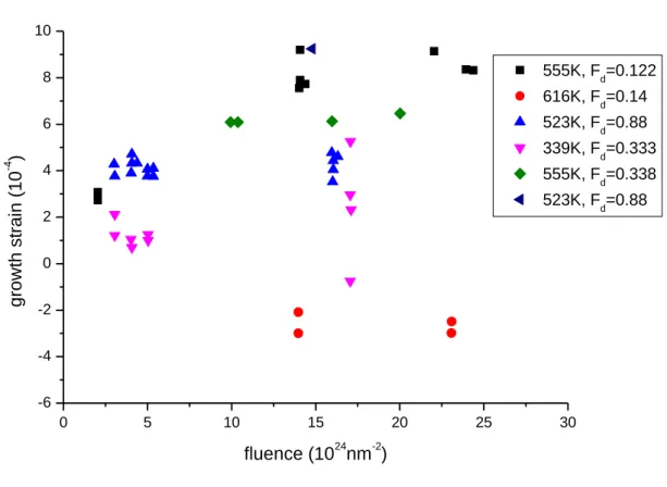
At an f-factor around 0.33 relatively low growth strain is shown compared to other f-factor values. The growth behavior of 25% cold worked zircaloy shows breakout area and higher growth strain than annealed zircaloy-2.
Radiation-induced microstructure change
The fluence effect is maintained even at constant temperature; before the dislocation loops of the
![Fig II.11 Irradiation growth strain at 353 and 553 K in annealed and 25% cold-worked zircaloy-2 [28]](https://thumb-ap.123doks.com/thumbv2/123dokinfo/10537369.0/25.892.482.680.355.547/fig-irradiation-growth-strain-annealed-cold-worked-zircaloy.webp)
Radiation-induced growth mechanism
Single crystal zirconium
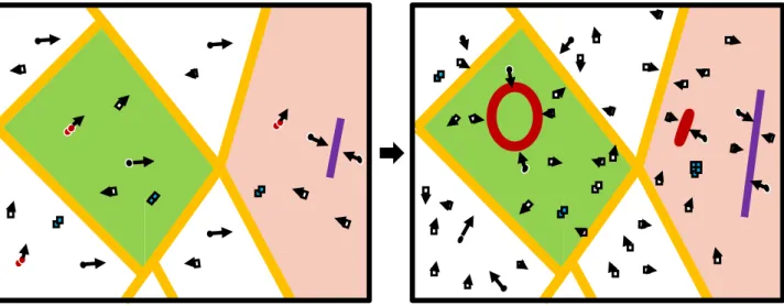
In the first stage of irradiation growth, the dislocation and the dislocation loop are a bias sink because the SIA diffusion coefficient is much higher than the vacancy diffusion coefficient, that is, in the middle stage the dislocation and the dislocation loop become a neutral sink because the vacancy concentration increases rapidly.
Annealed polycrystalline zirconium
Cold worked polycrystalline zirconium
Defect rate equation
Primary radiation damage
These mechanisms can also be classified into two parts: one is the neutron-matrix interaction, which means PKA (primary knock on atom) is generated. Where N is the lattice atom density, Ф(Ei) is the energy-dependent particle flux, and σD(Ei) is the energy-dependent displacement cross section.
Simple balance equation
Radiation-induced growth strain equation
Irradiation growth is expressed by time-dependent due to defect number density could be replaced by dislocation growth rate. Here, 𝜌𝑚 is dislocation sink density, 𝑉𝑚 is dislocation rise rate, 𝑏𝑚 is burger vector, and cos2𝜑𝑚 is angle between c axis and sink direction.
Radiation-induced growth models
- Carpenter’s model (1975)
- Dollins’s model (1978)
- FSP’s model (1978)
- Christen’s model (2008)
- Golubov’s model (2008)
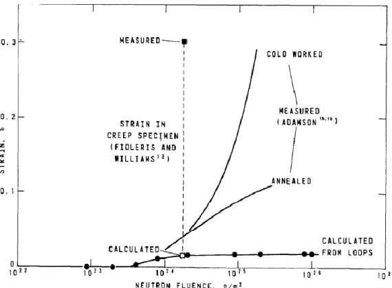
Before the development of the irradiation growth model, which is based on rate theory, the experimental growth prediction model was established by using loop growth. At that time, by measuring the defect size and concentration, it could know that the existing point defect in the matrix effect on the irradiation growth is negligible. Finally, the defect irradiation growth is calculated by two sources that direct the accumulation of defects and cluster defects onto the dislocation loop.
In the early stage of the growth research field, defect rate theory and microstructure information are being developed, and irradiation growth modeling has been made possible from these efforts. However, in the polycrystalline case, the dislocation loop is not the main sink contributing to the irradiance growth. Before 3dpa, it was assumed that the dislocation loop
Thus, dislocation can be used conceptually to analyze irradiation growth in zirconium and its alloys.
Improved defect rate equation
Single crystal zirconium
To calculate the growth deformation, it must calculate the concentration of defects. In the case of single crystal zirconia, the dislocation loop and dislocation line are the main sink in the matrix. Therefore, the defect rate equations could be easily constructed for defect generation, recombination, and sink loss, such as the dislocation loop and line. 𝑍𝑖𝑙𝑝𝑖 and 𝑍𝑖𝑙𝑝𝑣 are the SIA and the SIA loop vacancy deviation factor, 𝑍𝑑𝑝𝑖 and 𝑍𝑑𝑝𝑣 are the SIA and the dislocation line vacancy deviation factor, 𝑍𝑣 𝑙𝑏𝑖 and 𝑍𝑣𝑙𝑏𝑣 are the SIA and the unoccupied loop vacancy deviation factor, free deviations jobs line.
𝐶𝑠𝑖 and 𝐶𝑠𝑣 are defect concentration of SIA and void in single crystal matrix, 𝐷𝑖 and 𝐷𝑣 are diffusion coefficient in the matrix. The rv and ri are dislocation loop radius of vacancy and interstitial and Nv and Ni are dislocation loop number density of vacancy and SIA. Change of the total number of dislocation loops is also proportional to the probability of defect interaction.
In this modeling case, dislocation loop generation and saturation behavior must be taken into account.
Polycrystalline zirconium
Therefore, in this equation, radiation growth is calculated with zinc strength multiplication and defect flux and anisotropy factor. After establishing defect rate equation and growth strain equation, defect concentration and radiation growth results are calculated by python code program. In the case of cold-worked polycrystallines, radiation growth did not agree well with experimental data.
However, in the case of irradiance growth data, the figure was edited by ORIGIN program to compare with experiment data. In the results chapter, defect concentration, defect flux, zinc strength and radiation growth strain results are explained. In the case of the radiation growth strain equation, the
However, in the case of the annealed polycrystalline case, the irradiation growth result does not agree well with the experimental results.
Improved radiation-induced growth equation
Single crystal zirconium
In the case of single crystal, the irradiation growth equation is simple compared to the polycrystalline one because a-axis elongation and c-axis shortening could be expressed directly. In this equation, 𝜖𝑎𝑖𝑙𝑝, 𝜖𝑎𝑑𝑝, 𝜖𝑎𝑣𝑙𝑏, 𝜖𝑎𝑑𝑏 is radiation line dislocation growth in SIA line displacement, parallel to plane growth in prism-plane strain , vacancy dislocation loop in basal plane and dislocation line parallel to basal plane, 𝐴𝑎𝑙𝑏, 𝐴𝑎𝑑𝑏 is strain average factor for each sink, 𝜌𝑖𝑙𝑝, 𝜌𝑑𝑝, 𝜌𝑣𝑙𝑏, 𝜌𝑑𝑏 are each zinc density. 𝑍𝑖𝑙𝑝𝑖 and 𝑍𝑖𝑙𝑝𝑣 are SIA and vacancy bias factor for SIA loop, 𝑍𝑑𝑝𝑖 and 𝑍𝑑𝑝𝑝𝑝 𝑏𝑖 and 𝑍𝑣𝑙𝑏𝑣 are SIA and vacancy bias factor for vacancy, 𝑍𝑑𝑏𝑖 and 𝑍𝑑𝑏𝑣 are SIA and vacancy bias factor for dislocation line and 𝜖𝑎 is total load of -axis radiation growth.
And the average load factor is growth load ratio with axis and
Polycrystalline zirconium
However, in polycrystalline cases, the bias factor must be changed once more due to the enhanced grain boundary diffusion.
Improved radiation-induced growth modeling results
Single crystal zirconium
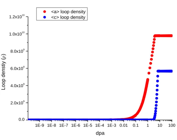
And after the accumulation of point defects, the recombination rate can affect the defect concentration because the recombination rate increases with the increased defect concentration. However, sinks downstream of this steady-state region caused by recombination have another loss effect on the defect concentration. At the first stage, the densities of both loops are similar, but after 0.1 dpa the dislocation loop increases dramatically and the
Because in the early stage, as mentioned before, the SIA diffusion coefficient is much faster than the vacancy, the net sinking defect flux is much higher than other dpa regions.
Annealed zirconium
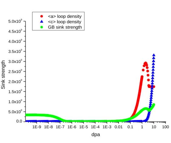
At the first stage, both loop densities are rows, however, the grain boundary sink strength has a certain value. After 10−9 dpa, however, the grain boundary sink strength is dramatically reduced close to 0 cm−2 at 0.1 dpa. And after this region of low sink strength, both the loop and grin limit increases due to loop generation.
And after 1 dpa,
The results show behavior similar to the first phase of the single-crystal case, because in the case of mature polycrystalline grains, the polycrystalline grain boundary plays as a vacancy sink.
Cold worked zirconium
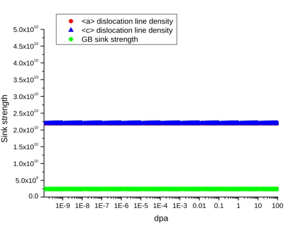
Since the main sink of cold-worked polycrystals is the dislocation line and grain boundary, three types of sinks are studied. Therefore, the dislocation line density could not be increased because the dislocation line develops into a lattice dislocation. In the case of the behavior of the net flow of defects towards the sink, three types of defects are also analyzed because the main sinks are the dislocation line and the grain boundary.
Unlike monocrystalline and annealed polycrystalline case, the defect flow to the sink is reduced in the first stage. In the case of cold-worked polycrystalline zirconia, the sinking strength is high enough to consume the defect concentration at an early stage because the dislocation lines already exist before irradiation.
FEM modeling
However, growth modeling is very difficult because it is necessary to combine this error rate equation and the growth deformation equation due to irradiation. From the experimental results, the general characteristic of irradiation growth is understood, such as the relationship of behavior (fluence, temperature and texture). Fidleris, "Summary of Experimental Results on Reactor Creep and Irradiated Growth of Zirconium Alloys," ATOM.ENERGY REV., vol.
MURGATROYD, "EFFECT OF TEXT AND TEMPERATURE CYCLES ON IRRADIATION GROWTH IN COLD WORKED ZIRCALOY-2 BY 353 and 553 K," Journal of Nuclear Materials, vol. ZEE, "HOË FLUENCE IRRADIATION GROWTH IN ENCRYSTAL ZIRCONIUM AT 553 K," Journal of Nuclear Materials, vol. Barbu, "Cluster dynamics modeling of irradiation growth of sirkonium single crystals," Journal of Nuclear Materials, vol.
Adamson, "Summary of Experimental Results on Reactor Creep and Radiation Growth of Zirconium Alloys," Atomic Energy Review.
Single crystal python code structure
Polycrystalline python code structure
Constant, bias factor at the grain boundary in the basal plain Zigbee = 0.586 # Constant, bias factor at the grain boundary in the basal plain.
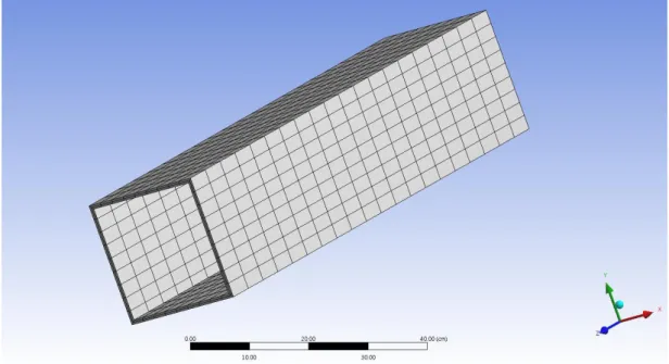
FEM modeling of radiation-induced growth
Fuente C:\Poruhárape\CSI\Escritorio\zircaloy-4 Ñemboheko FEM medel\zircaloy- 4(estructura guía)-1_archivo\dp0\SYS\DM\SYS.agdb. Solución Archivokuéra ryru C:\Users\CSI\Desktop\zircaloy-4 Pojoapy puruhára rehegua FEM medel\zircaloy- 4 (estructura ñembohekorã)-1_files\dp0\SYS-1\MECH\.
![Fig II.5 Irradiation growth strain at 553K in annealed iodide and zone-refined zirconium single crystals [13]](https://thumb-ap.123doks.com/thumbv2/123dokinfo/10537369.0/17.892.205.713.661.1062/irradiation-growth-strain-annealed-iodide-refined-zirconium-crystals.webp)
![Fig II.6 Irradiation growth strain at 353 K in annealed polycrystalline iodide zirconium [16]](https://thumb-ap.123doks.com/thumbv2/123dokinfo/10537369.0/18.892.208.704.640.1052/fig-irradiation-growth-strain-annealed-polycrystalline-iodide-zirconium.webp)
![Fig II.7 Irradiation growth strain at 553 K in annealed polycrystalline iodide zirconium [16]](https://thumb-ap.123doks.com/thumbv2/123dokinfo/10537369.0/19.892.183.691.195.652/fig-irradiation-growth-strain-annealed-polycrystalline-iodide-zirconium.webp)
![Fig II.8 Irradiation growth at 555 K in cold worked zircaloy-4 [11]](https://thumb-ap.123doks.com/thumbv2/123dokinfo/10537369.0/20.892.182.710.552.986/fig-ii-irradiation-growth-555-cold-worked-zircaloy.webp)