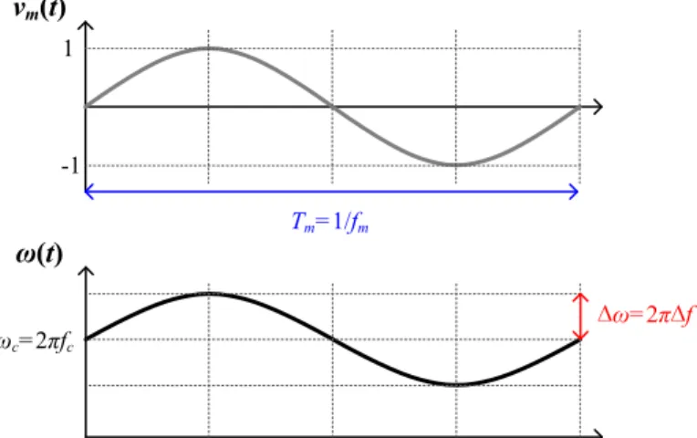
Theoretical output voltage fluctuation of the buck converter with CCM and DCM according to the frequency variation. Waveforms of the output power of the series resonant converter with the periodic modulation: (a) in time domain, (b) in frequency domain.
Introduction
However, the conventional output power balancing method concentrates the power loss on the low-efficiency modular converter, so it accelerates the aging of a specific converter. Based on the input power balancing strategy, a hybrid input power balancing method will be introduced for the IPOP modular converters.
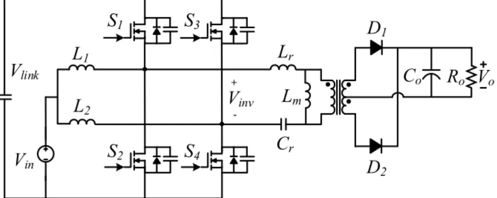
DC/AC Series Resonant Converter with Wireless Power Transfer Capability
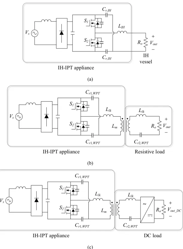
- Introduction to IH-WPT dual-functional appliance
- Power stage configurations of IH-WPT dual-functional appliance
- Control method of IH-WPT dual-functional appliance
- Design constraints of IH-WPT dual-functional appliance
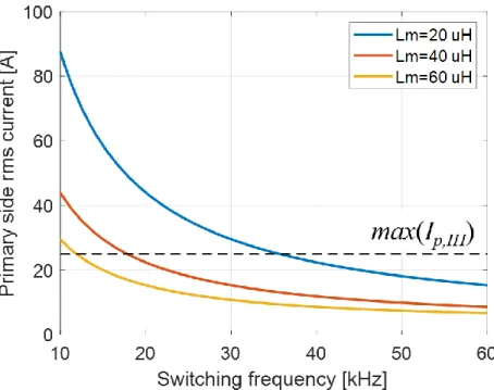
- Available primary side current limitation
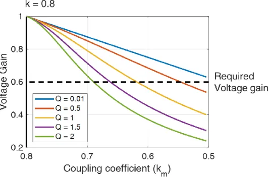
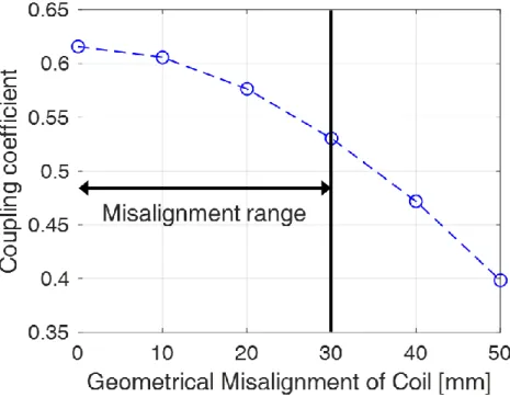
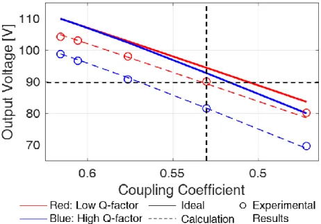
- Misalignment tolerance of WPT mode
- Design methodology of IH-WPT dual-functional appliance
- Resonant network design for WPT mode
- Design example
- Experimental results of IH-WPT dual-functional appliance
- Prototype development
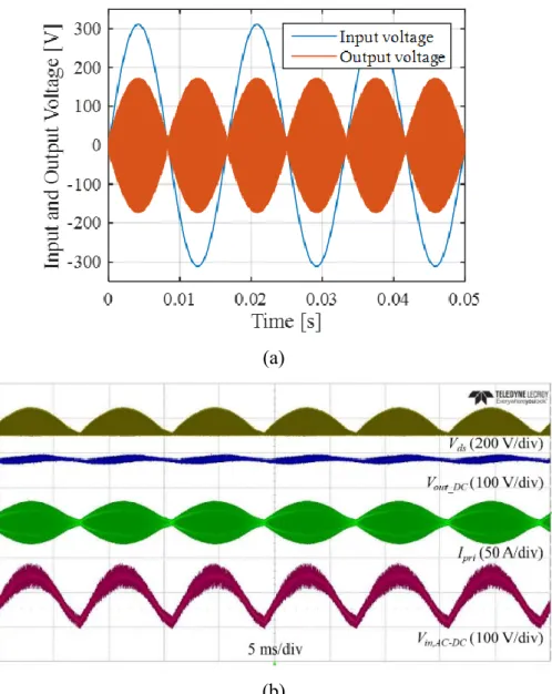
- Steady-state waveforms of IH-WPT prototype
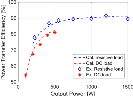
- Performance verification of IH-WPT prototype
2-14 shows the power transfer efficiency of the IH-WPT device according to the output power. 2-15 shows the power loss analysis of the IH-WPT device under the full load condition.
DC/DC and DC/AC Converters with Spread Spectrum Technique
Introduction to spread spectrum technique
Theoretical analysis of spread spectrum technique
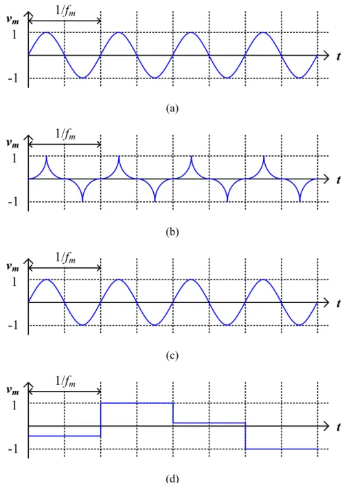
- Frequency modulation
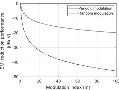
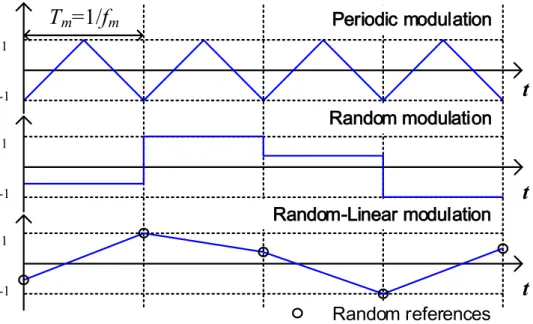
- Peak attenuation performance according to modulating waveforms
- Peak attenuation performance according to the modulation index
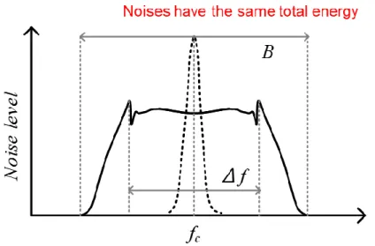
- Practical considerations: Resolution of bandwidth
- Practical considerations: Output voltage fluctuation
- Practical considerations: Output power fluctuation
Frequency modulation of SST by modulating waveform, frequency variation and modulating frequency. 3-5 compares the peak attenuation performance of periodic (triangular wave) and random modulations in the ideal condition. The peak attenuation performance of the periodic modulation is proportional to the frequency change considering the fixed RBW.
The peak damping performance of the random modulation is proportional to the frequency variation considering the fixed RBW. -10) where Vo,pp,CCM and Vo,pp,DCM are the output voltage fluctuations of the buck converter with the CCM and the DCM respectively. -10 shows the output voltage fluctuation of the buck converter according to the frequency variation of the SST.
-11 shows the simulation results of the moderate value converter with CCM and DCM using periodic modulation. -12 shows the simulation results of the moderate value converter with CCM and DCM using random modulation. -13 shows the output power of a moderated converter with DCM using periodic and random modulations in the time domain.
Performance enhancement of output voltage regulation for DC/DC converters using
- EMI mitigation for PV power generation system
- Power stage analysis of IBI LLC resonant converter
- Output voltage fluctuation minimization using dual feedback control
3-17 (a) and (b) show the main operating waveforms of the IBI LLC resonant converter for analyzing the input-to-output voltage gain. The voltage gain of the IBI LLC resonant converter is dependent on both the duty ratio and the switching frequency. Since the switching frequency changes periodically in accordance with the SST, the major control variable for the IBI LLC resonant converter is the duty cycle.
The resonant network design with high inductor ratio and low quality factor can reduce the output voltage fluctuation of the IBI LLC resonant converter using the SST. The zero voltage switch (ZVS) region of the inverter is determined by the inrush current of the lower side switches (S2 and S4) regardless of the operating condition for the IBI LLC resonant inverter. 3-25 (a) shows the operating waveforms of the IBI LLC resonant converter without the SST under the full load condition.
3-25 (b) shows the operating waveforms of the IBI LLC resonant converter with the SST under full load. 3-25 (c) shows the operating waveforms of the IBI LLC resonant converter with the SST and dual feedback control under full load. Figures 3-26 (a) and (b) show the operating waveforms of the IBI LLC resonant converter with the SST and dual feedback control in the transient state.
Audible noise elimination method for DC/AC converters using random modulation
- Introduction to random-linear frequency modulation
- Peak attenuation performance comparison
- Audible noise comparison
- Design methodology of random-linear modulation
- Experimental verification of random-linear modulation
The peak damping performance of the random-linear modulation has the same trend as the random modulation. Therefore, the peak damping performance of the random-linear modulation can be improved, which is proportional to the modulating frequency. The output power of the series resonant converter can be simplified with sinusoidal waveforms as follows:
3-32 shows the output power of the series resonant converter with the periodic modulation in steady state. 3-34 shows the output power of the series resonant converter when the switching frequency changes drastically. 3-35 shows the frequency variation of the random-linear modulation using a practical digital signal processor (DSP).
Therefore, the maximum frequency variation of the random linear modulation is limited by the pre-designed resonant network of the series resonant converter, as follows: The change in the switching frequency that causes the audio noise depends on the physical structure of the series resonant converter and the pot. 3-40 shows the results of the audio spectrum analysis of the sound of a series resonant converter with periodic modulation, random modulation, and random-linear modulation.
DC/DC Converters with Modular Operation
Introduction to modular operation and power balancing methods
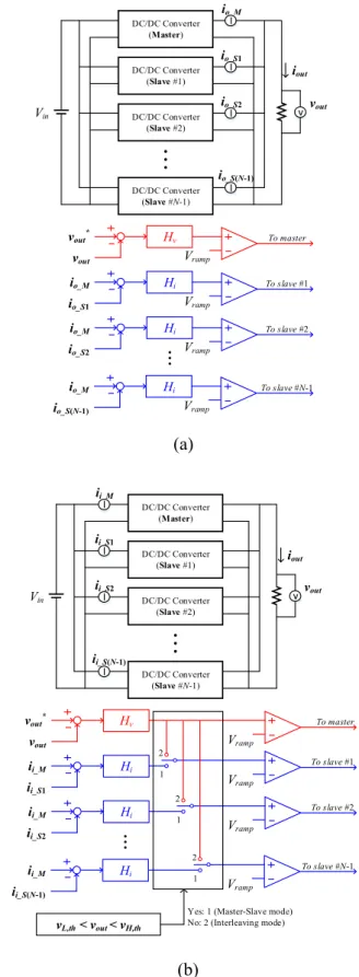
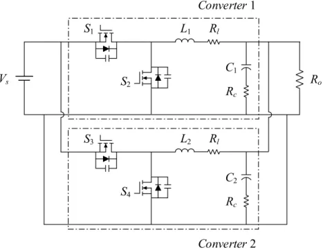
Operation schemes of IPOP modular current converters: (a) Output power balancing method, (b) Hybrid input power balancing method. Unlike the output power balancing method, the input power balancing can provide improved power loss balancing capability. Therefore, the hybrid input power balancing method can increase the whole power conversion efficiency and reduce the power loss concentrated on the lowest efficiency converter, which not only improves the performance of the modular inverters, but also provides the longer life and the higher reliability than the conventional method.
In the transient state, where the output voltage deviates from the threshold values, the hybrid input power balancing method operates the interleave mode to provide a tight output voltage regulation performance. The entire modular converters share the voltage control loop, which has higher dynamic performance than the current control loops of the slave converters. Therefore, it can improve the whole dynamic performance of the modular structure and can avoid the current oscillation between the modular converters in the transient state.
Performance enhancement in steady-state
- IPOP modular converters with output power balancing method
- IPOP modular converters with hybrid input power balancing method
- Performance comparison
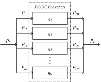
The hybrid input power balancing method checks the input power of IPOP modular converters as balanced. Therefore, the input and output power of IPOP modular converters with the hybrid input power balancing method can be calculated as follows: 4-3 shows the difference of the whole power conversion efficiencies using the output power balancing and the hybrid input power balancing methods (ηT,I-ηT,O).
The hybrid input power balancing method can achieve the same or higher energy conversion efficiency than the output power balancing method, as shown in (9). The power losses of the two power converters are well distributed by using the hybrid input power balancing method. As a result, the hybrid input power balancing method can not only increase the overall power conversion efficiency of the full modular IPOP converters and reduce the power loss difference between the converters.
It is an important benefit of the hybrid input power balancing method to improve the lifetime and improve the reliability of the entire power conversion system. The difference of the total power conversion efficiency between the hybrid input power method and the output power balancing method (ηT,I- ηT,O). Distribution of power losses between IPOP power converters: (a) Output power balancing method, (b) Hybrid input power balancing method.
Performance enhancement in transient-state
- Loop gain comparison using a case study with IPOP buck converters
- Dynamic performance comparison using simulation results of IPOP buck
4-7 shows the loop gains of the master-slave input and output power balancing methods and the interleaved operation. According to (4-18), the voltage control loop gain of the master-slave operation consists of Tm and vo,s. It can maintain the stability of the entire voltage control loop and the controllability of the high voltage.
The voltage control loop gain of the interleave operation can obtain a larger magnitude and higher crossover frequency than that of the master-slave input and output power balancing methods. Figures 4-8 (a) and (b) show the transient response of the modular IPOP converters using the master-slave input and output power balancing methods. In addition, the master-slave input power balancing method has a longer current oscillation settling time because it has a lower current control crossover frequency than that of output power balancing, as shown in Figure 2.
4-8 (c) shows the transient response of modular IPOP converters using the hybrid input power balancing method. 4-8, the hybrid input power balancing method can improve the dynamic performance of modular IPOP converters with shorter settling time. In addition, the threshold values that determine the operation modes of the hybrid input power balancing method also affect the stability of the entire modular IPOP converters.
Experimental verification of hybrid input power balancing method
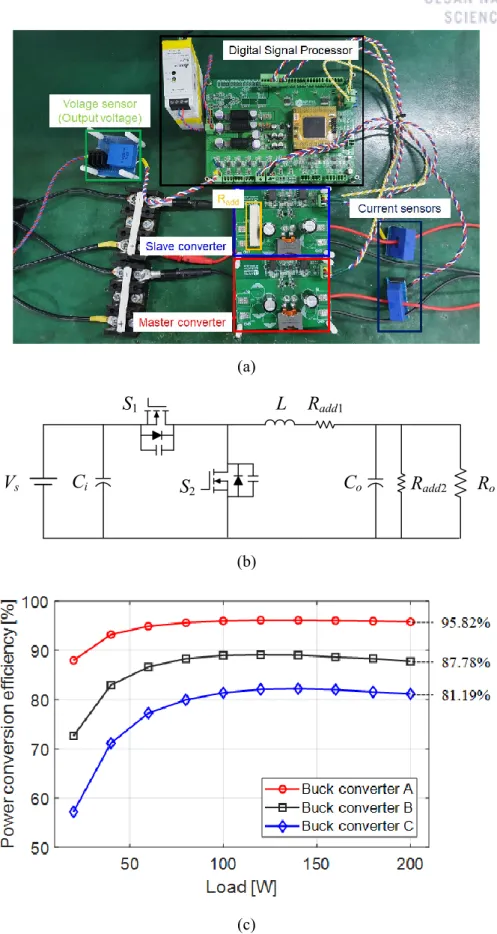
- Prototype development
- Experimental results in steady-state
- Experimental results in transient-state
Steady state operation waveforms of modular buck converters: (a) Using output power balancing method, (b) Using hybrid input power balancing method. 4-11 shows the steady-state operating waveforms of modular load converters using the output power balancing method and the hybrid input power balancing method. 4-12 compares the overall power conversion efficiency of modular buck converters using the output power balancing method and the hybrid input power balancing method.
Efficiency curves of low-power modular converters using the output power balancing method and the hybrid input power balancing method according to the load condition: (a) Experimental case 1 (Buck converter A and B), (b) Experimental case 2 (Buck converter A and C) ), (c) Experimental case 3 (Buck converter A, B and C). Compared with the output power balancing method, the hybrid input power balancing method can reduce the overall performance. Thermal images of modular inverters operating at full load: (a) Output power balancing method, (b) Hybrid input power balancing method. temperature of the entire system.
Step input response of modular buck converters from 48 V to 36 V using hybrid input power balancing method. 4-15 shows the step input response of the modular buck converters using the hybrid input power balancing method. The hybrid input power balancing method can notice the sudden input voltage change by observing the output voltage fluctuation.
Conclusion
Conclusion and summary
Finally, experimental results using IPOP modular converters verify the performance improvement of the hybrid input power balancing method. Modular converters using the hybrid input power balancing method can achieve high power conversion efficiency, balanced distributed power loss and improved dynamic performance without any current increase.
Future works
Jung, “Load adaptive modulation of a series resonant inverter for all-metal induction heating applications,” in IEEE Transactions on Industrial Electronics, vol. Burdio, “Quantitative evaluation of induction efficiency in residential induction heating applications,” in IEEE Transactions on Magnetics, vol. Burdío, “Class-D/DE Dual-Mode-Operation Resonant Converter for Improved Efficiency for Domestic Induction Heating System,” in IEEE Transactions on Power Electronics, vol.
Batarseh, “Review of Multiport Converters for Solar and Energy Storage Integration,” in IEEE Transactions on Power Electronics, vol. Morrow, “Three-port DC–DC converter for stand-alone photovoltaic systems,” in IEEE Transactions on Power Electronics, vol. Xiang, “Power control of asymmetric frequency modulation in a resonant inverter in a full bridge series,” in IEEE Transactions on Power Electronics, vol.
Puyal, “Inverse-based power control in indoor induction-heating applications,” in IEEE Transactions on Industrial Electronics, vol. Viverge, "Failure prediction of electrolytic capacitors during moderate power supply operation," in IEEE Transactions on Power Electronics, vol. Tavner, “Condition Monitoring for Device Reliability in Power Electronic Converters: A Review,” in IEEE Transactions on Power Electronics, vol.