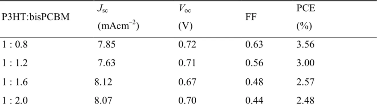
In the case of P3HT:bisPCBM of 1 : 0.8 w/w, more balanced electron mobility and hole mobility are observed, resulting in better performance of the solar cells. Under the best balance conditions, such as P3HT:bisPCBM at 1 : 0.8 w/w, the solvent annealing is used to further clarify the optimization of the devices. From this experiment, it can be concluded that the best power conversion efficiency of 3.75% is achieved in a layered structure of P3HT:bisPCBM of 1:0.8 w/w for a solvent annealing time of 24 h. WE YOU.
Absorption spectra of pure P3HT (dashed line) without solvent annealing and P3HT:bisPCBM blend film with different solvent annealing times on fused silica, without solvent annealing (solid line), solvent annealing for 2 h (dashed dashed line), 24 hours (short dotted line), 48h (dashed line). Surface morphology and surface profile of P3HT:bisPCBM (1:0.8w/w) blend films with different solvent annealing times obtained by tapping in AFM mode. Photovoltaic parameters of devices with different P3HT:bisPCBM mass ratios according to 2 h solvent annealing.
Calculated electron and hole mobility values based on dark current densities and active layer thickness values for P3HT:bisPCBM devices with different weight ratios at 2 hours of solvent annealing. Photovoltaic parameters of the devices with different P3HT:bisPCBM weight ratios according to different solvent annealing and 48 h).
List of Schemes
The HOMO and LUMO level of BHJ solar cell materials
The structure of bisadduct of phenyl C 61 –butyric acid methyl ester
The flow chart of experimental process
- Introduction
- The history of organic solar cells
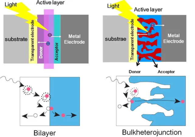
- The structure of organic solar cells
- The principle of organic solar cell
- The progress of organic solar cells
- Experiment
- Materials
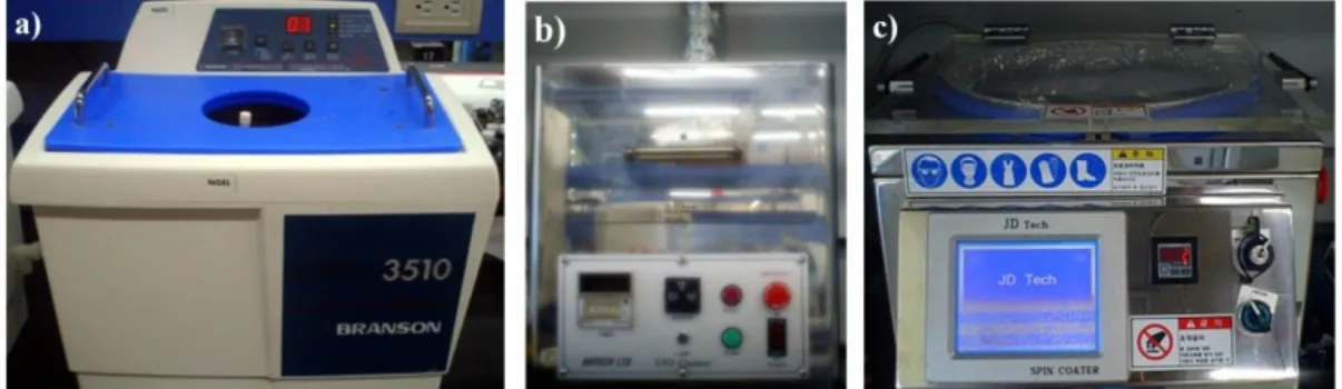
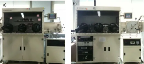
- Device Fabrication
- Solvent annealing treatment
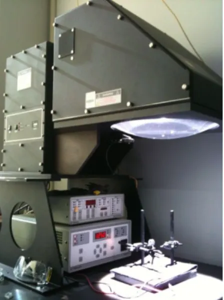
- Device characterization
- Results and discussion
- J–V characteristics of optimal ratio and solvent annealing time
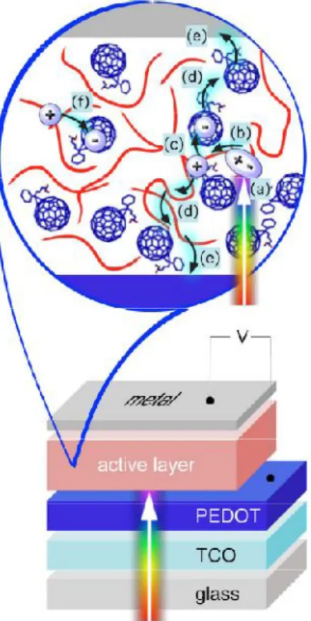
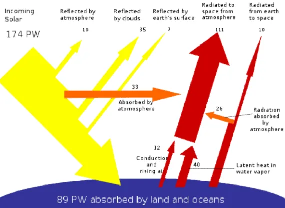
For practical use, not only the PCE is important, but also the lifetime of the photovoltaic device. At least one of the electrodes must be transparent to allow photoexcitation of the active materials. Basic steps in the process of photoinduced charge separation for donor (D) and acceptor (A). 1) donor photoexcitation (2) exciton diffusion and electron-hole pair recombination formation, direct charge separation by charge transfer, electron transfer within the incident pair to form a geminate pair (4) charge separation.
62 Contrary to previous assumptions, the electric field in that study mainly assisted in the formation of the bonded pairs and not in dissociation. In P3HT and related alkyl derivatives, the nature of the charge carriers and the mechanism of charge transport have been extensively studied. Depending on the morphology of the donor and acceptor interface relative to the respective electrodes, diffusion or drift may dominate.
Additional study is needed to understand the theory of the nature of charge carriers in conducting polymers and their relationship to molecular packing. The simplest description for charge extraction would be a hopping 71 or tunneling 72 step, from the organic material HOMO level of the donor for. 73 However, in real devices, charge extraction is a much more complex problem, due to the morphological and chemical nature of the organic–electrode interface.
84 Recently, many p-type conjugated polymers with suitable low bandgap have been synthesized to cover more fraction of the solar spectrum, resulting in increased Jsc. Voc is determined by the difference between the energy levels of the highest occupied molecular orbital (HOMO) of the electron donor and the lowest unoccupied molecular orbital (LUMO) of the electron acceptor in conventional BHJ solar cells. 88 In the case of P3HT, this energy gap is much higher at about 1.1 eV and therefore results in a less than optimal Voc, as the open circuit voltage is mainly limited by the difference between the HOMO of the donor and the LUMO of the acceptor . .
88 Although this observation may lead to arguments against the use of bisPCBM,90 it is still a substantial candidate for electron acceptor in the polymer solar cell industry, as it allows a significant improvement in Voc. The bisPCBM fraction was separated from the rest of the product mixture using standard column chromatography. Small amounts of solvent (DCB) were added to the petri dish to slow the evaporation rate.
The fill factor (FF) was calculated by FF = (VmaxJmax)/(JscVoc), where Vmax and Jmax are the voltage and current density at the maximum power point of the I – V curve in the fourth quadrant. XRD (Rigaku Cu Ka 3 kW) spectra of the different samples were obtained by spin coating on glass.
Current density (mA/cm2)
Voltage (V)
Mobility
For higher efficiency polymer BHJ solar cells, the mobility of electrons and holes in the polymer blends is an important parameter that must be well controlled, because balanced charge carrier transport is an essential condition for increasing the FF. 91 The mobility of electrons and holes can be calculated from the space charge limited current (SCLC) by eqn (1). 92. The trend of electron and hole mobility in P3HT:bisPCBM films shows a clear similarity to that in P3HT:PCBM, however, both mobilities show relatively low values, compared to the reported P3HT:PCBM films with 1:0, 8 w/w (μelectron or μhole = ~ 10–8m2V–1s–1, respectively).
94 Such mobility degradation in P3HT: bisPCBM can be largely attributed to the large number of bisPCBM isomers that can suppress the desirable bicontinuous interlocking networks of the BHJ composite. As the relative weight amount of bisPCBM increased in the mixture, the difference between electron and hole mobilities was noticeably more pronounced. From mechanistic considerations of the balanced transport of holes and electrons in solar cells, it is concluded that P3HT:bisPCBM 1 : 0.8 w/w is the optimized ratio configuration.
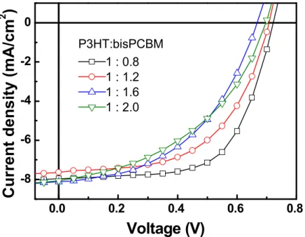
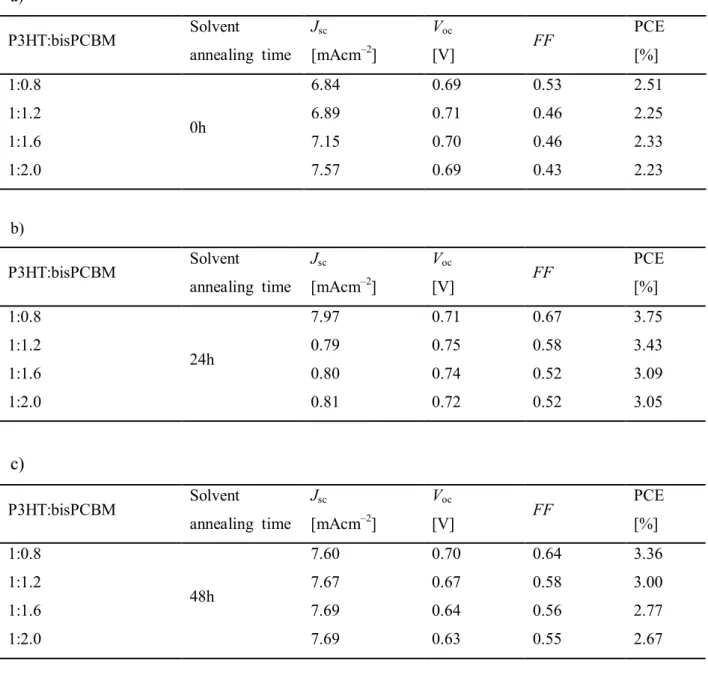
To assess the solvent annealing effect, the J-V characteristics of the optimal P3HT:bisPCBM system at a ratio of 1:0.8 w/w are systematically studied as a function of the controlled annealing times and 48 h (Figure 11). Series resistances (Rs) and shunt resistances (Rsh) are calculated using J-V curves. The optimal results are obtained after 24 hours of solvent annealing, as shown in Table 4. Note that in the experiment (Table 4) the best solar energy The cell yield obtained is for P3HT:bisPCBM with an annealing time of 24 hours.
Current Density (mA/cm2)
J–V characteristics of other ratio and solvent annealing time
All the data show that the best ratio is 1:0.8, so it can be clarified that the optimal ratio is 1:0.8 and the curing time of the solvent is 24 hours. First, the fabrication of devices for different ratios without solvent annealing treatment is carried out (Table 5a and Figure 12a). The ratio for 1:0.8 shows the best power conversion and is the same as the other conditions.
The results of the solvent annealing time for 2 hours are attached in Table 2 and Figure 9, the ratio 1:0.8 is selected from all data and then collected in Table 4 and Figure 11. Photovoltaic parameters of the devices with different P3HT:bisPCBM weight ratio according to different solvent annealing (0.24 and 48h). one).
X–ray diffraction
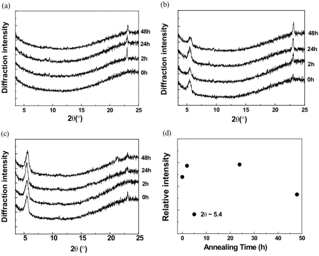
As shown in the change of relative intensities at 2θ=5.4o of the P3HT:bisPCBM film in Fig. 13d, the peak height increases with solvent annealing time up to 24 h, but gradually decreases with further extended annealing time. This suggests that solvent annealing of the P3HT:bisPCBM film for up to 24 h supports the increased formation of P3HT crystalline domains, but causes a negative effect on the P3HT:bisPCBM morphology within 24 h.
UV–vis absorption
Wavelength (nm)
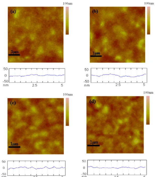
The physical topography of the P3HT:bisPCBM composite film (mass ratio, 1:0.8 w/w) with different solvent annealing times and 48 hours) observed by atomic force microscopy (AFM) is shown in Figure 15. Interestingly, that the surface in the 5 μm x 5 μm scan area is progressively rougher with a solvent annealing time of up to 24 h, but becomes smooth with an annealing treatment of 48 h. One possible conclusion is that solvent annealing times of up to 24 h may enable optimization of device performance in P3HT:bisPCBM, as the roughened surface can effectively reduce the charge-transport distance and increase Jsc as well as nanometer-scale texturing.
97 This concept is consistent with the XRD and UV-vis data described earlier.
Conclusions
2000, 'Monochromatic versus solar efficiency of organic solar cells', Solar Energy Materials and Solar Cells, vol. 1990, 'Effect of thin gold interstitial layer on the photovoltaic properties of tandem organic solar cell', Chemistry Letters, vol. 2009, 'Three-layer organic solar cell with a photoactive interlayer of coded pigments', Applied Physics Letters, vol.
2003, 'High performance polymer solar cells of an alternating polyfluorene copolymer and a fullerene derivative', Advanced Materials, vol. 2000, 'Stability and photodegradation mechanisms of conjugated polymer/fullerene plastic solar cells', Solar Energy Materials and Solar Cells, vol. 2009, 'Inverted bulk heterojunction organic photovoltaic device using a solution-derived ZnO substrate', Applied Physics Letters, vol.
39] Castro, Fernando A., Chabrecek, Peter, Hany, Roland & Nüesch, Frank 2009, 'Transparent, flexible and low-impedance precision fabric electrode for organic solar cells', physica status solidi (RRL) – Rapid Research Letters, vol. . 40] Thompson, Barry C & Fréchet, Jean MJ 2008, 'Polymer-Fullerene Composite Solar Cells', Angewandte Chemie International Edition, vol. 2001, 'Tracing the photoinduced electron transfer process in conjugated polymer/fullerene bulk heterojunctions in real time', Chemical Physics Letters, vol.
2003, 'The influence of the solvent on the crystal structure of PCBM and the efficiency of MDMO-PPV:PCBM 'plastic' solar cells', Chemical Communications, vol. 2007, 'Minimizing optical losses in bulk heterojunction polymer solar cells', Applied Physics B: Lasers and Optics, vol 2009, 'Probing transport properties in polymer/fullerene blends using time-of-flight photocurrent measurements', Applied Physics Letters, vol.
1998, 'Chemical potential shifts at electrodes of organic devices induced by grafted monolayers', Chemical Physics Letters, vol. 2009, 'Time-Dependent Evolution of Solar Morphology by Annealing Processes on Polymer:Fullerene Blend, Evolution of Solar Morphology by Annealing Process on Polymer:Fullerene Blend Solar Cells', Advanced Functional Materials, vol. 2009, 'Three-dimensional bulk heterojunction morphology for achieving high internal quantum efficiency in polymer solar cells', Advanced Functional.
2009, 'Three–dimensional bulk heterojunction morphology for achieving high internal quantum efficiency in polymer solar cells', Advanced Functional
2000, 'The effect of various heat treatments on the luminescence efficiency of polymeric light-emitting diodes', Advanced Materials, vol. 79] Ishii, Hisao, Sugiyama, Kiyoshi, Ito, Eisuke & Seki, Kazuhiko 1999, 'Energy Level Alignment and Interface Electronic Structures at Organic/Metal and Organic/Organic Interfaces', Advanced Materials, vol J 2006, 'New architecture for high-efficiency polymer photovoltaic cells using solution-based titanium oxide as an optical spacer', Advanced Functional Material, vol.
2004, 'Correlation between oxidation potential and open-circuit voltage of composite solar cells based on polythiophenes/fullerene derivative blends', Applied Physics Letters, vol. 2002, 'A low-gap semiconductor polymer for photovoltaic devices and infrared emitting diodes', Advanced Functional Materials, vol. 2003, 'Unification of hole transport in polymer field-effect transistors and light-emitting diodes', Physical Review Letters., vol.
J 2005, 'Correlation between structural and optical properties of composite polymer/fullerene films for organic solar cells', Advanced Functional Materials., Vol.
Publication
Presentation
Acknowledgement
감사의 글