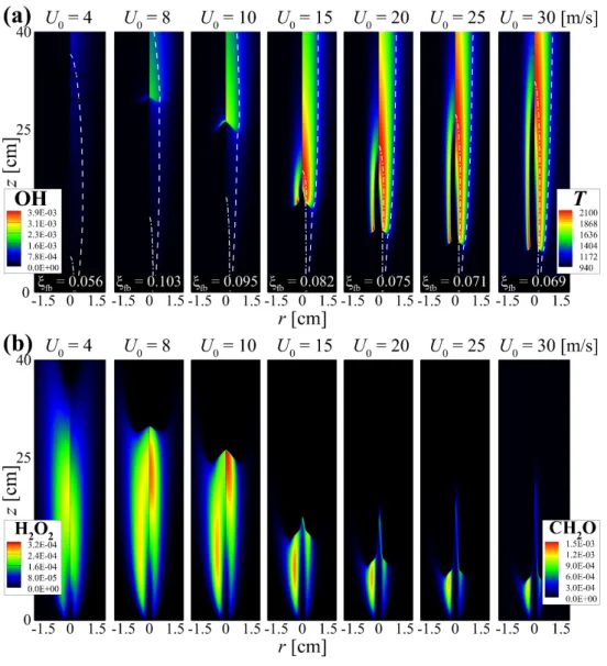
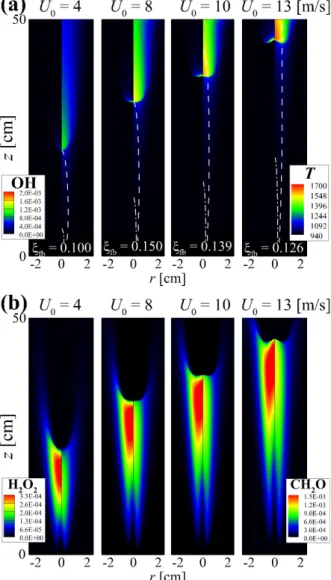
The properties of the flame structure and the stabilization of self-igniting laminar lifted n-heptane jet flames in heated coflow air are also investigated by performing 2-D numerical simulations. The dashed line represents the stoichiometric mixing fraction, ξst isoline; the value of the mixture fraction at the flame base, ξfb, for each U0 is shown in (a).
Laminar lifted jet flames under autoignitive condition
From previous studies of self-ignited laminar jet flames [22, 23], the variation of their HL has been intensively investigated, together with their flame structure characteristics. The main focus of the present study is to elucidate unusual launch and flame structure characteristics of self-ignited laminar lifted jet flames with different types of fuels.
![Figure 1.2: The iso-velocity and iso-mixture fraction lines on the r − z space several 1-D numerical studies for evaluating the reference flame propagation speed of lifted flames under autoignitive condition [16, 17], which verified that 1-D lifted flame c](https://thumb-ap.123doks.com/thumbv2/123dokinfo/10487579.0/29.892.301.591.126.375/velocity-fraction-numerical-evaluating-reference-propagation-autoignitive-condition.webp)
Turbulent lifted jet flames in autoignitive condition
They also demonstrated increased edge flame speed under autoignition conditions where autoignition-assisted flame propagation was found to be the primary stabilizing mechanism of raised flames. 41] performed 3-D large-eddy simulations (LESs) of turbulent spray combustion of n-dodecane under diesel engine conditions with different ambient temperatures and concluded that the stabilization mechanism of raised flames differs from the spread of the flame with the help of autoignition in autoignition as the ambient temperature decreases.
Negatively propagating edge flame
In this study, we propose a new technique to reduce the buoyancy effect in counterflow unmixed flames with low strain rates. Furthermore, we mainly investigate the stabilization and quenching dynamics of unmixed flames against low strain rate flow to better understand the characteristics of the negatively propagating edge flame.
Scope and objective
Another unusual 'U'-shaped lift height variations of self-igniting DME jet flames is studied in Chapter 4. In Chapter 5 the flame lift-off height, flame structure and stabilization characteristics of self-igniting n-heptane jet flames are discussed.
Constitutive relationships
The stress tensor, τβα, the species diffusion rates, Vi,α, and the heat flux vector, qα, are respectively evaluated as. The third body exponent, mi, is either 1 or 0 depending on whether the reaction k involves a third body or not.
Laminar lifted jet flames under autoignitive condition
Then, we lowered U0 from the first stable solution to obtain the other lifted jet flames for different U0. In transient simulations, flames become locally self-igniting and soon stabilize at the same locations as those in the corresponding stable cases, confirming that the lifted jet flames in the present simulations represent self-ignition.
Turbulent lifted jet flames under autoignitive condition
The effect of radiative heat loss on the lifted flame characteristics is found to be negligible in the present simulations, and therefore we exclude it from the simulations. Note that Cases L, M and H are performed in the current study, while Case Ig was from a previous study [34].
Negatively propagating edge flames
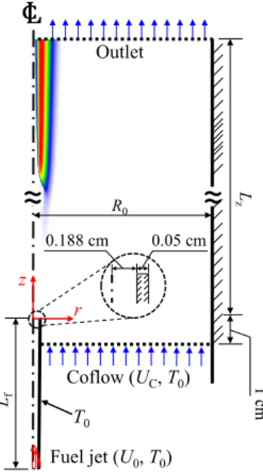
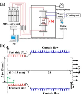
Detailed numerical simulations of laminar non-premixed flames in a counterflow burner are also performed in the 2-D axisymmetric coordinates for the radial, r−, and the axial, z−, directions. The purpose of the present study is twofold: (1) to understand the liftoff characteristics of self-igniting laminar lifted methane/hydrogen jet flames, in particular the reason for the occurrence of the decreasing behavior of HL with U0, and (2) to elucidate the flame stabilization and structural properties of the self-igniting laminar lifted jet flames by performing 2-D detailed numerical simulations for various inlet fuel jet conditions and hydrogen mass diffusion.
Overall characteristics of the lifted flames
Chemical kinetic mechanisms
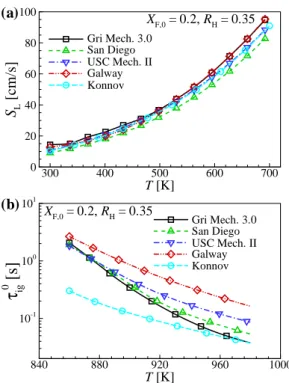
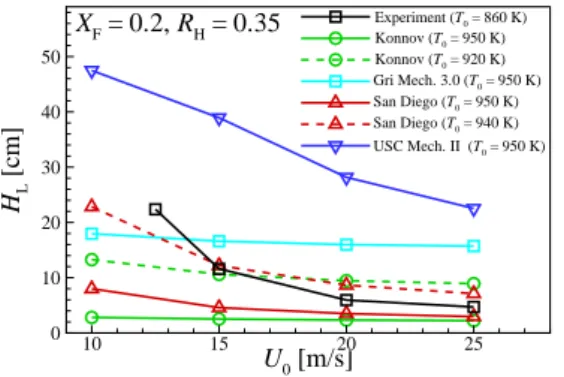
They hypothesized that this temperature discrepancy could be attributed to inaccuracies in the chemical kinetic mechanism/transport data and/or experimental measurements. HL values, the decreasing tendency of HL with U0 under the condition of LTHH remains the same for all chemical kinetic mechanisms with different T0.
Lifted jet flames under HTLH condition
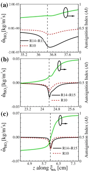
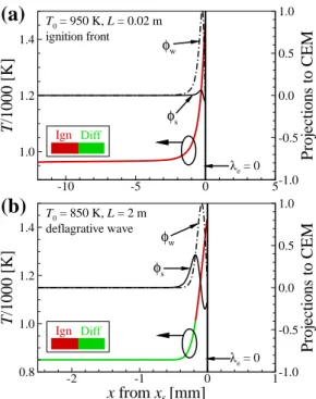
The figure shows that CH2O and H2O2 are dominant in front of the flame base, indicating that autoignition plays an important role in the stabilization of raised flames. To summarize the general characteristics of raised flames under HTLH conditions, the figure shows the changes in HL and (Tmax−T0)/Tig as a function of U0.
Lifted jet flames under LTHH condition
Note that under the LTHH condition, the flame base is defined as the most upstream point of YOH isoline. The chemical characterization of the lifted jet flames under the LTHH condition using CEMA will be addressed in Section 6.2.
Effect of hydrogen on the liftoff characteristics
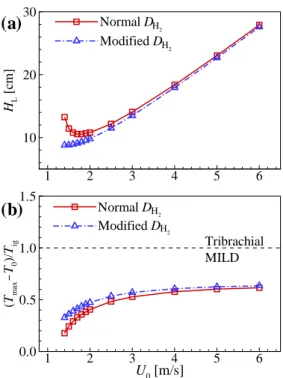
Effect of hydrogen mass diffusivity on H L
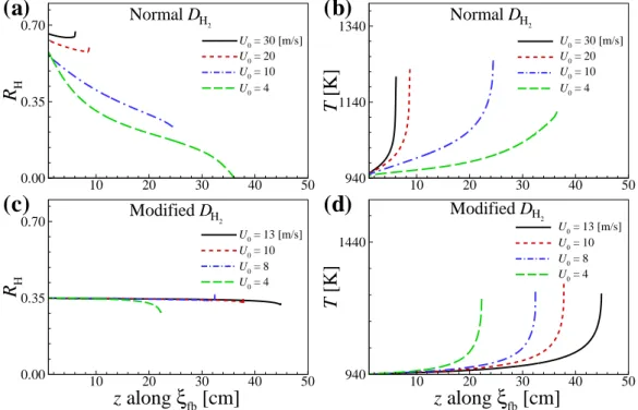
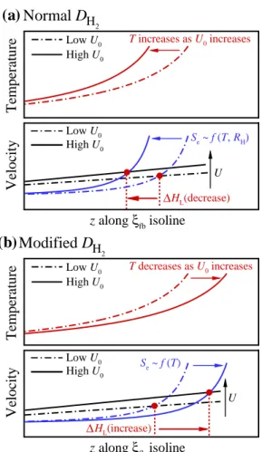
To further identify how large DH2 affects the mixture conditions upstream of the flame base and resulting ignition characteristics, we evaluate local hydrogen ratio, RH, along ξfb isoline for both normal and modified DH2 cases. However, for modified DH2 cases, the ignition characteristics do not change much for high U0, so that the profiles of local temperature and resulting Se are spatially elongated as in Fig.
Effect of hydrogen on the lifted flame stabilization
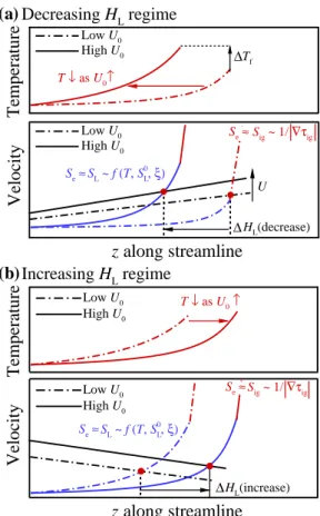
This implies that the base flame propagation speed of a raised flame, Se, becomes comparable to/significantly greater than the corresponding laminar flame speed, SL, if the raised flame is stabilized by the flame propagation/autoignition mode with self-ignition assistance. In the present study, SL upstream of the flame base is estimated from 1-D transient jet simulations as in .
Ignition characteristics: CEMA
U-shaped H L behavior
It is of interest to note that the mass fractions of the major species generated by DME pyrolysis (e.g., CH2O, CO, and H2) increase at the fuel tube outlet with decreasing U0, indicating the increased rate of DME pyrolysis within the fuel pipe. Here, HL is defined as the axial length from the fuel pipe outlet to the base of the flame.
Differential diffusion effect
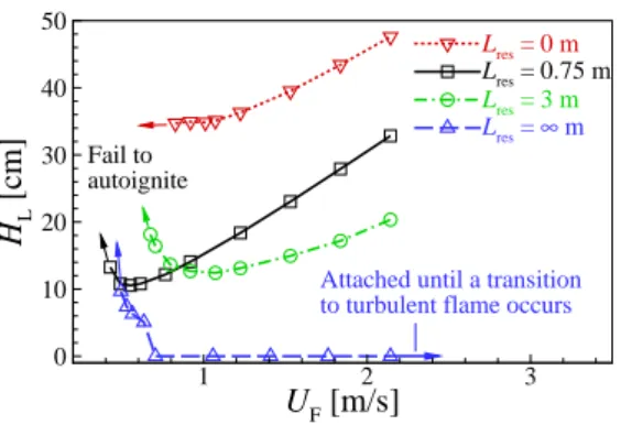
First, it is easily observed that the difference of HL between the two cases becomes significant for relatively small U0, while it becomes negligible for relatively large U0. Second, for relatively-small U0, (Tmax−T0)/Tig also shows a large inequality, which becomes negligible for relatively-largeU0.
Flame stabilization and autoignition characteristics
Stabilization mechanisms
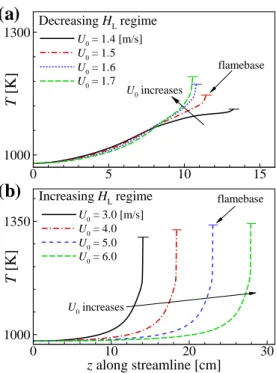
As a result, the local temperature upstream of the flame base decreases with decreasing U0 as shown in Fig. These results imply that the decreasing behavior of HL may occur by switching the stabilization mechanism from autoignition to autoignition-assisted flame propagation mode, independent of the flame. regime change.
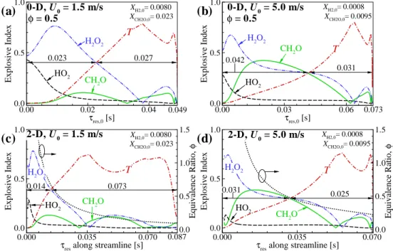
Ignition characteristics based on CEMA
However, the duration of the thermal ignition stage for the 2-D case with U0 = 1.5 m/s is much longer than that for the 2-D case with U0. For the increasing HL regime, however, the effect of differential diffusion on the overall ignition characteristics is not significant and therefore do not change much with U0.
Flame regime change by pyrolysis
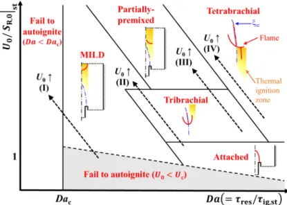
Based on the radial location of the flame base and (Tmax−T0)/Tig [96], we categorize DME. This regime represents the transition of the lifted DME jet flame from the MILD combustion to the tribrachial edge flame.
Overall characteristics
Autoignition-affected flame stabilization
Note that the flame base of the tribrachial edge flame deviates slightly from ξth isoline due to the existence of velocity gradient upstream of the tribrachial edge flame [111]. It is readily observed that Se/SR,0 ≈ 1 for the tribrachial edge flames, demonstrating that the stabilization mechanism of the current flames with.
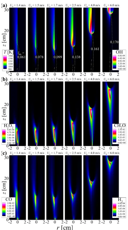
![Figure 5.1: Isocontours of (a) T [K] (left half) and Y OH (right half) and (b) Y CH 2 O (left half) and heat release rate [J/m 3 s] (right half) for autoignited laminar n-heptane jet flames for various fuel exit velocities, U 0 , with X F,0 = 0.02 and T 0](https://thumb-ap.123doks.com/thumbv2/123dokinfo/10487579.0/105.892.232.665.347.805/figure-isocontours-release-autoignited-laminar-heptane-various-velocities.webp)
Transition from tribrachial edge flame to MILD combustion
However, as the tribrachial edge flame approaches its stabilization position, the temperature rarely increases upstream of the flame base, while a significant temperature rise upstream of the flame base still exists for the MILD combustion condition. The contribution of autoignition to the flame stabilization is predominant for the MILD combustion mode, while it is marginal for the tribrachial edge flame mode.
![Figure 5.4: Temporal evolutions of T [K] (left half) and heat release rate [J/m 3 s] (right half) for autoignited laminar lifted n-heptane jet flames with (a) U 0 = 4.5 m/s and (b) U 0 = 8 m/s](https://thumb-ap.123doks.com/thumbv2/123dokinfo/10487579.0/109.892.235.662.135.656/figure-temporal-evolutions-release-autoignited-laminar-lifted-heptane.webp)
Ignition characteristics: CEMA
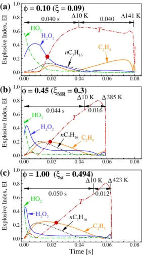
First, its relative importance of n-heptane for CEM is lower than for the other blends. To further understand the ignition characteristics of the mixtures, the temporal evolutions of PIs of important reactions are shown in Fig.
There appears to be a significant heat release upstream of the flame base, demonstrating the contribution of auto-ignition to flame stabilization. Because the flame base of the tetrabrachial rim flame is in a radially outward position compared to that of the tribrachial rim flame, the variation in HL of the tetrabrachial rim flame is relatively small compared to that of the tribrachial rim flame, as shown in Figure 2.
![Figure 5.11: Isocontours of T [K] (left half) and heat release rate [J/m 3 s] (right half) for autoignited laminar lifted n-heptane jet flames for various U 0 with T 0 = 1050 K](https://thumb-ap.123doks.com/thumbv2/123dokinfo/10487579.0/122.892.278.621.124.436/figure-isocontours-release-autoignited-laminar-lifted-heptane-various.webp)
Flame regime diagram
At relatively low U0, the elevated flame stabilizes as a tribrachial edge flame with a negligible temperature increase upward from the flame base. On the other hand, autoignition has been shown to play an important role in the flame stabilization of a raised flame with Tc = 1100 K (case Ig) [34].
Overall flame structure
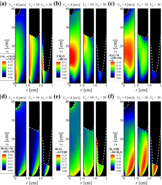
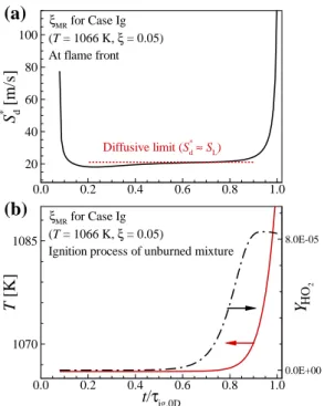
On the other hand, the isocontours of q˙ and YHO2 upstream of the flame base show different features depending on the case. Similar to the characteristics of q, the formation of ˙ YHO2 occurs further upstream of the flame base for case Ig (see Figure 6.3d).

Flamebase dynamics
The temporal evolution of T and YHO2 further upstream from the combustion wave is also shown in the figure. It is also interesting to note that for the Ig case, the size of the conditional mean Se/SL at moderate χ (i.e. s) is approximately unity, similar to the other cases.
Ignition dynamics upstream of turbulent lifted flames
For case Ig, α shows a local firing mode with |α| < 1 along fuel-lean mixtures upstream of the flame base, as expected [34]. However, for case H, the characteristics upstream of the flame base are similar even though the Tc slightly exceeds the auto-ignition limit.
Ignition dynamics within a rolled-up vortex
Basic concept
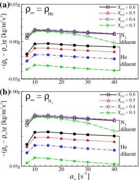
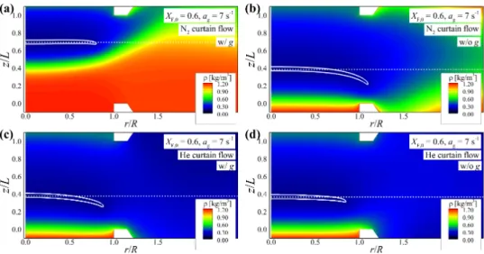
Since the non-premixed flames in the present counterflow configuration are surrounded by a curtain flow, the global driving force acting on the non-premixed counterflow flame can be adjusted by varying the curtain flow density. Also note that in the present study, ρ∞ can be considered as the curtain flux density (i.e. ρHe or ρN2 at 1 atm and 300 K).
Experimental and numerical results
For the cases of N2 curtain flow, the axial flame location changes significantly depending on gravity, which is consistent with the experimental results shown in Fig. However, for the cases of He curtain flow, the flame location rarely changes with gravity, suggesting that the curtain flow can effectively suppress the effect of buoyancy on the flame.
Flame stabilization and extinction
- Flame stabilization at low strain rates
- Flame stabilization: numerical results
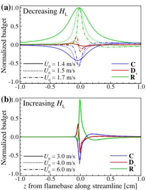
- Flame stabilization: transport budget analysis
- Flame extinction dynamics
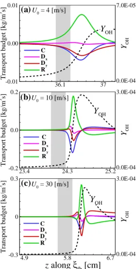
The characteristics of the flame edge structure can be classified into three distinct regimes: (I) the outward propagating bibrachial edge flame regime, where Se and Se+Ue,n are both positive; (II) an outward propagating monobrachial edge flame regime where Se is negative and Se+Ue,n is still positive; (III) receding monobrachial marginal flame. To further investigate the flame stabilization mechanism of the edge flame in a counterflow burner, we perform an analysis of the transport budget along the ξe isoline.
![Figure 7.5: Experimental and numerical critical inert gas mole fraction for extinction of counterflow nonpremixed flames of CH 4 /He versus air in He curtain flow and CH 4 /N 2 versus air [10, 11] without curtain flow as a function of a g .](https://thumb-ap.123doks.com/thumbv2/123dokinfo/10487579.0/163.892.304.586.128.317/experimental-numerical-critical-fraction-extinction-counterflow-nonpremixed-function.webp)
Future work
Chen, “Direct numerical simulations of self-ignition in stratified dimethyl ether (DME)/air turbulent mixtures,” Combust. Yoo, “A numerical study of the pyrolysis effect on self-igniting laminar raised dimethyl ether jet flames in heated coflow air,” Combust.
![Figure 1.3: Heat release rate [J/m 3 s] isocontours for (a) laminar lifted jet flame from [1]](https://thumb-ap.123doks.com/thumbv2/123dokinfo/10487579.0/33.892.297.585.126.425/figure-heat-release-rate-isocontours-laminar-lifted-flame.webp)