Introduction
Background
Carbon Fiber Reinforced Plastic (CFRP) has extremely good strength and light material, which contains carbon fibers and resin. However, CFRP is somewhat difficult to use for industry because it is anisotropic and inhomogeneous different from the physical properties of the metal [4, 5]. Since there are many defects such as delamination and tool wear during the machining of CFRP composites, optimization of machining is essential to improve productivity.
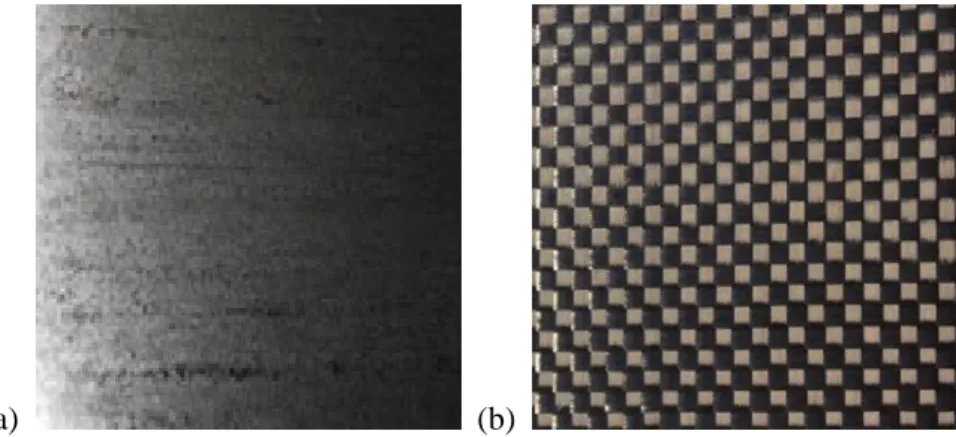
There are three types of CFRP as Uni-direction (UD) CFRP, Multi-direction (MD) CFRP, and Fabric CFRP, depending on methods of manufacture.
Research objectives and approach
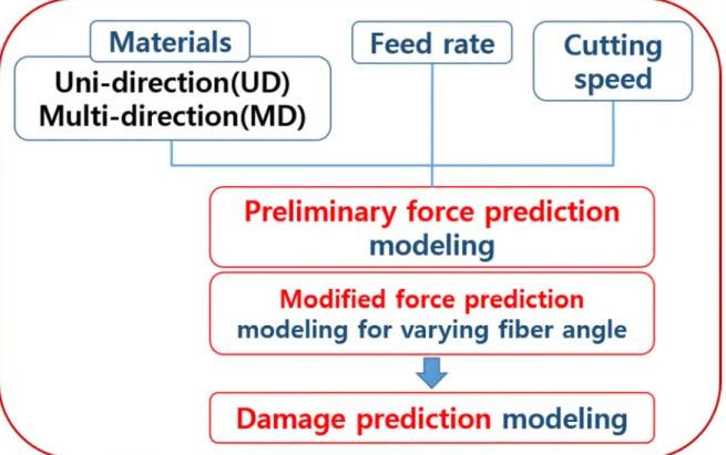
In addition, depending on parameters such as material properties, feed and cutting speed, force and machinability are affected. The objective of this research is to develop theoretical and numerical predictive models for the analysis of cutting forces in carbon fiber reinforced plastic (CFRP) processing and to experiment with CFRP orthogonal processing to analyze the characteristics of composite materials. The force prediction model along all fiber orientations can be used to predict the damage zone in CFRP processing.
According to preliminary research, it can be assumed that a delamination prediction model will be developed, including machining parameters such as feed speed and cutting speed, as shown in Figure 1-3.
Dissertation organization
The machinability of CFRP machining is related to the chip formation along the fiber orientation [31–34]. It is also assumed that this model is reasonable in the range of fiber orientation above 90°. In this condition, it is possible to assume the shear angle is equal to the fiber orientation.
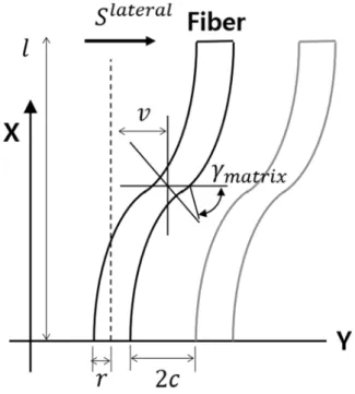
In these equations, and represent the indentation forces in the direction perpendicular to the fiber orientation. After applying boundary conditions in the range of fiber orientation less than 90°, the fiber deflection can be represented as (3-23). In the range of fiber orientation greater than 90°, the fiber deflection can be represented as (3-24).
4-11 (a), the thrust force is greater than the cutting force throughout the range of fiber orientation in high-speed cutting. This is the reason for poor machinability at low processing speeds, especially in the range of fiber orientation above 90°. We perform UD CFRP orthogonal cutting to identify the change in cutting forces with respect to fiber orientation.
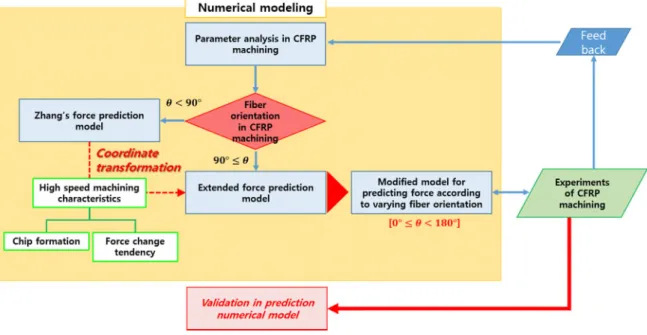
High prediction reliability of this damage prediction model can be seen in the condition of fiber orientation from 130° to 150°. There is a preliminary force prediction model and force prediction model according to varying fiber orientation. Force prediction model according to varying fiber orientation is extended from Zhang's CFRP force model [8].
The strength prediction model according to different fiber orientation has a similar trend to the experimental results. In conclusion, we have to consider the poor processing in the fiber orientation range above 90°. Defects occur intensively in the fiber orientation range above 90° at high feed rates.
Literature review
Mechanism of Carbon Fiber Reinforced Plastics machining
Characteristics of Carbon Fiber Reinforced Plastics machining
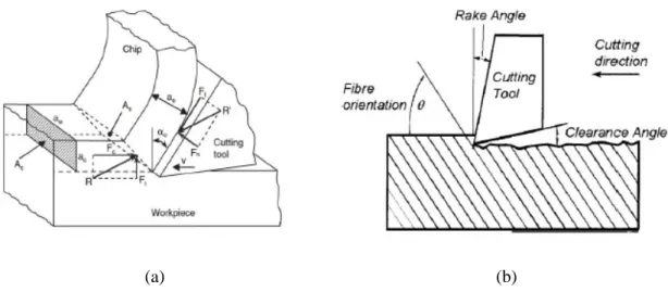
- Cutting forces in CFRP orthogonal machining
- Fiber orientation in CFRP orthogonal machining
- Chip formation in CFRP orthogonal machining
- Delamination in CFRP orthogonal machining
Numerical solutions to predict force in CFRP machining
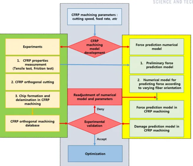
In this study, identifying CFRP orthogonal cutting is important because it can show force change along fiber orientation based on feed rate and cutting speed. It has many advantages: the short time required when simulating, and it can be identified by the cutting mechanism. Experimental numerical model has advantages of high accuracy compared to other methods with experimental parameters.
However, it needs preliminary experimental results and it has possibility to get different results depending on conditions. Finally, finite element method (FEM) is good for identifying CFRP cutting process in CFRP orthogonal machining. It can show the predicted failure modes identified for different fiber orientation angles by (Abena et al.
Its limitation is sometimes too much time required and different results depending on the computer. It is inevitable to verify these numerical methods with CFRP processing results such as shear force and thrust force. Orthogonal processing of CFRP is representatively the most effective for determining the relationship between cutting forces and fiber orientation angle.
These numerical force prediction models are important to define the characteristics of CFRP machining and to optimize the machinability of each machining parameter, such as feed rate and depth of cut, in CFRP machining. Thus, we attempt to establish a theoretical model that predicts force in the range of all fiber orientations from 0° to 90°.
Flow of research about theoretical solution to predict force and delamination in CFRP
This preliminary force prediction model can contribute to predict cutting forces in terms of the fiber orientation over 90° defined by the original fiber angle definition. So, the following model of Zhang's model [8] is selected to develop a continuous force prediction model along all the fiber orientation angles. Damage prediction model can also be proposed by applying force prediction model according to varying fiber orientation including machining parameters.
We observe internal defects such as delamination along the fiber orientation using X-ray CT.
![Fig. 2-9 Cross section of specimens in CFRP cutting; (a) fiber angle 90° , (b) 0° [35]](https://thumb-ap.123doks.com/thumbv2/123dokinfo/10524678.0/25.892.128.768.210.358/fig-cross-section-specimens-cfrp-cutting-fiber-angle.webp)
Numerical modeling
Numerical model for predicting force
- Preliminary model for predicting force
- Numerical model for predicting force according to varying fiber orientation
- Region 1 - Chipping
- Region 2 - Pressing
- Region 3 - Bouncing
- The total cutting forces
This research can extend this model to model along the entire fiber orientation range, 0° ≤ < 180°. In these equations, and are the shear force and thrust force, respectively, is the shear force along the fiber orientation, is the area of the undeformed chip area of the composite, is the friction angle of the composite, and denotes the tool rake angle. In these equations, and are the shear force and thrust force, respectively, is the shear force along the fiber orientation, is the area of the undeformed fiber chip area, is the undeformed epoxy chip area, is the fiber friction angle, is the friction angle of the epoxy, and denotes the rob angle.
In the preliminary model for strength prediction, there are some restrictions that only apply to the fiber orientation, > 90° and the discontinuous model. This research can extend Zhang's model to model depending on the whole range of fiber orientation, 0° ≤ < 180°. We consider Region 2 to be the most effective region because the fragmentation in Region 1 is simply dust type.
In these equations, and the shear force and the thrust force are respectively in region 1, the shear strength is along the fiber orientation, the shear strength is in the direction normal to fiber orientation. In these equations, and are the cutting force and the thrust force respectively in Region 2, ( )∗ in which, ( ) is a factor related to the fiber orientation. In these equations, and the shear force and the thrust force are respectively in Region 3, the effective modulus of the materials is in Region 3.
The sum of the cutting forces and the pushing forces is the total force. In these equations (3-12) and (3-13), the total cutting force and total thrust force are, respectively, at fiber orientation < 90°.
Numerical model for predicting damage
This cutting force is changed along the fiber orientation because deformation mechanism changes in each condition. To understand definite cutting mechanism flow of force change, force prediction model according to varying fiber orientation is essential. Experimental validation of numerical model for predicting strength and damage according to varying fiber orientation.
But cutting force is over the thrust force in fiber orientation over 90° in low speed cutting. Fiber bending in the range of fiber orientation over 90° occurs more critically in low speed machining conditions. In general, it is aimed to develop modified force prediction model according to varying fiber orientation and apply it in damage prediction model.
This damage prediction model can help to predict defects such as delamination in terms of the fiber orientation defined by the initial fiber angle definition. In the range of fiber orientation from 90° to 180°, it starts to make defects inside the UD CFRP blank. This damage prediction model can help predict defects such as delamination along the entire fiber orientation from 0° to 180° defined by the original fiber angle definition.
In Section 3, we develop numerical models to predict cutting forces and defects such as delamination along the fiber orientation. A similar cutting mechanism is used in the modified model along the entire fiber orientation from 0° to 180°.
Experimental validation
Experimental validation of preliminary model for predicting force
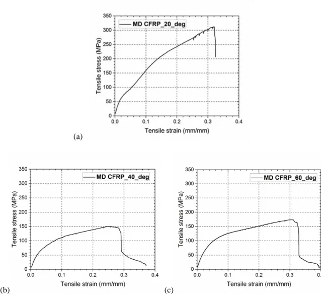
- MD CFRP property test
- Tensile test
- Friction test
- Experimental setup
- Comparison between experimental and analytical results
- Summary
- Experimental set
- Comparison between experimental and analytical results
- Summary
We can conclude that fiber bending in the fiber orientation range above 90° occurs more critically under low speed processing conditions. This result can support that the shear force is over the thrust force in fiber orientation above 90° in low speed cutting.
Experimental validation of modified model for predicting damage
- Experimental setup
- Comparison between experimental and analytical results
- Summary
Conclusions
Summary
In this study, we attempt to develop numerical solutions to predict the shear forces and damage along the fiber orientation under any machining condition in CFRP orthogonal shear. From this strength prediction model, the damage prediction model can be suggested by referring to Jahrom's damage prediction model [28]. First, the preliminary force prediction model can be seen that the cutting force and thrust force increase with the increase of feed speed similar to the experimental results.
This developed model is more accurate than Bhatnagar's model over a wider area under feed rate conditions of 0.21 mm/rev. The reason is that the epoxy region included in the preliminary strength prediction model rises to a wider area. However, in the range of fiber orientation from 90° to 180°, it starts to make defects inside the UD CFRP workpiece.
Conclusions and contributions
Future work
Mk, N.K., et al., Tool wear and surface roughness in milling carbon fiber reinforced plastic using cooled air. Journal of Asian Scientific Research, 2012. Bhatnagar, N., et al., On the machining of fiber reinforced plastic (FRP) composite laminates. International Journal of Machine Tools and Manufacture p. Turchetta, Cutting forces when milling carbon fiber reinforced plastics. International Journal of Manufacturing Engineering, 2014.2014.
Travel, Damage and Dimensional Precision on Milling of Carbon Fiber Reinforced Plastics Using Design Experiments. Journal of Materials Processing Technology p. Chen, W.-C., Some experimental investigations in the drilling of carbon fiber reinforced plastic (CFRP) composite laminates. International Journal of Machine Tools and. Rahman, M., et al., Machinability study of carbon fiber reinforced composite. Journal of Materials Processing Technology, 1999.89: p.
Calzada, K.A., et al., Modeling and interpretation of fiber orientation-based failure mechanisms in the machining of carbon fiber reinforced polymer composites. Journal of Manufacturing Processes p. Santiuste, C., et al., Delamination prediction in orthogonal machining of carbon long fiber reinforced polymer composites. Journal of Reinforced Plastics and Composites, 2012. Krishnan, An analytical method for predicting the damage zone in orthogonal machining of unidirectional composites. Journal of Composite Materials, 2014.
Hocheng, Chip formation model of cutting fiber-reinforced plastic perpendicular to fiber axis. Journal of Manufacturing Science and Engineering, 1998. Namgung, Machinability of carbon fiber-epoxy composite materials in turning. Journal of Materials Processing Technology, 1992.
Acknowledgement
![Fig. 1-1 Global demand for carbon fiber from 2008 to 2020 [Mark Holmes et al. (2014), materialstoday]](https://thumb-ap.123doks.com/thumbv2/123dokinfo/10524678.0/13.892.147.773.465.890/fig-global-demand-carbon-fiber-mark-holmes-materialstoday.webp)
![Fig. 2-1 The XXsys carbon fiber jacket site filament winding technique (USA) [9]](https://thumb-ap.123doks.com/thumbv2/123dokinfo/10524678.0/18.892.236.657.778.1058/fig-xxsys-carbon-fiber-jacket-filament-winding-technique.webp)
![Fig. 2-7 Chip morphology SEM photos of carbon fiber with orientation angles along the fiber direction; (a) 0° ≤ < 90° fiber orientation, (b) 90° ≤ < 180° fiber orientation [25]](https://thumb-ap.123doks.com/thumbv2/123dokinfo/10524678.0/22.892.131.762.686.1022/morphology-photos-carbon-orientation-angles-direction-orientation-orientation.webp)
![Fig. 2-8 Comparison of experimental and analytical results for predicting damage [28]](https://thumb-ap.123doks.com/thumbv2/123dokinfo/10524678.0/23.892.148.750.525.916/fig-comparison-experimental-analytical-results-predicting-damage-28.webp)
![Fig. 2-11 Cross section of specimens in CFRP cutting; (a) fiber angle 90° , (b) 180° [37]](https://thumb-ap.123doks.com/thumbv2/123dokinfo/10524678.0/26.892.155.743.361.579/fig-cross-section-specimens-cfrp-cutting-fiber-angle.webp)
![Fig. 2-13 The cutting diagram in CFRP orthogonal machining; (a) Region 1, (b) Region 2, and (c) Region 3 [8]](https://thumb-ap.123doks.com/thumbv2/123dokinfo/10524678.0/28.892.157.747.124.499/cutting-diagram-cfrp-orthogonal-machining-region-region-region.webp)
