Finally, an investigation was conducted on the delamination of CFRP composite laminates during the drilling process. Von miss stress contour of the output surface of composite laminates with a) backing plate and b) without backing plate.
Introduction
Research background and motivation
To avoid the delamination and make high quality hole, understanding of drilling mechanism and prediction of optimal process parameters for drilling process is essential. However, understanding of mechanism and observation of behavior of workpiece during the process was not able.
Research objectives
Outline of This Work
Literature reviews
Machining characteristics of CFRP materials
- Carbon Fiber Reinforced Polymer (CFRP)
- Experimental analysis on CFRP drilling
- Assessment of delamination
New methods have been proposed by researchers to compensate for the disadvantages of the conventional method. General method of delamination measurement was carried out by using optical microscope which was the most economical and easiest method.
Analytical modeling in composite material drilling
98 The rim region was considered a very small region of orthogonal cutting operations for model development. The inclusion of more geometric parameters of the drill bit geometry can further increase the applicability of the model for predicting CFRP machining.
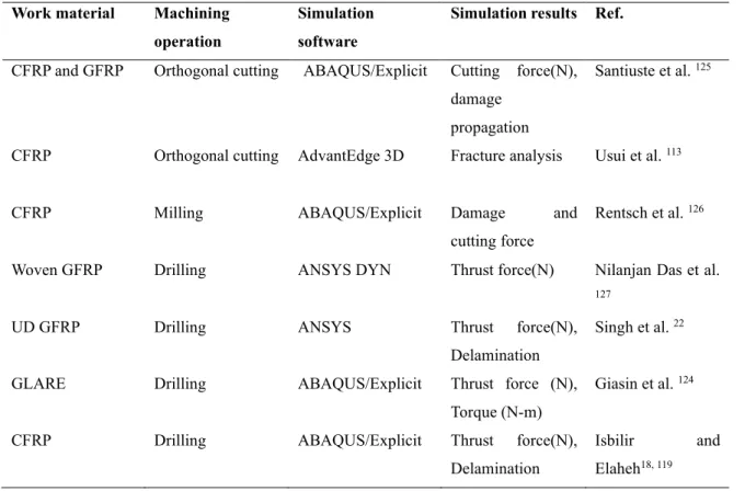
Numerical modeling in composite material drilling
Al-wandi et al. conducted the finite element and experimental investigation to evaluate the delamination occurred during the CFRP drilling process by presenting an equivalent modified delamination factor 123. Wu et al. carried out the FE model to predict the drilling force and torque using the Deform-3D finite element simulation software.
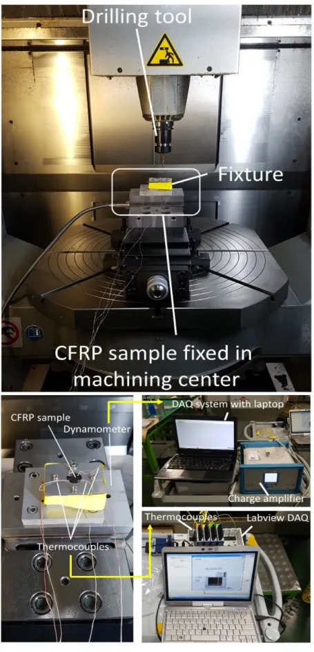
Experimental investigations on CFRP drilling process
Introduction
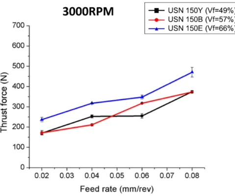
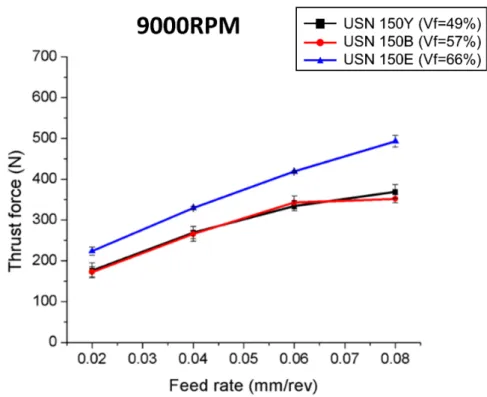
Investigation on thrust force according to the fiber volume fraction
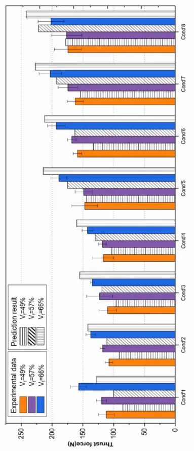
The effect of increasing volume fraction on peak thrust force is shown in Figure 3-5. This deviation may have been due to the non-linear change in material properties such as strength and modulus when the fiber volume fraction increased from 50%.
Investigation on delamination
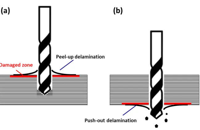
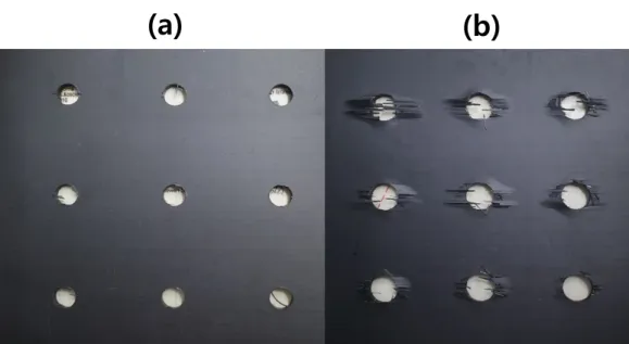
Delamination due to the drilling process occurs on both sides of the entry and exit surfaces of CFRP composite material. The delamination factor (Df) in this work indicates the ratio between the delaminated area and the drilled hole area, which is one of the most commonly applied assessment methods in the previous studies. As shown in Figure 3-12, the delamination generated in the exit surface of CFRP was limited to the diameter of the hole of the back plate with which the fixture was equipped.
Delamination propagates according to the fiber orientation of the unidirectional CFRP, and the degree of delamination gradually increases as the feed increases. Delamination factor of the non-support plate and conditions of the support plate according to the input. Delamination factor (mm/rev). Non-backing plate) Delamination factor. Optical observation of the drilled hole has a limitation that cannot be quantified due to the delaminated surface of composite laminates.
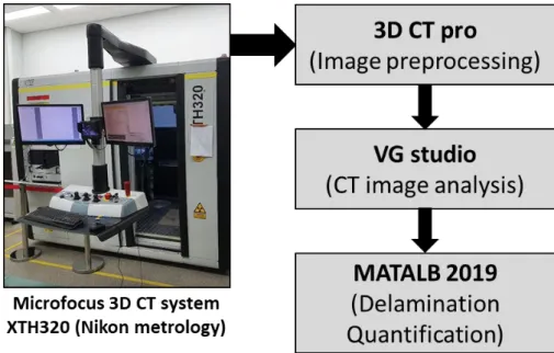
For the quantification of the delamination factor, CT images were acquired as shown in Figure 3-12.
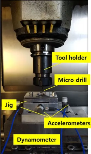
Investigation on drilling process of micro drill bit
- Machinability of micro drilling process according to cutting condition
- Delamination of micro drilling process
- Investigation on vibration assisted drilling
The workpiece materials used in the micro-drilling experiments are 3 types of CFRP composite laminates according to the pre-preg and layer stacking types. CFRP yield surface by pin speed and wear (diamond coated, uncoated). The machined bore shows less uncut fiber as well as lower warp ratio according to spindle speed.
CFRP exit surface according to spindle speed and process types (normal, pick drilling). Delamination factor according to spindle speed and 15,000 rpm) and drill types (normal and pick drills). Delamination factors depending on the spindle speed with a feed rate of (a) 10 mm/min, (b) 30 mm/min and (c) 50 mm/min using a 1 mm diameter drill.
Delamination factors according to the spindle speed with feed rate of (a) 10mm/min, (b) 30mm/min, and (c) 50mm/min using 0.5mm diameter drill bit.
Conclusions
Analytical modeling for thrust force during CFRP drilling process
Introduction
Analytical modelling
- Forces on the chisel edge
- Forces on the cutting lips
- Thermo-physical modeling of CFRP drilling process
- Fluctuation modeling for drilling process
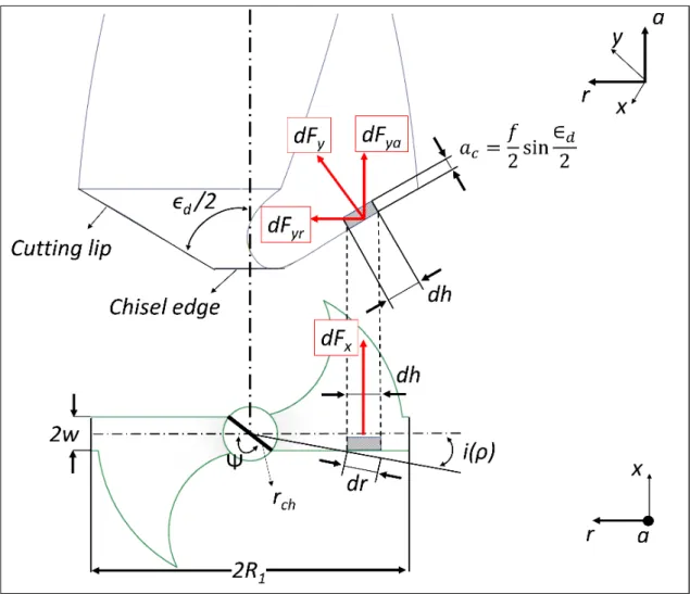
The elemental force given in Equation 1) can be integrated over the entire region of the chisel edge geometry to find the total thrust force as described by Eq. As shown in Figure 4, the force generated by the small cutting edge, dh, of the drill mouth can be separated into two components: dFx represents the perpendicular cutting force and dFy represents the perpendicular thrust force. When the cutting edge of the drill mouth is small, the mouth can be more simply described as several rectangular cutting edges, where each edge has different cutting parameters.
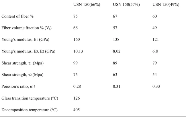
The radius of the cutting edge starts at the edge radius of the chisel and increases to its maximum value R1, at which the cutting edge is fully involved in a drilling operation. Vf is the fiber volume fraction of the CFRP composite, and Tg and Td are the glass transition and decomposition temperatures, respectively. The temperature of the drilling process was measured experimentally and the temperature behaviors were incorporated into the empirical model so that the mechanical properties of the composite laminates could be accurately modeled.
It was assumed that the minimum compressive force was generated when the chisel edge interacted with the resin in the CFRP composite and the angle between the cutting lip and the fiber was θ0 = 90°.
Validation of analytical model
- Thrust force curve for full stages of drilling process
- Thrust force fluctuation
Experimental and predictive result of thrust force under different drilling conditions and fiber volume fractions. 4-1 shows the thrust force values at the specific time which are divided into 12 points as shown in Fig. It appears that the reduction in thrust is mainly due to the softening effect from the heat from the drilling process.
The reduction in thrust force during phase 3 showed a difference between the experimental and predicted results; the general trend of the curve showed good agreement. The predicted thrust force curves in Figure 4-10(b,c) also showed good agreement that do not deviate significantly from the experimental thrust force curves. In the validation results, the boundary lines showing the maximum and minimum predicted thrust force of the model show a similar trend to the boundary of the thrust force results obtained from the experiment.
At the elapsed time of 200 msec from the starting point, the maximum and minimum thrust force of the experiment results are 38.4N and 13.7N, respectively, in Figure 4-11(a).
Conclusions
Numerical modeling of CFRP drilling process
Introduction
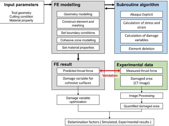
FE model development
- Setup of FE model
- Geometry, Mesh, Elements, and Boundary conditions
The drill FE model consisted of drill, workpiece, and fixture as shown in Figure 5-2(b). Layers in the FE model were stacked in order of s, and contiguous surfaces with a thickness of 0.010 mm were implemented between the layer interfaces. The dimensions of the drill used in the FE model are described in table 5-1.
FE model setup for (a) Drill head (b) Isometric view (c) Radial view with dimensions (d) Boundary condition with half-section view (e) Stacking sequence of layers with cohesive surfaces. Gnc, Gsc, and Gtcrepresent the critical values of fracture energies required to initiate failure in the normal and first or second shear directions, respectively. Section A in the figure implies linear elastic behavior from the normal and both shear stiffnesses (Kn, Ks and Kt), and the curve increases continuously until it reaches the peak point.
In section 3 damage development occurs, where the material stiffness deteriorates once the initiation criterion is reached as in section 2.
Results and Discussion
- FE simulation results
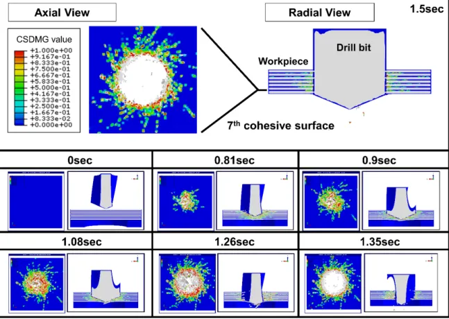
For the evaluation of delamination factor of material, the damaged area of cohesive surface at the end of the process was assessed as the delaminated area.
Validation of Finite Element model
The FE model was developed under both conditions with the support plate and without a support plate. The delamination factors were concentrated around 1.4 and increased slightly depending on the feeding conditions while the support plate was attached to the workpiece. However, the delamination factors without support plate were gradually increased as the feed rate increased during the experiment.
For the FE results with back up plate, we can see that the minimum damage value above 0.8 meets the delamination factor from the experiment. Delamination factor results of FE simulation according to the minimum damage criterion value with backing plate at cutting condition of a) 9000 RPM and 540 mm/min by federate and b). Delamination factor results of FE simulation according to the minimum damage criterion value without back-up plate at cutting condition of a) 9000 RPM and 540 mm/min by federate and b).
The delamination factor is the result of the feed and damage values in the presence of a) backing plate and b) without backing plate.
Conclusions
Concluding Remarks
Overall Conclusions
93. The entire drilling process was calculated by taking into account the thermophysical properties of the CFRP composite materials and was validated in the time domain. The modeled data captured trends with the experimental results at specific time points across all stages. Scans of the output surface of the composite laminate were processed by MATLAB to obtain Df.
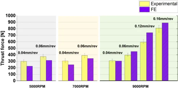
An FE model of CFRP composite laminate properties was developed in Abaqus/Explicit software using a user-defined material subroutine (VUMAT) and cohesive surfaces. The thrust forces calculated by the FE model were compared with the experimental results to validate the performance of the model for the assessment of delamination. In the case of, drilling with backing plate, applicable damage value was 0.9 and average error of simulation model was 5.32%.
In the non-backup plate condition, the correct damage value was 0.8 and the average error of the simulation model was 9.17%.
Path Forward
Chen, W.-C., Some experimental studies in drilling carbon fiber reinforced plastic (CFRP) composite laminates. Knoblauch, V.; Schneider, G., A comparative study of tool wear and laminate damage in drilling carbon fiber reinforced polymers (CFRP). Wang, C.; Cheng, K.; Rakowski, R.; Greenwood, D.; Wale, J., Comparative studies of the effect of pilot drilling with application to high speed drilling of carbon fiber reinforced plastic (CFRP) composites.
F.; Luo, B., An efficient model for dynamic analysis of shear strength in CFRP/AL pile drilling. Meng, Q.; Zhang, K.; Cheng, H.; Liu, S.; Jiang, S., An analytical method for predicting thrust force fluctuation during drilling of unidirectional carbon fiber reinforced plastics. Zitoune, R.; Krishnaraj, V.; Collombet, F.; Le Roux, S., Experimental and numerical analysis on drilling of carbon fiber reinforced plastic and aluminum piles.
Brinksmeier, E.; Janssen, R., Drilling of multilayer composite materials consisting of carbon fiber reinforced plastic (CFRP), titanium and aluminum alloys.