Schematic illustration of healthcare sensor with a user interactive system for monitoring various bio-signals in human-machine interfaces. wearables for the healthcare system. right). Resistance change in TPU/GO composite film under strain according to different concentrations of GO (1wt%, 2wt% and 3wt%). Resistance change according to different thickness of TPU/rGO/IL composite film and effect of annealing time on strain insensitivity. a) Comparison of resistance change as affected by film thickness.
Repeated cycling test of TPU/rGO/IL composite film under strain for durability.
Electronic skin (E-skin)
The triboelectricity can be generated by motions of vertical contact, shear friction as shown in Figure 1.3d. By using these working mechanisms and combining dual transduction modes, the multifunctional e-skin can be fabricated by Figure 1.4.36 The upper film mimics a fast-adaptive reception in human skin by using piezoelectric sensing mode for dynamic stimuli and the bottom piezoresistive film is is used for static pressure sensing by mimicking a slowly adapting reception of human skin.
Microstructured e-skin
Piezoresistive pressure sensor
6 skin.59 Furthermore, using microstructure can solve the limitations of the sensor with planar structure such as crosstalk in the change of resistance by variation of internal distances between conductive fillers. Furthermore, to maximize the sensitivity of the piezoresistive sensor, the concentration of conductive fillers must be controlled near the percolation threshold, where the resistance of the composite suddenly changes.
Ionic sensor
Capacitive sensor for proximity
Challenge of electronic skin
Research goal
Deformation insensitivity also depends on the thickness and annealing temperature of TPU/rGO/IL films (Figure 3.7). Therefore, the initial resistance of the TPU/rGO/IL films decreases steadily as the annealing time increases, resulting in an increased change in resistance under load. In the conductive TPU/rGO/IL composite film, the distance between the GO sheets is reduced by compression under normal pressure.
In the non-contact state, the capacitance of TPU/rGO/IL films as electrodes is constant because the sensor is not dimensionally deformed. While the capacitance increases when the finger touches the SSIMP sensor and pressure is applied, resulting in a reduced distance between the TPU/rGO/IL films with a large change in dielectric dimensions. As the amount of stretch increases, the initial resistance of the sensor decreases slightly.
General schematic of the SSIMP sensor. a) Highly stretchable conductive composite film with voltage insensitivity based on ionic network. As the GO charge is increased, the change in current is also increased. a) Dependence of TPU layer with different structure on the pressure sensitivity (with planar, double planar, single microdome and interlocked microdome structure). The sensor with interlocked microdome insulating layer has the increased pressure sensitivity. Proximity detection in non-contact and contact. a) The capacitance changes when the hand is approached in non-contact, where the capacitance is reduced.
Experiments
Fabrication of SSIMP sensor
For the interlocked microdome structure of the sensor, TPU insulating layer with microdome pattern (Optimized thickness: 230 μm) was attached to each TPU/GO/IL film after O2 plasma (Tergeo, PIE Scientific) in the condition of 15W and 20s. To make a strong adhesion of TPU insulating layer under the stretch, annealing for 12min at 160°C with the weight (200g) was performed (Figure 2.1). Each TPU/GO/IL film with TPU insulation should be overlapped with the top side where micro domes on the surface of TPU insulating layer are together.
Based on this procedure, single and multichannel SSIMP sensor with diverse sizes were also formed.
Characterization
For the applications, the 6ⅹ6, 4ⅹ4, and 4ⅹ3 array multichannel sensors were respectively measured using both the semiconductor parameter analyzer (4200-SCS, Keithley) and the multichannel biosensor system (OT15-3010D, ONTEST).
Fabrication of multichannel array
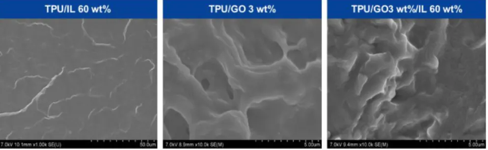
The surface of TPU/rGO/IL is smoother than TPU/rGO composite which has a 2D layer structure of GO sheets. In TPU/rGO/IL films, the conductive network of GO sheets is decoupled under stretching (tensile stress). As a result, TPU/rGO/IL films show an increased strain insensitivity (ΔR/R0 = 1.45, where R0 is the initial resistance of sensor and ΔR is the change in resistance) compared to TPU/IL and TPU/rGO- films (Figure 3.4b).
By adjusting the concentration of ionic liquid and GO, insensitivity to TPU/rGO/ deformations. One is the contact surface of the TPU/rGO/IL films, and the other is the interval between the TPU/rGO/IL films. Compared with the TPU/GO composite film, the TPU/rGO/IL film has a smoother surface because it forms an ionic network between the GO sheets. a) EDS data of the TPU/IL composite (60 wt.% ionic liquid to TPU polymer).
Schematic illustration of the strain insensitivity mechanism in conductive TPU/rGO/IL composite based on piezoresistive type and comparison with TPU/IL and TPU/GO composite films. In TPU/rGO/IL composite, IL plays a role as a conductive bridge between disconnected GO sheets under stretching. The change of resistance according to different IL concentrations in TPU/rGO/IL composite film, where the optimized concentration of IL is 60 wt% with respect to TPU polymer matrix.
Results and Discussion
Strain insensitivity of a conductive composite
Ionic liquid (IL) is completely dispersed in a free volume of the TPU films and makes ionic network which is the noncovalent association of cation-anion pairs ([EMIM]+[TFSI]-). These ions can bind with soft or hard segment of TPU polymer chain and some are partially integrated between the hard segment of TPU.68 Under the mechanical deformation, free ions that are not confined to TPU chain push out through viscoelastic deformation of TPU chain. . During the reduction of GO, the time of reduction is an important factor in determining its electrical conductivity.
When the IL concentration increases, the strain insensitivity also increases due to the conducting bridge effect of the ionic liquids (Figure 3.8).
Pressure sensing performance under the strain
29 maintained even under stretching indicating that our sensor can precisely detect the pressure independent of tensile stress. In addition, the resistance of the sensor is maintained even under bending (bending radii of 3 cm, 2 cm, 1 cm and 7.5 mm). The difference of initial resistance change under applied pressure of 30 kPa between flat and bent conditions at bend radii of 7.5 mm is only 0.317 (ΔR/R0, where R0 is the initial resistance on the flat condition and ΔR is the change in resistance between flat and bending state)(Figure 3.15b).
When the bending radius decreases, the contact area between TPU/rGO/IL films also decreases due to the curvature of a hemispherical object, causing the initial resistance to increase. However, under the applied pressure, smaller bend radius has lower resistance change than others due to smaller change in contact area. In addition, bending causes the interval between TPU/rGO/IL films to decrease through a fixing process, which slightly reduces the resistance change due to the relatively lower initial resistance.
Therefore, the change in current in the bend radius (r = 7.5 mm) is smaller compared to the planar condition, as shown in Figure 3.15b. That means the change of current is negligible under bending and we can detect the precise pressure even under the bending conditions.
Proximity sensing
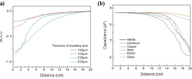
The graph shown in Figure 3.16c is a negative change in capacitance under repeated non-contact hand approach. Our sensor exhibits good proximity sensing performance compared to previous papers (ΔC/C0 = -0.82 at 2 mm of distance before contact, where C0 is the initial capacitance and ΔC is the change in capacitance with distance between the TPU/ rGO/IL films). Notably, the SSIMP sensor can also distinguish non-contact and contact change well from capacitance change (Figure 3.17).
Also, we performed the experiment to measure the capacitance change with different thicknesses of the TPU insulating layer and the adjacent materials. It is similar to the thickness above (230 μm) of the TPU insulating layer which is the optimized state of the TPU insulating layer in terms of pressure sensitivity (Figure 3.18a). In addition, to exploit the high sensitivity for proximity sensing, we investigated the variation of capacitance change by different materials.
The tested materials include metals, polymer and other dielectrics such as copper, aluminium, steel, PDMS and glass (Figure 3.18b and Figure 3.19). In addition, the human body has large change in capacitance due to greater shielding effect on the electric field. While the PDMS and glass have a lower capacitance change compared to others due to relatively lower conductivity and surface charge.
Multichannel array
As the finger moves closer to the sensor, the effective capacitance of the sensor is reduced by the edge effect and thus the total capacitance is reduced. When different shapes and weights of loads are applied, the sensor array can distinguish the compressed area and the extent of the applied pressure. The array of sensors can perceive the shape of the dough load and a subtle change in applied pressure caused by the uneven surface of the load in Figure 3.20 (c).
The matrix sensor can also detect the difference between the central and peripheral areas of an object, where the pressure is concentrated in the central area based on the color mapping image. It demonstrates that the SSIMP sensor array enables accurate detection of the location and magnitude of applied pressure. Due to the rough surface, which has a different amplitude of protrusion, each point receives unequal pressure.
So the intensity of the area pressed by the load is lower than the initial in the color mapping image. In the capacitive sensor mode, we can estimate a shape of the object as well as a distance between object and sensor using 6 ⅹ 6 multichannel sensor array. Furthermore, we can perceive an accurate shape and weight of the object by spatial pressure distribution and its size using the piezoresistive sensing mode.
When the TPU/GO film is stretched, the interval between the GO sheets increases and thus the resistance of the film also increases. Resistance variation with different concentrations of GO (1 wt%, 2 wt%, and 3 wt%) and IL (~100 wt%) under load to find the optimized condition for load insensitivity. a).
Conclusion