This document represents the security concerns of the AMI-SEC Task Force and provides guidance and security controls for organizations developing or implementing AMI solutions. The SG Security Working Group (WG) and the AMI-SEC Task Force (TF) would like to acknowledge the work of the lead authors, contributing authors, editors, reviewers, and supporting organizations. The Advanced Metering Infrastructure Security Task Force (AMI-SEC) was established in August 2007 under the International Utility Communications Architecture User Group (UCAIug) to develop consistent security guidelines for the initial AMI portion of the Smart Grid.
In response, the AMI-SEC leadership defined a project to accelerate and complement the work of the Task Force, referred to as ASAP.
P URPOSE
S COPE
A PPROACH
The security controls were selected based on their applicability to the components and messages of the AMI scenarios that were studied. Security service domains were used as a tool to further characterize these components with respect to additional security issues.
A UDIENCE
D ISCLAIMER /S TATUS
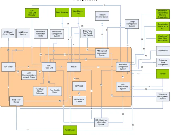
Although AMI systems will vary between gadgets in terms of technology choices and the features they intend to support, at a logical level there is much in common. From this analysis, we extracted a logical architecture (presented in Section 4.2) that summarizes the communications between the logical components. Finally, we used security domains (described in Section 4.4) to further characterize these components with respect to additional security aspects.
This shared understanding of the AMI domain, the components within the domain, and their communication patterns and security issues was used to select the requirements for each logical component.
U SE CASE AND SCENARIO ANALYSIS
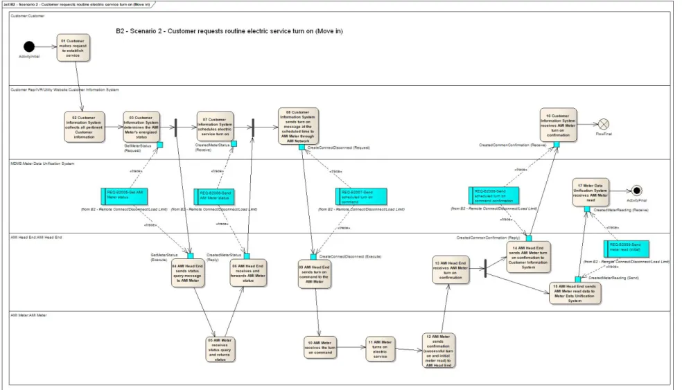
We began our analysis with a review of use cases and related detailed scenarios provided by the AMI Enterprise community (based on work SCE has contributed to the community). Given the scope of this security profile, we limited our attention to the use cases that describe AMI capabilities and business processes. Components: each swimlane shows a different entity involved in the business flow captured in the scenario's activity diagram.
For example, in scenario 9 of use case B1, a meter is shown that communicates with the MDMS without going through a head end.
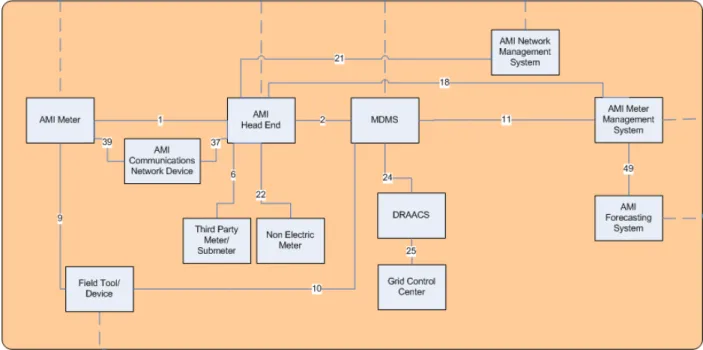
L OGICAL ARCHITECTURE
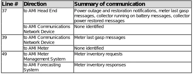
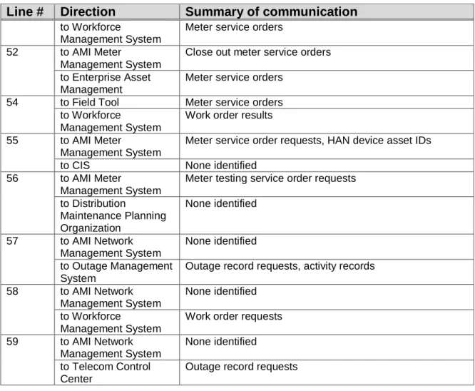
1 to AMI Meter Meter reading requests, on/off commands, pricing information, provisioning requests, firmware updates, prepayment information. Meter reading data, non-electrical meter events, customer energy data, customer 7 HAN equipment responses to AMI head unit Not identified. 15 to the AMI main unit Various commands (on-demand shutdown, scheduled on/off, load limit), requests for live meter status, electricity price data, meter provision requests, various messages (informational, prepaid service, price change) .
16 on AMI Meter Miscellaneous confirmations (event notifications, event start/end, HAN communication), prepayment status receipt.
C OMPONENT DEFINITIONS
- AMI Communications Network Device
- AMI Forecasting System
- AMI Head End
- AMI Meter
- AMI Meter Management System
- AMI Network Management System
- Demand Response Analysis and Control System (DRAACS)
- Field Tool/Device
- Grid Control Center
- Meter Data Management System (MDMS)
- Non-Electric Meter
- Third Party Meter/Submeter
What is the difference between AMI Meter Management System and AMI Network Management System. AMI meters are placed on equipment located in the field (eg, at the side of a customer's home) and as such have limited physical protection. Like AMI Meters, Non-Electrical Meters are field deployed and as such have limited physical protection.
Third party Meters/Submeters are field deployed and as such have limited physical protection.
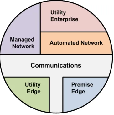
AMI S ECURITY S ERVICE D OMAINS
Delineation of Domains
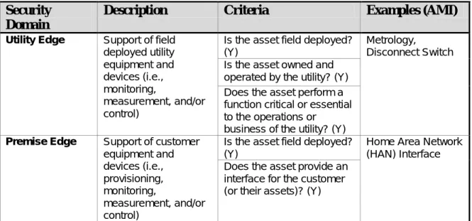
Each of the AMI security service domains represents a comprehensive set of concerns, including (but not limited to) ownership, control, physical access, logical access, information sensitivity, and business functionality. Physical assets are distributed throughout the drawing and are not supposed to move or change domain. The drawing assumes that other utility applications outside of AMI such as outage management and customer information will connect through the utility domain.
Field applications such as the Home Area Network or other utility meters (ie, gas or water) will be connected through the Premise Edge or Utility Edge domain.
Domain Characteristics
Does the asset control the business operations (i.e., not the communication behavior) of assets or provide the business processing of data of assets in the Utility Edge domain. Does the asset provide an interface for assets in the Utility Enterprise domain to access assets in the Utility Edge or Premise Edge domain. Provides the asset with a single logical interface point to assets in the Utility Enterprise domain for operating data from assets in the Utility Edge or Premise Edge domain.
Does the asset provide an interface for monitoring or manipulating functions performed by assets in the automated network or communication domains.
Domain Analysis – Significance, Relevance, and Influence
The AMI system and communications protection policy should be included as part of the general information security policy for the organization. The organization shall: (i) establish usage restrictions and implementation guidelines for Voice over Internet Protocol (VOIP) technology based on the potential to cause damage to the information system if used intentionally; and (ii) authorize, monitor and restrict the use of VOIP within the AMI system. The organization will secure backups of critical software, applications and data for all components of the AMI system.
The organization will authorize, manage and monitor maintenance and diagnostic activities performed remotely on all AMI system components. The organization shall test the continuity of operations plan for the AMI system at least annually, using The organization must identify, report and correct AMI system weaknesses (according to organizational, legal and/or regulatory policies).
The use of automated vulnerability remediation procedures shall not impair the operational performance of the AMI system; The organization must reassess the integrity of the software, firmware and data by conducting AMI System Integrity Checks; The use of integrity checking applications must not adversely affect the operational performance of the AMI system.
The organization will implement security measures to limit the entry of information into the AMI system to authorized personnel only. The design of the AMI system component must consider all valid inputs during its operation. The organization must identify authorized users of the AMI system and specify access rights and privileges; i.e. access control list.
Any delay caused by the use of cryptography shall not impair the operational performance of the AMI system.
A UDIT AND A CCOUNTABILITY
General quality assurance audits of the setup and operation of the AMI system verifying compliance with the organization's security plan;. Audits of operational events encountered by the AMI system when the system is operating outside of its normal operating parameters. Operational event audits are initiated by the organization's corrective action process when the AMI system is operating outside of its normal operating parameters.
The AMI system issues a warning when the specified audit data storage volume reaches the organization-defined percentage of the maximum audit data storage capacity;. The AMI system provides a real-time alert when the following organization-defined audit failure events occur. All system and AMI components must provide timestamps for use in generating audit data.
Understand the AMI system to be audited and be personally familiar with the systems and operational practices; As a general practice, system audits determine the compliance of the AMI system with the organization's security plan. Auditing and log management tools should be used with care when maintaining and demonstrating the integrity of an AMI system from installation through the system lifecycle.
The AMI system and its components will continue to function during and after a cybersecurity scan. For these reasons, any audit and testing of the AMI system will be strictly controlled.
S URVIVABILITY
For these reasons, auditors will be familiar with the AMI system and technology used in it, as well as the basics of power system operations. The organization under the audit program must specify strict rules and the careful use of audit tools when auditing AMI system functions. Access to AMI system audit tools must be protected to prevent any potential misuse or compromise.
Appropriate security auditing practices for legacy systems require that appropriate safeguards be taken before assessing the AMI system. In some cases, the negative impact of an AMI system can pose significant risk to the health and safety of human life and serious damage to the environment, as well as serious financial issues such as production losses. The physical design of any device that provides a remote connect/disconnect capability (whether "under the glass" of a smart meter or as a separate device) will help prevent adverse electrical system impacts that can be caused by a large number of simultaneous connect and/or disconnect.
In addition, the meter shall immediately respond to a remote connect/disconnect command by canceling any connect/disconnect commands that have been received but not yet executed.14. Software related to remote connect/disconnect scheduling must recognize when a dangerously high number of remote connect/disconnects are scheduled, provide notification of a pending abnormal event, and suspend issuing any connect/disconnect commands until the situation is understood and is rescued by duly authorized personnel of the utility. 13 Of course, the upper range value should not be so large as to disable the utility of the remote connect/disconnect capability.
Requiring a device to respond immediately to a cancel remote connect/disconnect command allows the utility to abort a large number of connect/disconnect commands that have been accidentally or maliciously issued but not yet executed. The connect/disconnect capability of a smart meter allows large numbers of connections and/or disconnections to occur simultaneously through accident or malicious intent.
C ONTROLS AND C OMPONENTS M ATRIX
Network Device AMI Forecasting System AMI Head End AMI Meter AMI Meter Management System AMI Network Management System DRAACS Field Tool/Device Grid Control Center MDMS Non-Electrical Meter Third Party Meter/Sub-Meter Other Exception. The convention used in this column is Use Case Number - Scenario Number(s); e.g. B1 – Sc1 indicates use case B1, scenario 1. Scheduled shutdown notification Scheduled shutdown command Request meter voltage status Scheduled switch-on command On-demand Shutdown command Load limit command.
Confirmation of load cage control Confirmation of start of load cage control Confirmation of completion of load cage control Request response confirmation Failure Prepayment meter event (i.e. credit mode) Customer HAN device response Successful confirmation of the meter program. 15 (Head End) Scheduled Shutdown Notification Scheduled Shutdown Command Request Meter Status Enabled Scheduled Activation Command Shutdown On Demand Command Load Limit Command. Request real-time data (volts, watts, PF, etc.) Change state command (ie Cap Bank On/Off).