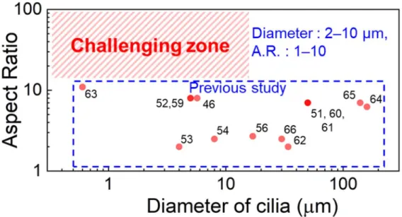
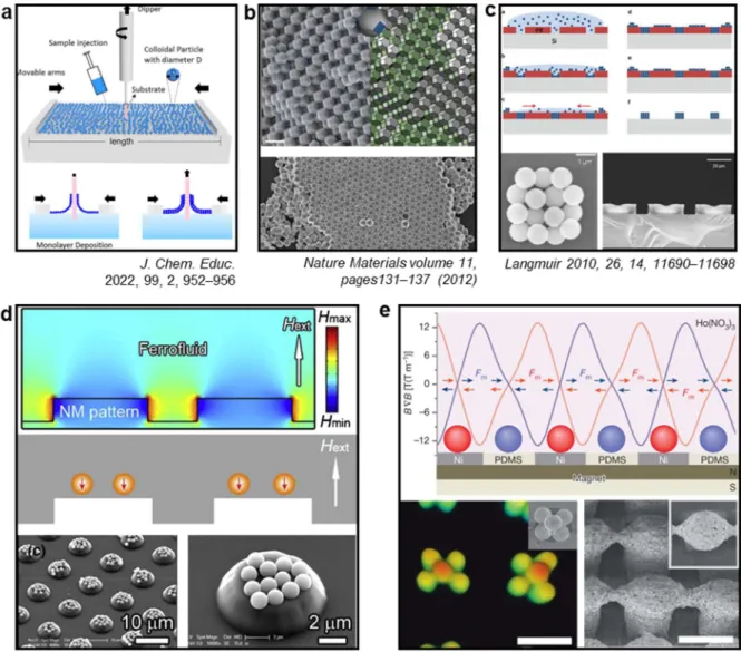
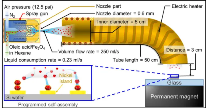
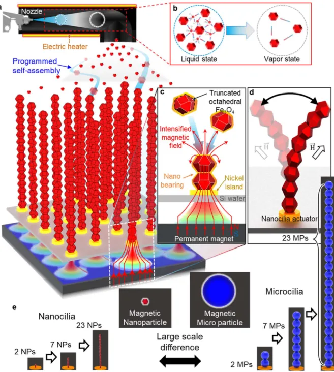
The self-assembly approach emerged as a solution to the limitations of the top-down approach. We demonstrate that the oleic acid used to coat the particles acts as a lubricating bearing and enables the activation of cilia on a rolling/sliding basis. Schematic illustrations showing (a) the programmed self-assembly process of magnetic particles in patterned magnetic fields, (b) the conversion of liquid-state NPs released from a spray nozzle to vapor-state NPs through a heating tube, and (c) individual magnetite NPs, which are attracted to the Ni island by an enhanced magnetic field, and (d) field-responsive activation of assembled nanocilia. e) Schematic illustrations showing the difference in size between nanocilia and microcilia.
Comparison of truncated octahedral magnetite NPs with and without oleic acid. a–i) TEM images showing synthesized magnetite NPs with oleic acid, (a–i,ii) a magnified image of the oleic acid layer coated over the surface with a thickness of 3 nm. SEM images of the assembled (a i,ii) Fe3O4 NPs and (b i,ii) Fe MPs in liquid state. A Field-responsive dynamic movements of nanocilia. a–i) 3D modeling and (a–ii) timelapse optical microscopy images showing the dynamic movement of the 6 NPs cilium in response to changes in the direction of the external magnetic field.
Activating movements of synthetic magnetic eyelashes. a) 3D modeling image showing different working intervals of NP and MP cilia.
Introduction
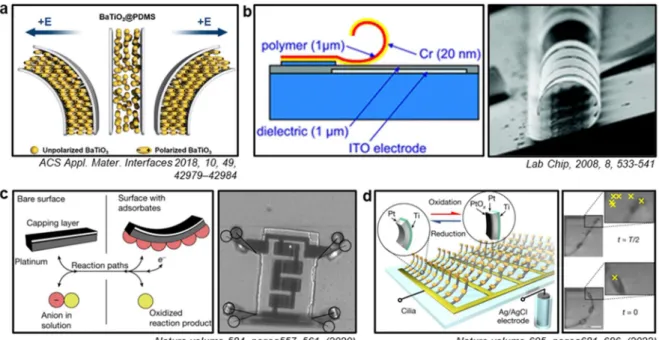
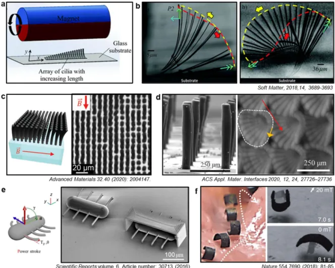
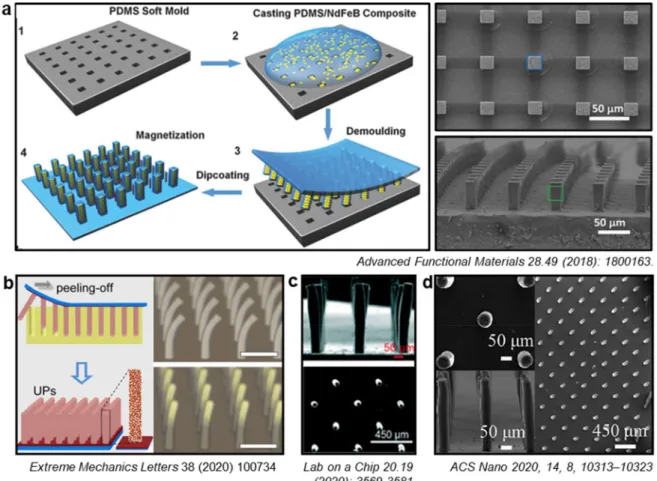
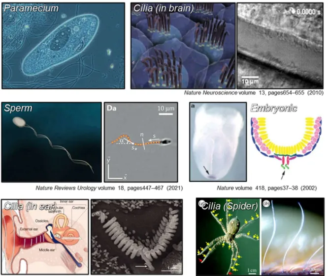
Cilia (in the brain) image reproduced with permission from ref9, copyright 2010 Springer Nature, Sperm image reproduced with permission from ref12, copyright 2021 Springer Nature, Embryonic image reproduced with permission from ref11, copyright 2002 Springer Nature, Cilia (in the ear) image reproduced with permission from ref18, copyright 2004 Springer. Reproduced with permission from ref45, copyright 2018 Royal Society of. c, d) Fabricated microscale artificial cilia and action. Reproduced from ref48 with permission under open license CC. f) Soft body robot controlled by magnetic field.
Reproduced with permission from ref56, copyright 2018 John Wiley and Sons. b-d) Magnet-responsive cilia actuator fabricated by soft molding techniques. A schematic showing the procedure used for magnetic field-based self-assembly and. fabricated product.Reproduced with permission from ref84, copyright 2017 John Wiley and Sons. b-d) Fabricated magneto-responsive cells with magnetic field-based self-assembly techniques.
Construction of new self-assembly process
A custom-built heating tube (internal diameter: 5 cm) was placed in front of the spray nozzle. The position of the Ni pattern substrate is the center of the neodymium permanent magnet, 3 mm above the surface. In the corresponding position, the magnetic force is directed evenly above the surface of the magnet, enabling more uniform vertical self-assembly.
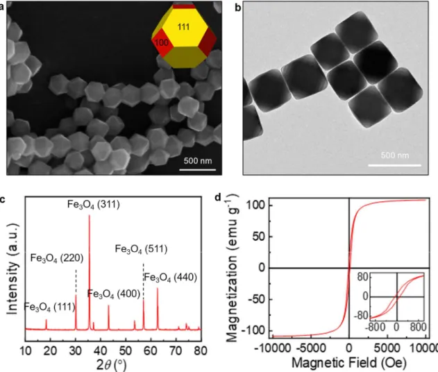
Then, the temperature of the solution was increased to 275 °C at a rate of 20 °C min-1 under vigorous magnetic stirring (900 rpm). The exact shape and size of the synthesized nanoparticles were confirmed via SEM and TEM images (Figure 2.4a,b). Indeed, the TEM image of the magnetite without the OA coating (Figure 2.5c) shows that the amorphous structural material was not observed on the outside of the particles.
-i) TEM images showing synthesized magnetite NPs without oleic acid and (c-ii) enlarged. view of the surface of a NP. In addition, the properties of the magnetic particles were analyzed and a ferromagnetic Ni island was prepared in preparation for the self-assembly process. For the functionality of the NPs and MPs, 0.2 g of magnetic particles and 4 mL of oleic acid were added to the hexane solution (30 mL) and further sonicated for 1 h.
TEM images of the NPs were acquired on a high-resolution TEM system (JEM-2100, JEOL, Japan) operated at 100 keV. The size distribution of the NPs was measured using ImageJ software based on the TEM images. The magnetization of the NPs was measured at room temperature using a superconducting quantum interference device (SQUID) MPMS3 magnetometer (Quantum, USA).
Analysis of self-assembly elements
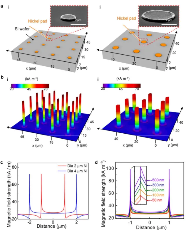
The simulation results show that the magnetic field strength is the highest at the top of the self-assembled particle, which means that there is a high probability that the induced particle will be loaded on top of the assembled particle later. 𝐹 = 3𝑚 (1 − 3𝑐𝑜𝑠 𝜃)/(𝑠 + 2𝑎) (1) where θ is the angle between the direction of the magnetic field and the line connecting the center of the NP, s is the distance (surface-to-surface distance between magnetic particles), a is radius of the particle. This equation shows that the dipole-dipole interaction is attractive along the direction of the magnetic field.
In addition, the magnetic field strength and the magnetic field (white line) were confirmed by simulation in relation to the particle size (Figure 3.2b). In order to lower the energy level as described above, the induced particles are likely to come on top of the existing ordered particles. Simulation of self-assembly of NP cilia and MP cilia. a) Simulated magnetic field strengths for (a-i) one, (a-ii) five and (a-iii) ten NPs assembled on the Ni island.
In addition, the SEM image of the fluid consumption rate 115, 1000 mL s-1 shows the phenomenon that the particles are not well induced and the substrate is contaminated by residues (Figure 3.3b). In summary, we demonstrate that the mechanisms, control of the magnetic field strength with the Ni island and self-assembly in the vapor state, play a major role in the new self-assembly procedure. The FEM simulation shows that the magnetic field strength increases about 5 times near the Ni island when the external magnetic field is applied.
In addition, the magnetic field strength of the self-assembled cilia indicates that the topmost part of the cilia had a high magnetic force, implying that additional induced magnetic particles were likely stacked vertically above the cilia. In addition, the magnetic field strength of the self-assembled cilia was verified, and it was confirmed that the topmost part of the cilia has a high magnetic force, so the additional induced magnetic particles are probably stacked vertically above the cilia. The actual geometry of the system was reflected in the numerical analysis with more than free tetrahedral elements for 3D simulation and more than 350,000 free triangular elements for 2D simulation.
Analysis of self-assembled cilia actuator
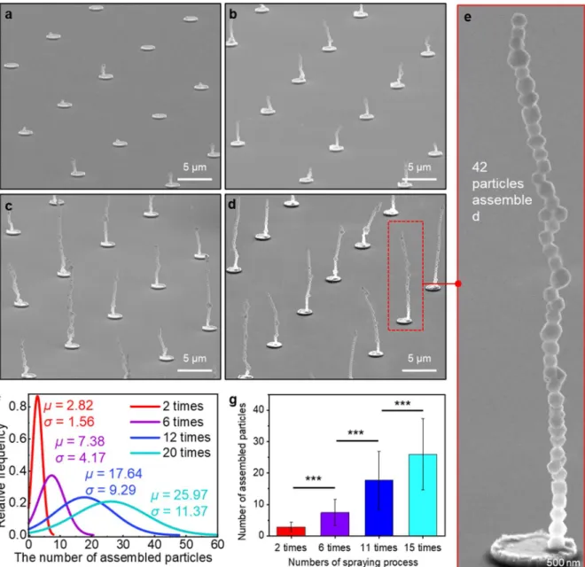
SEM images of an array of self-assembled NP cilia after (a) two, (b) six, (c) twelve, and (d) twenty times sputtering processes. e) Magnified SEM image showing a single magnetic cilium assembled from 42 magnetite NPs in the array of cilia shown in (d). f) Relative frequency of the number of assembled NPs after different numbers of spraying processes. g) Number of NPs assembled. Similar to NPs, MPs can be selectively induced on the Ni island, and the length of assembled MP cilia increases with increasing sputtering cycles. We analyzed which aspects of the NPs mainly came into contact with each other in the self-assembled cilia by examining high-resolution scanning electron microscope (SEM) images of the assembled cilia (Figure 4.7 a,b).
The total interaction potential between two ferrimagnetic NPs with tethered oleic acid can be expressed as the sum of the van der Waals attractive potential (Uvdw), the magnetic dipole–dipole potential (Udd), and the elastic repulsive potential (Uel). We investigated the structural change of the NP cilia in response to an external magnetic field. Very interestingly, we observed that the driving motion of the cilium was achieved by rolling and sliding between two specific adjacent particles of the cilium.
-i) 3D modeling and (c-ii) time-lapse optical microscopy images showing the dynamic movement of the 43 NP cilium in response to changes in the direction of the external magnetic field. d–i) 3D modeling and (d–ii) time-lapse confocal microscopy images showing the responsive movement of assembled MP cilia (MP numbers: 23) inside. Activation of the cilium usually occurred at the interface between the 4th and 5th NPs from the end of the cilium (Figure 4.11a). Based on our FEM simulations, as the direction of the external magnetic field became horizontal (vertical to the cilium), the difference in magnetic field strength between the left and right sides of the cilium became more significant (Figure 4.11c).
Accordingly, activation may occur at the interface between the 4th and 5th NPs from the base of the cilium, as observed in the experiments. To verify the role of oleic acid in the activation of NP cilia, we compared the activation movements of NP cilia with and without oleic acid (Figure 4.12a-f). 𝑇 = 𝑉𝑴 × 𝑩 (6) Here, V is the magnetic cilia volume, M is the magnetization of the magnetic cilia, and B is the flux density of the external magnetic field.
The horizontal translation of the magnet attached to the linear actuator induced field-responsive actuation movement of the magnetic nanocilia. The driving motion of the nanocilia was recorded as high-resolution videos using a confocal microscope (LEXT OLS 3100 Laser, Olympus, Japan).
Conclusion and perspectives
Furthermore, this chapter shows that our self-assembly process has overcome the previous limitations of manufacturing nanoscale or high aspect ratio (>20) microcilia actuators. Furthermore, the torque exerted by the cilia could be adjusted up to several thousand times, depending on the number and size of the composite particles. This study is meaningful because for the first time a programmable nanocilia array was fabricated using the self-assembly approach.
More precisely, under the conditions of the developed system, the height deviation of the self-assembled cilia is large. Further research is needed to reduce this, and one way to solve this problem is to use an ultrasonic nebulizer approach. Furthermore, regarding the rolling/sliding phenomena, it is unclear whether the triggering phenomenon of the cilia is precisely rolling or sliding, and further research is needed to clarify this.
Additionally, further research is needed to investigate how rolling/sliding phenomena vary depending on the shape element of the particle and the coefficient of friction of the material coated on the particle. Cilia are observed on the surfaces of various living organisms; therefore, nano/micro-actuators play a major role in various fields such as labs on a chip, microfluidics,. Therefore, we believe that the self-assembling approach and cilia actuator that we have developed can serve as a basis for next-generation research in the aforementioned areas and a new self-assembling system that can build desired shapes.
Chattopadhyay, P.; Wang, L.; Eychmüller, A.; Simmchen, J., A University Project on the Assembly of Langmuir-Blodgett Films of Colloidal Particles. Singh, G.; Chan, H.; Baskin, A.; Gelman, E.; Repnin, N.; Kral, P.; Klajn, R., Self-assembly of magnetite nanocubes into helical superstructures. P.; Boyd, R.; Expong, J.; Wagberg, T.; Edman, L.; Brenning, N.; Helmersson, U., Catalytic nanotruss structures realized by magnetic self-assembly in pulsed plasma.