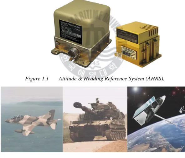
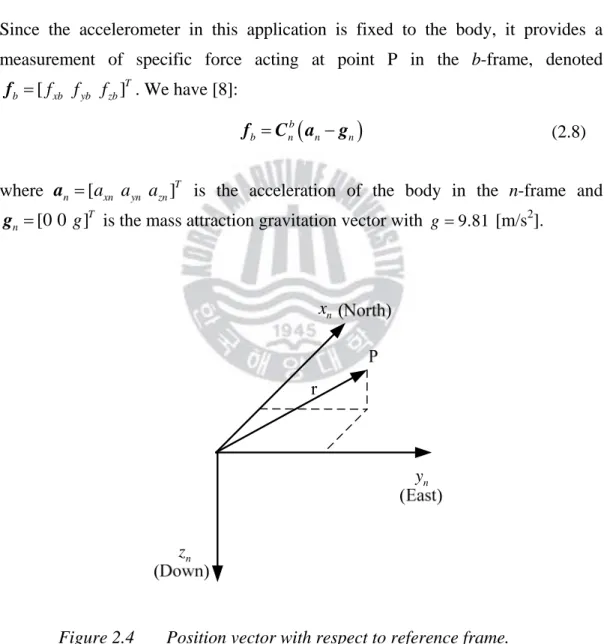
The thesis presents a methodology for the design of a low-cost position and direction estimation system consisting of three single-axis velocity gyroscopes, a three-axis accelerometer and a three-axis magnetometer. The accelerometer is a three-axis digital output linear accelerometer developed by ST that includes a sensor element and an interface IC that can receive information from the sensor element and transmit the measured acceleration signals to the outside world via an I2C/SPI interface. Using this method, we obtained information about the position (tilt and inclination angle) and direction, which are reliable over a long period of time.
I am especially grateful to people for their help, support and encouragement during my study in Korea for the past two years. First of all, I would especially like to thank my supervisor, Professor Ha Yun Su, who gave me good advice about my research work at Korea Maritime University. I would also like to thank Vietnamese friends at Korea Maritime University including: Nguyen Duy Anh, Tran Thanh Ngon, Do Huu Hien, Le Quynh Lam, Vu Manh Dat, Nguyen Hoang Phuong Khanh, Nguyen Tien Thanh, Nguyen Kim Bao.
Finally, I would like to express my deep gratitude to my parents for their love, patience and support.
Introduction
There are several types of sensors from which we can obtain position (tilt and pitch) and heading information. However, this type of sensor has a slow response and therefore cannot be used alone in a position estimation system. Vaganay, Aldon, Fournier [3] proposed a mobile robot position estimation system using an extended Kalman filter to fuse data from accelerometers and gyroscopes.
The estimator has been successfully implemented on a walking robot; however, only attitude angles were estimated. The first is based on the estimator developed by Rehbinder and Hu and dedicates to attitude estimation. The second uses the result of the first to transform the Earth's magnetic field vector measured by magnetometers in body frame to inertial frame.
The heading angle is then calculated from the transformed Earth magnetic field vector and combined with the gyroscope data to reduce noise in the heading estimate.
Theoretical Background
- Attitude and heading representation
- Attitude and heading determination using rate gyros
- Attitude determination using accelerometers
- Heading determination using magnetometer
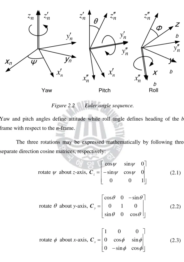
According to Euler's theorem, we can specify the orientation of the body frame relative to the reference frame by three angles (ψ θ φ, , ), known as Euler angles, and obtained by three successive rotations about different axes, known as Euler angle series . Yaw and pitch angles define attitude while roll angle defines the heading of the b-frame with respect to the n-frame. Rotation rates of the body frame relative to the reference frame can be expressed in terms of the derivatives of the Euler angles ( , ,ψ θ φ& & &) called "Euler rates".
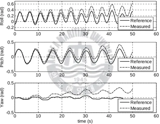
If initial Euler angles and rate gyro data are known, we can calculate Euler angles by solving the above equation using numerical integration. From the above angular velocities, solving Equation (2.6) numerically using the fourth-order Runge-Kutta method, we obtain Euler angles. Because the Euler angles are calculated from true angular velocities, we consider them as reference Euler angles.
From the velocity field measurements, we solve equation (2.6) again, we get the Euler angles considered as measured values. To determine the direction angle ψ from the Earth's magnetic field vector, m components of the vector in the frame h mxh and myh must be known (Figure 2.6). However, in this application, the magnetic field sensor is fixed in the b-frame, it provides a measurement of the Earth's magnetic field vector in the b-frame, denoted
However, the above method of determining the direction angle is valid only in a homogeneous and undisturbed Earth's magnetic field. From the above angular velocities, numerically solve equation (2.6) using the fourth-order Runge-Kutta method, and the Euler angles are obtained. Since the Euler angles are calculated from the actual angular velocities, we treat them as reference.
From these angles, we obtain the rotation matrix which transforms the Earth's magnetic field vector in the n-frame mn to a vector in the b-frame mb. To simulate the inhomogeneous and turbulent magnetic field of the Earth, a noise vector is added to the mn vector after every 5 seconds. The magnetometer measurement can be simulated by adding zero-mean Gaussian white noises with σ =0.1% of the vector magnitude of the Earth's magnetic field to the mb components.
In Figure 2.7, we can see that the error of the direction angle measured using the magnetometer measurement is small when the Earth's magnetic field is homogeneous and vice versa.
Design Attitude and Heading Estimation System
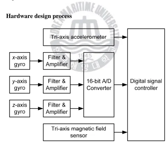
Hardware design process
- Rate gyro sensor
- Tri-axis accelerometer
- Tri-axis magnetic sensor
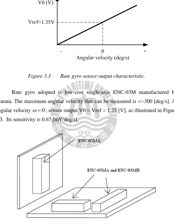
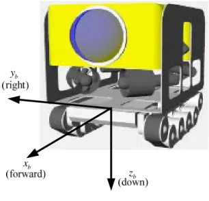
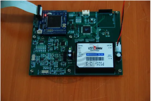
In our approach, three single-axis velocity gyros ENC-03M, a three-axis accelerometer LIS3LV02DQ and a three-axis magnetic field sensor module MicroMag3 are used. They have the same specifications but use different frequencies to avoid mutual interference when fitted to the same system. Thus, two ENC-03MA type rate gyros and one ENC-03MB type rate gyro are used, where the first ENC-03MA type rate gyro and ENC-03MB type rate gyro are installed on the same circuit board, while the second ENC-03MA type rate gyro is installed on a separate printed circuit board, as shown in figure 3.4.
Note that b-frames are right-handed axis sets in which positive rotations about each axis are taken in a clockwise direction, looking along the axis from the origin. Therefore, tempo gyros must be mounted on PCB so that their positive rotations correspond to positive rotations of three axes of b-frame (Figure 3.5). To reduce the effect of temperature shift (due to change of ambient temperature), a high-pass filter should be connected to sensor output to eliminate DC component.
To suppress the output noise component around 22-25 k [Hz] (the resonant frequency of the sensor element), a low-pass filter with a higher cut-off frequency than the required response frequency should be connected to the sensor output (Figure 3.6). It includes a sensing element and an interface IC that can receive information from the sensing element and transmit the measured acceleration signals to the outside world via an I2C/SPI serial interface. In our work, the Y and Z axes of the accelerometer, when mounted on the PCB, have the opposite direction with the yb axis and the zb axis of the b frame.
PNI's three-axis magnetic field detection module, MicroMag3, is used to measure the earth's magnetic field (Figure 3.9). The microprocessor-compatible SPI interface provides easy access to the MicroMag3's measurement parameters and the resulting field measurement data. The MicroMag3 magnetic sensor works as an oscillator circuit consisting of the internal sensors, bias resistors, digital gates and a comparator.
The user sends a command byte to the MicroMag3 through the SPI port specifying the sensor axis to be measured and the sensor will return the result in a 16-bit 2's complement format.
Data fusion algorithm
- Attitude estimator
- Heading estimator
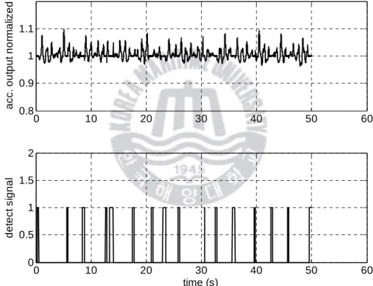
Note that x =1, because x is a column of a rotation matrix and must therefore have unit length [7]. When the system accelerates, the measurement noise vk is large and we can set the covariance matrix Rk of the measurement noise to infinity. It means that when the system accelerates, the attitude estimate is based on speed gyros data only.
This means that in a state without acceleration, the specific force fbi moves along a sphere with a radius of 1g. This condition must hold for a certain amount of time before the system is considered in the no-acceleration state [7]. When the Earth's magnetic field is inhomogeneous and disturbed, the magnetometer data is invalid and the variance of the measurement noise Rk can be set to infinity.
It means that when the Earth's magnetic field is non-homogeneous and disturbed, the direction estimation is based only on the velocity lap data. The problem is how to know whether the Earth's magnetic field is homogeneous and undisturbed or not. It is based on the deviation of the magnetic field norm and dip angle which are calculated from the magnetometer data.
If the magnetic vector lies on the sphere with the normalized radius of 1 and the inclination of the magnetic field is correct, the magnetometer data is valid and the Earth's magnetic field is homogeneous and undisturbed [11].
Simulation Studies
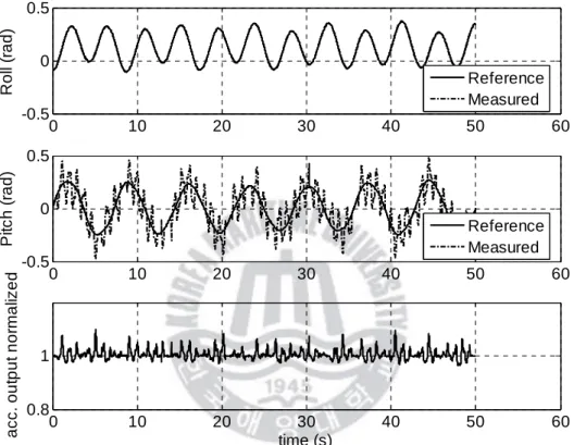
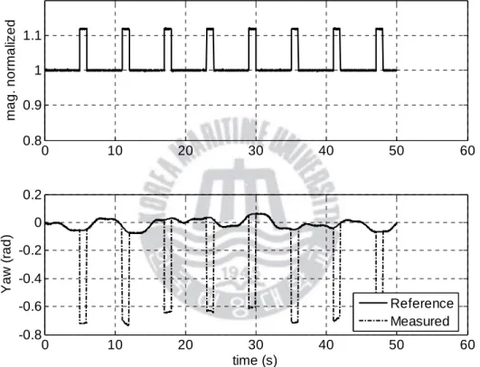
The detection signal is used to switch the attitude estimator between non-acceleration mode and acceleration mode. To simulate the inhomogeneous and perturbed magnetic field of the Earth, a noise vector is added to the vector of the magnetic field of the Earth after every 5 seconds. It causes the normalized magnitude of the change in the Earth's magnetic field vector, as depicted in Figure 4.2.
Error in angle of incidence and Homogeneous & undisturbed earth magnetic field detection signal (Section 3.2.2.3) are also depicted. The detection signal is used to switch the course estimator between two states: homogeneous and undisturbed Earth magnetic field state and inhomogeneous and perturbed Earth magnetic field state. When the detection signal is zero, the heading estimator is in the inhomogeneous and perturbed Earth magnetic field state.
In the figure, solid lines indicate true Euler angles, while dashed lines indicate estimated Euler angles. We can see that there is no drift of estimated Euler angles and noise is reduced. Elements of diagonal of estimated error covariance matrix of the attitude estimator are depicted in Figure 4.5.
There is a slight tendency of increasing errors when the attitude estimator is in acceleration mode. However, these errors are compensated when the attitude estimator is in non-acceleration mode. There is a small tendency of the error to increase when the direction estimator is in the inhomogeneous and perturbed Earth magnetic field mode.
However, this error is compensated when the course estimator is in a homogeneous and undisturbed Earth magnetic field mode.
Conclusions
Durrant-Whyte, “Inertial navigation systems for mobile robots,” IEEE Transactions on Robotics and Automation, vol. Durrant-Whyte, “Evaluation of a Solid State Gyroscope for Robotic Applications”, IEEE Transactions on Instrumentation and Measurement, vol. Borenstein, “FLEXnav: Fuzzy Logic Rule-Based Expert Position Estimation for Mobile Robots in Rugged Terrain,” in Proc.
Musoff, FUNDAMENTALS OF KALMAN FILTERING: A PRACTICAL APPROACH, 2de uitgawe, American Institute of Aeronautics and Astronautics, 2005.