저작자표시-비영리-변경금지 2.0 대한민국 이용자는 아래의 조건을 따르는 경우에 한하여 자유롭게
l 이 저작물을 복제, 배포, 전송, 전시, 공연 및 방송할 수 있습니다. 다음과 같은 조건을 따라야 합니다:
l 귀하는, 이 저작물의 재이용이나 배포의 경우, 이 저작물에 적용된 이용허락조건 을 명확하게 나타내어야 합니다.
l 저작권자로부터 별도의 허가를 받으면 이러한 조건들은 적용되지 않습니다.
저작권법에 따른 이용자의 권리는 위의 내용에 의하여 영향을 받지 않습니다. 이것은 이용허락규약(Legal Code)을 이해하기 쉽게 요약한 것입니다.
Disclaimer
저작자표시. 귀하는 원저작자를 표시하여야 합니다.
비영리. 귀하는 이 저작물을 영리 목적으로 이용할 수 없습니다.
변경금지. 귀하는 이 저작물을 개작, 변형 또는 가공할 수 없습니다.
I
Doctoral Thesis
A Study on Pre-Transition Corrosion Behavior of Zirconium Alloy in Simulated Primary Water
Conditions of Nuclear Power Plant
Taeho Kim
Department of Nuclear Engineering
Graduate School of UNIST
2018
II
A Study on Pre-Transition Corrosion Behavior of Zirconium Alloy in Simulated Primary Water
Conditions of Nuclear Power Plant
Taeho Kim
Department of Nuclear Engineering
Graduate School of UNIST
III
A Study on Pre-Transition Corrosion Behavior of Zirconium Alloy in Simulated Primary Water
Conditions of Nuclear Power Plant
A thesis
submitted to the Graduate School of UNIST in partial fulfillment of the
requirements for the degree of Doctor of Philosophy
Taeho Kim
07. 07. 2018 Approved by
Advisor
Prof. Ji Hyun Kim
IV
A Study on Pre-Transition Corrosion Behavior of Zirconium Alloy in Simulated Primary Water
Conditions of Nuclear Power Plant
Taeho Kim
This certifies that the thesis of Taeho Kim is approved.
07. 07. 2018
V
ABSTRACT
As fuel cladding materials of nuclear power plant, especially pressurized water reactors, Zr alloys have been used, because they have good mechanical properties, and low cross section for thermal neutron capture. Previous studies investigating about the corrosion behavior of zirconium alloy entail ex-situ experiments, however ex-situ methods could influence on the structure and phase stability of oxide film on zirconium alloy. Also, the current management band of DH content is near 2.5 mg/kg, and some discussions arise on the possibility to have it either lower or higher than
currently, for mitigating the corrosion of structural materials of nuclear power plant. However, there is not enough data about the dissolved hydrogen (DH) effect on the oxidation and corrosion
characteristic of Zr alloy at primary coolant water condition.
Therefore, in this thesis, in-situ investigation has been conducted for analyzing the corrosion characteristic of Zr alloy in simulated primary coolant water condition for pressurized water reactors.
To observe the influence of the water chemistry on the corrosion characteristic of Zr alloy for 100 d, Raman spectroscopy is adopted. In-situ Raman spectroscopy and electrochemical impedance
spectroscopy methods have been applied to characterize the phase transformation of zirconium oxide in simulated primary water conditions of pressurized water reactors, and the detail is like follows: 20 MPa pressure, 360 oC temperature by heaters and high-pressure pump, a dissolved oxygen (DO) concentration is lower than 5 ppb, and concentrations of lithium hydroxide (LiOH) and boric acid (H3BO3) are 2 and 1200 ppm, respectively.
The DH concentrations were set as 2.49 and 4.15 mg/kg at standard pressure and temperature for simulating the normal and high DH level. In-situ Raman spectra were collected for zirconium oxide and it represents the phase of zirconium oxide could be different due to the DH concentration. The DH concentration influences on the phase stability of zirconium oxide, and transmission electron microscopy results reveal that at the high DH level, the oxide growth rate is faster than the normal DH concentration due to the strengthened the tetragonal phase to monoclinic phase transformation of zirconium oxide Furthermore, zirconium oxide resistivity is measured, and the resistivity value is relatively low when the oxide is formed at high DH concentration.
To investigate the oxygen chemistry of the O/M interface of zirconium alloy after high temperature water corrosion with different DH levels, the scanning transmission X-ray microscopy and X-ray adsorption spectroscopy techniques were adopted. The oxygen chemistry of zirconium oxide at O/M interface was compared to that of the bulk oxide layer, and O K-edge X-ray adsorption spectra represent the sub-oxide structures are shown in the O/M interface.
VI
Finally, for the fundamental study for the hydration process of zirconium oxide at high
temperature water, high resolution X-ray reflectivity measurement experiment is adopted. The single crystal of YSZ (111) was prepared to characterize the atomistic structure of interface between yttria- stabilized zirconium oxide (YSZ) and water layer using X-ray reflectivity. With high resolution X-ray reflectivity, the hydration structures of YSZ (111) and water interface were measured as sub-
Ångström resolution, at room temperature, and high temperature and pressure condition (340 ℃, 20 MPa). At high temperature water condition, the hydrophobic structure becomes strong, due to the increase of diffusion rate as well as decrease of oxygen vacancy at the YSZ (111) surface layer.
Several pressurized water reactors have been started to manage the water chemistry for mitigating the corrosion of structure material, especially Ni-based alloy and austenite stainless steel.
However, the management of zirconium fuel cladding corrosion is also key issue to guarantee the safety of nuclear power plants. Therefore, the optimized DH concentration should be set after considering the corrosion issues not only structural materials but also zirconium fuel cladding materials. Hence, this Ph.D research investigated the fundamental mechanism of zirconium alloy corrosion from a microstructure point of view, the relationship between DH concentration and corrosion characteristic of zirconium alloy, and finally propose the optimal DH concentration for primary coolant water chemistry.
VII
VIII Table of Contents
Abstract --- V Table of Contents ... VIII List of Figures ... X List of Tables ... XIV
1. Introduction ... 1
1.1. Background ... 1
1.2. Goal and approach ... 2
2. Basic theory and literature study ... 6
2.1 Characteristic of zirconium alloys and zirconium oxide ... 6
2.1.1 Characteristic of zirconium alloys for nuclear industry ... 6
2.1.2 Corrosion kinetics of zirconium oxide ... 7
2.2 Primary water chemistry of pressurized water reactors ... 13
2.3 Raman spectroscopy and electrochemical impedance spectroscopy ... 15
2.4 Scanning transmission X-ray microscopy ... 21
2.5 High resolution X-ray reflectivity ... 25
3. Methods... 31
3.1 In-situ oxide investigation of zirconium alloy using Raman spectroscopy and EIS ... 31
3.1.1 Introduction ... 31
3.1.2 Materials ... 31
3.1.3 Experimental ... 31
3.2 Investigation of electronic structure of zirconium oxide with scanning transmission X-ray microscopy ... 41
3.2.1 Introduction ... 41
3.2.2 Materials ... 41
3.2.3 Experimental ... 41
3.3 In-situ X-ray reflectivity study of interfacial structure between high temperature water and zirconium oxide ... 45
IX
3.3.1 Introduction ... 45
3.3.2 Materials and sample preparation for thin film cell measurement ... 45
3.3.3 Experimental procedure ... 48
4. Results ... 51
4.1 In-situ Raman spectroscopy and EIS results ... 51
4.1.1 In-situ Raman spectroscopy results at normal DH condition ... 51
4.1.2 In-situ Raman spectroscopy results at high DH condition ... 54
4.1.3 In-situ EIS measurement results at two different DH conditions ... 57
4.1.4 Ex-situ characteristic of zirconium oxide after high temperature water corrosion .. 62
4.2 Scanning transmission X-ray microscopy results ... 70
4.2.1 Scanning transmission X-ray microscopy results at normal DH condition ... 70
4.2.2 Scanning transmission X-ray microscopy results at high DH condition ... 76
4.3 X-ray reflectivity results ... 82
4.3.1 X-ray reflectivity results at ambient condition (room temperature, atmospheric pressure) ... 82
4.3.2 X-ray reflectivity results at high temperature water condition ... 90
5. Discussion ... 94
5.1 Characteristic of O/M interface and phase transformation of zirconium oxide ... 94
5.2 Atomistic structure of interfacial layer between zirconium oxide and high temperature water ... 106
5.3 Role of DH on corrosion characteristic of zirconium alloy in high temperature water .... 108
6. Conclusion ... 112
Reference ... 114
Acknowledgement ... 122
X List of Figures
Figure 1-1 Schematic illustration of pressurized water reactors and nuclear fuel assembly [1] --- 3
Figure 1-2 A diagram of goal of this thesis --- 4
Figure 1-3 A diagram of approach of this thesis --- 5
Figure 2-1 Zr-O phase diagram [23] --- 10
Figure 2-2 Schematic representation of corrosion of zirconium alloys [31] --- 11
Figure 2-3 Schematic of energy diagram of Raman spectroscopy --- 17
Figure 2-4 In-situ Raman spectra of zirconium alloy heated to 407 ℃ in aqueous solution [2] --- 18
Figure 2-5 In-situ Raman spectra of zirconium oxide with different temperature [2] --- 19
Figure 2-6 Electrical circuit with solution resistance, charge transfer resistance and double layer capacitor --- 20
Figure 2-7 Schematic diagram of X-ray adsorption spectroscopy edges --- 22
Figure 2-8 Schematic image of STXM analysis instrument in Pohang accelerator laboratory 10A beamline --- 23
Figure 2-9 Example of oxygen K-edge X-ray adsorption spectra [45] --- 24
Figure 2-10 The Bragg scattering geometry (A) X-ray path length for two parralel layers, (B) described by momentum transfer vector, Q [47] --- 28
Figure 2-11 Scattered X-ray intensity as different number of atomic layer, N [47] --- 29
Figure 2-12 The CTR structure factor with different regular separation and outmost layer occupancy [47] --- 30
Figure 3-1 Schematic of in-situ Raman spectroscopic and corrosion experiment for Zr-Nb-Sn alloy - 34 Figure 3-2 Schematic diagram of oxidation loop and autoclave inside for in situ EIS spectroscopy -- 35
Figure 3-3 Equivalent circuit for EIS analysis --- 36
Figure 3-4 The data of conductivity and temperature during passivation procedure --- 37
Figure 3-5 Image of in-situ Raman spectroscopy instrument [54,55] --- 38
Figure 3-6 Schematic of in-situ Raman spectroscopic system with the autoclave and sample --- 39
Figure 3-7 STXM experiment instruments in Pohang accelerator laboratory (PAL) 10 A beamline --- 43
XI
Figure 3-8 Sample and sample holder for STXM analysis --- 44 Figure 3-9 (a) A top view and (b) side view schematic of YSZ (111) substrates --- 47 Figure 3-10 Schematic image and photo of the thin film cell and the experimental geometry for X-ray
reflectivity measurement --- 49 Figure 3-11 Pictures of the hydrothermal cell --- 50 Figure 4-1 In situ Raman spectroscopy results of oxidized Zr-Nb-Sn alloy after different oxidation time
at 2.49 mg/kg DH [61] --- 52 Figure 4-2 In situ Raman spectroscopy results of oxidized Zr-Nb-Sn after different exposure time at
4.15 mg/kg DH [61] --- 55 Figure 4-3 Nyquist plots and fitted plots of in situ EIS for oxidized Zr-Nb-Sn specimen for (a) 10, (b)
20, (c) 30, and (d) 40 days at 2.49 mg/kg DH condition --- 58 Figure 4-4 Nyquist plots of in situ EIS for oxidized Zr-Nb-Sn specimen for 100 days at 4.15 mg/kg DH
condition --- 59 Figure 4-5 TEM images the oxide film on the Zr–Nb–Sn specimen after (a) 30 d, (b) 50 d, (c) 80 d, and
(d) 100 d at 2.49 mg/kg of DH. The red boxes “A”, “B”, and “C” were used for Fast Fourier Transform analysis.[61] --- 64 Figure 4-6 Fast Fourier Transform analysis images of the oxidized Zr–Nb–Sn alloy after (a) 30 d, and
(b) 100 d at 2.49 g/kg DH [61] --- 65 Figure 4-7 TEM images the oxide film on the Zr–Nb–Sn specimen after (a) 30 d, (b) 50 d, (c) 80 d, and
(d) 100 d at 4.15 mg/kg of DH. The red boxes “A”, “B”, and “C” were used for Fast Fourier Transform analysis. [61] --- 66 Figure 4-8 Fast Fourier Transform analysis images of the oxidized Zr–Nb–Sn alloy after (a) 30 d, and
(b) 100 d at 4.15 mg/kg DH. [61] --- 67 Figure 4-9 STXM images of oxidized zirconium alloy for (a) 30 d, (b) 50 d, (c) 80 d, and (d) 100 d at
2.49 mg/kg DH --- 71 Figure 4-10 O K-edge XAS image of oxidized zirconium alloy for 30 d at 2.49 mg/kg DH --- 72 Figure 4-11 O K-edge XAS image of oxidized zirconium alloy for 50 d at 2.49 mg/kg DH --- 73
XII
Figure 4-12 O K-edge XAS image of oxidized zirconium alloy for 80 d at 2.49 mg/kg DH --- 74
Figure 4-13 O K-edge XAS image of oxidized zirconium alloy for 100 d at 2.49 mg/kg DH --- 75
Figure 4-14 STXM images of oxidized zirconium alloy for (a) 30 d, (b) 50 d, (c) 80 d, and (d) 100 d at 4.15 mg/kg DH --- 77
Figure 4-15 O K-edge XAS image of oxidized zirconium alloy for 30 d at 4.15 mg/kg DH --- 78
Figure 4-16 O K-edge XAS image of oxidized zirconium alloy for 50 d at 4.15 mg/kg DH --- 79
Figure 4-17 O K-edge XAS image of oxidized zirconium alloy for 80 d at 4.15 mg/kg DH --- 80
Figure 4-18 O K-edge XAS image of oxidized zirconium alloy for 100 d at 4.15 mg/kg DH --- 81
Figure 4-19 Captured image of peak integration program for XRR data analysis --- 84
Figure 4-20 Measured X-ray reflectivity data (with error bars) for YSZ (111) and water interface as a function of Q at room temperature --- 85
Figure 4-21 A schematic of fitting model for YSZ (111) and water interface --- 86
Figure 4-22 Measured XRR data (blue line + error bars) and the fitting results (red line) for YSZ (111) and water interface at room temperature as a function of Q --- 87
Figure 4-23 Electron density profiles from the fitting results of the XRR data for YSZ (111) and water interface (blue line) room temperature (red line) 340 ℃ flowing cell condition--- 88
Figure 4-24 Measured XRR data (with error bars) for YSZ (111) and water interface as a function of Q at 340 ℃ water --- 91
Figure 4-25 XRR data (blue line + error bars) and the fitting result (solid line) for YSZ (111) and water interface at 340 ℃ water as a function of Q --- 92
Figure 5-1 The thickness of zirconium oxide with different DH conditions [68,77,78] --- 98
Figure 5-2 Comparison of Raman spectra with different DH conditions [61] --- 99
Figure 5-3 Simulated oxygen K-edges from 3 candidate structures along with observed data of the sub- oxide region [70]. --- 100
Figure 5-4 Spectra of Oxygen K edges for the zirconium oxide (ZrO2), oxygen saturated metal (Zr(O)) and the suboxide (ZrO) phases [71]. --- 101 Figure 5-5 In-Lens SEM images. labelled by (1) means the monoclinic phase dominant region, and
XIII
labeled by (2) means the tetragonal phase dominant region. --- 102
Figure 5-6 Calculated oxide resistivity with various oxidation time and oxidation conditions--- 103
Figure 5-7 The resistivity of oxide film on Zircaloy-4 and Zr-2.5 Nb alloys [76] --- 104
Figure 5-8 Schematic of YSZ (111) and water interface structure --- 107
Figure 5-9 Possible model structures for hydrated Zr4+ polycations [82] --- 109
Figure 5-10 The schematic image of water species concentration and the oxide thickness of zirconium alloy at different DH condition at high temperature water environment --- 110
Figure 5-11 A model for corrosion of zirconium alloy in high temperature water condition ... 122
XIV List of Tables
Table 2-2-1 Chemical composition of zirconium alloys for nuclear industry (concentration in wt. % or
ppm) [18] --- 8
Table 2-2-2 Characteristics of zirconium oxide with various phases [25] --- 12
Table 2-2-3 Guideline value of PWR primary coolant chemistry [36] --- 14
Table 3-1 Chemical composition of the zirconium alloy (main alloying elements in wt.%) --- 40
Table 4-1 Raman wavenumber of oxidized Zr-Nb-Sn at 2.49 mg/kg DH --- 53
Table 4-2 Raman wavenumber of oxidized Zr-Nb-Sn at 4.15 mg/kg DH --- 56
Table 4-3 Parameter values after optimization on the experimental impedance data for zirconium oxide at 2.49 mg/kg DH condition --- 60
Table 4-4 Parameter values after optimization on the experimental impedance data for zirconium oxide at 4.15 mg/kg DH concentration --- 61
Table 4-5 Chemical composition of 3 different points in Fig. 4-5 (a). --- 68
Table 4-6 The average values of zirconium oxide thickness with standard deviations of 30, 50, 80, and 100 d from start-up at different DH concentrations --- 69
Table 4-7 Best-Fitted parameters from the YSZ (111) and water interface fitting model for room temperature --- 89
Table 4-8 Best-fitted parameters derived from the fitting model for YSZ (111) and water interface for 340 ℃ --- 93
Table 5-1 The values of peak position and separation in the O K-edge XAS spectra (Unit: eV) --- 105
XV
1 1. Introduction
1.1. Background
As fuel cladding materials of nuclear power plant, especially pressurized water reactors, Zr alloys have been used, because they have good mechanical properties, and low cross section for thermal neutron capture. However, the importance of understanding of the zirconium alloys corrosion mechanism has been a key issue after the Fukushima accident, as they act as the primary shield from the radioactive materials. Figure 1-1 shows a schematic illustration of pressurized water reactors and the nuclear fuel assembly [1]. Also, the degradation behavior of the zirconium cladding affects the accidents of the nuclear reactors. Moreover, zirconium oxide is formed from the metal/water interface, and phase and structure of zirconium oxide influences on its mechanical and chemical properties [2–
4]. Accordingly, the corrosion behavior and mechanism of zirconium alloy should be understood to assure the safety of the nuclear power plants.
The understanding of the transformation mechanism of zirconium oxide from tetragonal phase to monoclinic phase which is enhanced by the water becomes an unsolved issue [5]. Literature results presented the OH- ions are formed by the water ionization, and they fill the vacancy sites of zirconium oxide by diffusing into lattice of zirconium oxide, lowering the concentration of oxygen vacancy and destabilizing the tetragonal phase zirconium oxide [6–8]. The phase transformation mechanism of zirconium oxide in high temperature water is the following; Water is chemically absorbed on the zirconium oxide surface and, by reacting with oxygen (O2−) ions, forms OH− ions on the oxide surface. Then, the OH− ions penetrate the inner part by grain boundary diffusion and fill the oxygen vacancies within the grains. Finally, the tetragonal phase to monoclinic phase transformation occurs because the number of oxygen vacancy is reduced.
Currently, the dissolved hydrogen (DH) concentration is an issue in water chemistry, especially, in primary water chemistry of pressurized water reactors, as the change in the DH concentration can affect the corrosion mechanism of the nickel base alloy [9–12]. The effect of the DH concentration on the oxide formation has been investigated by previous studies [13,14]; however, there are few literatures investigating the effects of the DH level on zirconium oxide and oxide phase transformation in a primary water condition of pressurized water reactor.
Also, the water-metal interface is regarded as the rate-controlling site governing the rapid oxidation transition in high-burn-up fuels. During the corrosion, a tetragonal oxide layer formed on
2
the Zr alloy because of the stress accumulated in the O/M interface. This layer becomes unstable monoclinic oxide phase as the layer thickness increases, thus decreasing the stress [15–17]. Therefore, it is important to determine the types of oxides (i.e., the phases of the oxides) in the oxide layer formed on the zirconium alloy during the in-situ oxidation process. Because it does not require the removal of sample from the oxidation environment, which can influence on the structure and oxide phase of specimen.
Therefore, in this thesis, Raman spectroscopy and X-ray reflectivity (XRR) measurement methods were adopted for in-situ zirconium oxide analysis, which can be used at high pressure and high temperature water environment. From In-situ Raman spectroscopy, it is possible to characterize the oxide phase and oxide film on a metal surface, providing the oxidation mechanisms. From the X- ray reflectivity measurement results, the interfacial structure at oxide/water interface and the early stage corrosion behavior of zirconium alloy can be revealed. Subsequently, ex-situ investigation methods such as scanning transmission X-ray microscopy (STXM), transmission electron microscopy (TEM) were employed to further characterize the oxygen chemistry and the zirconium oxide structure after high temperature water corrosion.
1.2. Goal and approach
The main goal of this thesis is to understand the effect of DH on the corrosion behavior on zirconium alloy at high temperature water from Raman spectroscopy and X-ray synchrotron experimental observations. In-situ Raman spectroscopy has been applied to investigate the phase transformation of zirconium oxide in simulated primary water environments of pressurized water reactors (PWRs) with different DH concentrations. For supporting the phase distribution of zirconium oxide, TEM analysis was also conducted after high temperature water corrosion. The STXM and X- ray absorption spectroscopy were adopted for characterizing the oxygen chemistry of zirconium oxide at O/M interface. To investigate the atomistic structure of zirconium oxide and high temperature water interface, high resolution X-ray reflectivity technique using synchrotron X-ray source was also adopted. Figure 1-2 and 1-3 show a diagram which illustrates the goal and approaches to investigate the corrosion behavior of zirconium alloy at simulated primary coolant loop environment.
3
Figure 1-1 Schematic illustration of pressurized water reactors and nuclear fuel assembly [1]
4
Figure 1-2 A diagram of goal of this thesis
5
Figure 1-3 A diagram of approach of this thesis
6
2. Basic theory and literature study
2.1 Characteristic of zirconium alloys and zirconium oxide 2.1.1 Characteristic of zirconium alloys for nuclear industry
The PWRs utilize the zirconium alloys as fuel cladding materials, and the fuel rods are approximately 9.5 mm diameter and 4 m height. These fuel rods consist the fuel assemblies, and the bundle of fuel assemblies compose the core of nuclear power plant as illustrated in Fig. 1-1. There are various types of zirconium alloy with the different chemical composition of alloying elements. The Table 2-1 presents the chemical composition of the zirconium alloys which are used in the nuclear power plant [18]. Zircaloy-2 was used for the fuel cladding materials of boiling water reactors (BWRs), however due to the hydrogen absorption characteristic of Ni, it was not a suitable candidate for cladding materials of PWRs. Therefore, Zircaloy-4 had been developed, in which Fe was replaced the Ni. Zr-Nb alloy was developed with high Nb contents, however they showed poor behavior for the claddings of BWRs. Nevertheless, Zr-Nb alloys were used for the pressure tubes due to their low hydrogen pick-up characteristic, and they utilized in the Russian Vodo-Vodyanoi Energetichesky Reactor (VVER). Nowadays, M5 and ZIRLO are developed, with controlling Nb, Fe, and S for enhancing the corrosion resistance in the primary coolant environment in PWRs. Both alloys reveal the low corrosion rate and limited irradiation growth.
The alloying elements in zirconium alloy have a low thermal solubility in α-Zr, therefore they form precipitates in the zirconium matrix like second phase particles (SPP) and Laves phases.
Previous study showed that the solute elements like Cu, Nb and Sn in Zr alloy can increase the corrosion resistance [19]. Especially, a high fraction of Nb can be a reason of the β-niobium precipitates in the Zr alloy. It has been reported that these β-niobium precipitates are adsorbed in zirconium oxide, and the oxidation rate of precipitates is much slower than oxidation rate of Zr matrix [20]. Also, the higher Sn concentration zirconium alloy normally leads the cracks in the oxide because of the delayed oxidation caused by the solute elements [21]. In Zr alloy, the Sn and Nb are dissolved and they could be segregated at the grain boundary of zirconium oxide. These Sn and Nb atoms are not oxidized until the value of oxygen potential are enough for oxidizing the Sn and Nb atoms. This can enhance the corrosion resistance of Zr alloy, and it could be one of the evidences of the difference corrosion resistance with the chemical composition of zirconium alloy. Furthermore, the tetragonal phase zirconium oxide can be stabilized by the precipitates from the oxide/metal (O/M) interface, and they could affect the characteristic of oxide conduction [22].
7 2.1.2 Corrosion kinetics of zirconium oxide
The zirconium oxide has 3 different phases: cubic, tetragonal, and monoclinic. The temperature for the phase transition of tetragonal to monoclinic is 1478 K, and it for tetragonal to cubic phase is 2650 K, as illustrated in Fig. 2-1 and Table 2-2. [23–25]. Therefore, the monoclinic and tetragonal oxide phases are only observed after the corrosion experiment, by transmission electron microscopy (TEM), and ex-situ Raman spectroscopy [17,26]. Near the O/M interface, the dominant phase is tetragonal, and the fraction of monoclinic zirconium oxide increases as the distance from the O/M interface increases [27]. Note that, the compressive stress of bulk zirconium oxide is much lower than compressive stress near the O/M interface. It has been reported that, the formation of monoclinic phase oxide is caused by the tetragonal zirconium oxide phase transformation, and it is highly connected to the corrosion resistance of Zr alloy in simulated primary water environment [7,16].
It also has been reported that oxygen ions diffuse inward direction from the oxide surface to the O/M interface during the oxidation [4]. At the beginning of oxidation, a dense and thin tetragonal zirconium oxide was firstly formed because of the compressive stress near the O/M interface, with small size equiaxed grains. The protective oxide film, acted as a barrier, was formed at the pre-transition period, and the tetragonal oxide becomes columnar shape to reduce the stress in the oxide [28]. The oxide layer thickness increases, as the corrosion time increases, however the compressive stress decreases as far from the O/M interface, as a result of the phase transformation of tetragonal to monoclinic oxide [15,29].
8
Table 2-2-1 Chemical composition of zirconium alloys for nuclear industry (concentration in wt. % or ppm) [18]
Sn Nb Fe Cr Ni O S
Zircaloy-2 1.2 ~ 1.5 0.07 ~ 0.2 0.1 0.005 0.12
Zircaloy-4 1.2 ~ 1.7 0.18 ~ 0.24 0.1 0.1 ~ 0.14
M5 0.8 ~ 1.2 ~ 500 ppm 0.11 ~ 0.16 10 ~ 35 ppm
Zr-2.5Nb 1 2.5 ~ 2.6 ~ 650 ppm 0.12 ~ 0.15
ZIRLO 1.2 1 0.1 0.09 ~ 0.12
9
From previous studies, the kinetics of Zr alloy consists of pre-transition and post-transition stages, and the breakaway phenomena occurs during the transition period [30]. A pre-transition stage can be defined by cubic and parabolic growth kinetics and a post-transition stage can be defined by linear growth kinetics [3]. A cyclic oxide growth behavior is generally observed in the post-transition stage, and it can be illustrated by a break down and repair of zirconium oxide occurred after the transition period. From the Wagner’s law for the oxidation kinetics, the oxidation rate of zirconium alloy can be described by an empirical law w = Ctn, where w is the weight gain (units: mg/dm2), t is the oxidation time, and C and n are the constants. Each different zirconium alloy has its own value of n.
The oxidation rate in the pre-transition period is well matched with the empirical law of the oxidation [3,31]. Therefore, the weight gain of zirconium oxide during the corrosion can influence on the rate of oxidation, and it is correlated with the diffusion process across the zirconium oxide layer by the water species and oxygen ions [32,33]. Furthermore, the formation of the nano-sized cracks and the second phase precipitates near the O/M interface prior to the transition period also can influence on the diffusion rate of oxygen ion and corrosion resistance of zirconium alloys [34,35]. Hence, it is essential to investigate the characteristics of the zirconium oxide and O/M interface before the transition period, especially during the early stage oxidation.
The oxidation kinetics of zirconium alloys can be determined by measuring the weight gain or the oxide thickness of the sample as a function of oxidation time, as illustrated in Fig. 2-2 [31]. Also, the diffusion of hydroxyl and oxygen ions occurs in the O/M interface, it plays an important role in the zirconium corrosion mechanism. As mentioned above, the tetragonal phase is dominant in the O/M interface, and 4 different factors can stabilize the tetragonal phase, and they are oxygen vacancies, solute elements, compressive stress, and grain size. Therefore, it is important to control the above factors for enhancing the corrosion characteristic of zirconium alloy in the simulated primary coolant condition.
The phase diagrams yield that the tetragonal zirconium oxide can be stable phase for temperatures over 1150 ℃. However, the tetragonal zirconium oxide can exist at low temperature in the presence of the high compressive stress.
10
Figure 2-1 Zr-O phase diagram [23]
11
Figure 2-2 Schematic representation of corrosion of zirconium alloys [31]
12
Table 2-2-2 Characteristics of zirconium oxide with various phases [25]
Monoclinic Tetragonal Cubic
Temperature range [℃] ~ 1170 1170 ~ 2370 2370 ~ 2680
Density [g/cm3] 5.83 5.86 5.64
Cell parameter [Å]
a=5.147 b=5.206 c=5.313 α=γ=90°
β=99.23°
123123
a=b=5.082 c=5.185 α= β =γ=90°
a=b=c=5.113 α= β =γ=90°
13
2.2 Primary water chemistry of pressurized water reactors
To transfer the heat from the fission reaction of nuclear fuel, the pressurized water reactors (PWRs) adopt the light water for the primary coolant for primary circuit. The PWRs consist of two main systems, primary and secondary circuit. The heated primary coolant flows to the secondary circuit where the steam is generated for rotating the turbines with generating the electric power. The primary coolant condition is maintained pH 6.9 to 7.4, because the operation below pH = 6.9 could lead to heavier corrosion products depositions on fuel cladding. To satisfy the pH condition of primary coolant, the boron concentration is 1200 ppm from boric acid (H3BO3), and the lithium concentration is 2 ppm from lithium hydroxide (LiOH). Boric acid is generally used for a neutron absorber for controlling the activity of the reactor core, but the acidic condition due to boric acid can enhance the corrosion rate of structure materials. Therefore, lithium is used to adjust pH value of primary coolant of PWR. In Table.
2-3, the detail guideline of PWR primary coolant condition has been described.
Also, minimization of dissolved oxygen concentration is one of the important issues of PWR chemistry control, because dissolved oxygen leads the stress corrosion cracking and general corrosion of structure materials of reactor coolant system. For minimizing the corrosion of primary circuit system, hydrogen is added in the primary coolant to maintain the reducing environment. The PWR water chemistry guidelines from EPRI stated that the range of 25 – 50 cm3/kg of DH is recommended, however some have been experiencing primary water stress corrosion cracking degradation of nickel- based alloy [36]. Previous studies mentioned that the DH can influence on the stress corrosion cracking behavior of nickel-based alloy, especially the high DH can delay the crack initiation time and crack growth rate [10,37–39]. Therefore, to mitigate corrosion in structure materials like stainless steel, and Ni-based alloys used in pressurized water reactors, the primary water chemistry is strictly under controlled. But there is not enough data available about the effect of DH levels on corrosion characteristic of zirconium alloy, oxide, and its phase transformation.
14
Table 2-2-3 Guideline value of PWR primary coolant chemistry [36]
Parameter Guideline value
Dissolved oxygen [ppb] Below 5
DH [cm3/kg, STP] 15 ~ 50
F [ppb] Below 50
Cl [ppb] Below 50
SiO2 [ppb] Below 100
SO4 [ppb] Below 50
15
2.3 Raman spectroscopy and electrochemical impedance spectroscopy
When the light is scattered into the materials, the scattered light has different frequency compared to the incident light, and this phenomenon was first discovered by C.V. Raman. The target molecule adsorbed the energy of the scattered light, and it leads the vibration motion of molecules and the frequency changes of light. To observe the Raman shift, the target molecule should be symmetric structure, and the Stokes Raman scattering is generated by relaxation of molecule from exited state to the first vibration energy state. Anti-Stokes Raman scattering occurs when the molecule is already in the elevated vibration energy state. Figure 2-3 illustrates the energy diagram of Raman scattering.
Previous research adopted Raman spectroscopy for analyzing the oxide characteristic in aqueous solution, especially high temperature condition [40,41]. Most of all, in-situ Raman spectroscopy was adopted to study the corrosion mechanism of metal alloys in high temperature aqueous solution. Also, the effects of water chemistry, including dissolved oxygen levels and boron concentration, were investigated from previous study, and surface enhanced Raman spectroscopy technique was also used for enhancing the signal-to-noise ratio with using noble metal [41,42].
Zirconium alloy was also analyzed with in-situ Raman spectroscopy in air-saturated water at a pressure of 15.5 MPa and temperatures ranging from room temperature to 400 ℃ in optical flow cell. Figures 2- 4 and 2-5 represent the Raman spectroscopy results with comparing monoclinic zirconium oxide power, and different temperature. This reveals that the characteristic of zirconium oxide could be influenced by the water temperature.
However, there is not enough Raman analysis data for zirconium oxide formed at high temperature water condition, especially simulated primary water coolant loop environment of PWRs.
Therefore, in-situ Raman spectroscopy was adopted to analyze zirconium oxide in primary coolant condition. Also, the DH levels were changed for investigating the effect of DH level on transformation of zirconium oxide phase during corrosion.
Electrochemical impedance spectroscopy (EIS) is a well-established analysis method for investigating the electrochemical reactions, with measuring the characteristic of oxides, coated materials, and electrodes. This EIS method can be applied for lots of research areas, including the corrosion research field. The Ohm’s Law is a fundamental law for the electric field, and it states the current through a conductor between two spots is proportional to the voltage of two spots. It can be defined as R=V/I, where R is a resistance of circuit in ohms (Ω), V is the voltage in volts (V), and I is the resulting current flow of the circuit in amperes (A). In alternating current circuit, the impedance (Z) can be defined as a value of circuit tendency to impede the current flow. The Z can be expressed as Z = Vac/Iac where Vac is the potential applied the alternating current circuit and Iac is the current output.
Figure 2-6 illustrates the circuit with the solution resistance Re, and in series with a charge transfer resistance Rct in parallel with a double layer capacitor of oxide Cdl. In this circuit, the impedance
16
can be calculated the summation of ZRE and Z of parallel circuit of double layer capacitance and resistance. The impedance response is consisted of real part of impedance and imaginary part of impedance, Z = Zr + jZj where Zr represents the real part of impedance, and Zj is the imaginary part of impedance. (j = √−1). From the EIS measurement, the thickness of oxide can be calculated with using permittivity of oxide materials, and the capacitance of the oxide from Nyquist plot.
17
Figure 2-3 Schematic of energy diagram of Raman spectroscopy
18
Figure 2-4 In-situ Raman spectra of zirconium alloy heated to 407 ℃ in aqueous solution [2]
19
Figure 2-5 In-situ Raman spectra of zirconium oxide with different temperature [2]
20
Figure 2-6 Electrical circuit with solution resistance, charge transfer resistance and double layer capacitor
21 2.4 Scanning transmission X-ray microscopy
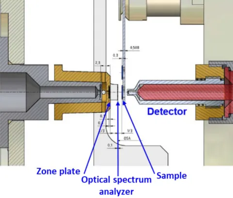
Scanning transmission X-ray microscopy (STXM) is one method of X-ray microscopy, X-ray beam focuses onto a small spot of a sample. X-ray from zone plate passes the optical spectrum analyzer and it scans the sample on the sample holder. The intensity of transmitted X-ray is recorded with the position of the sample. The schematic of STXM is presented in Fig. 2-6. STXM analysis can give high spectral resolution about 20 ~ 30 nm, and the radiation damage on the sample from STXM analysis us two orders of magnitude lower than electron energy loss spectroscopy.
X-ray absorption spectroscopy (XAS) is also synchrotron X-ray based techniques, which can reveal the electronic and geometric structure of a sample. With using a crystalline monochromator, the photon energy can be tuned, and the core electrons could be excited from 100 eV to a few hundred keV.
The excitation of a 1s electron occurs at K-edge, and it of 2s and 2p electrons occurs at L edge. In addition, the excitation of 3s, 3p, and 3d electrons occurs at M edge. One of the XAS analysis is X-ray absorption near edge structure (XANES), and the other is extended X-ray absorption fine structure (EXAFS). XANES uses photoelectron which has the energy range from 10 to 150 eV. EXAFS uses the relative high kinetic energy. Previous studies suggested that XAS are sensitive for analyzing the thin film structure, especially thin oxide on the metal during the corrosion [43,44]. In this thesis, STXM method is adopted for investigating the effects of DH on corrosion characteristic of zirconium alloy and phase distribution of zirconium oxide. The electronic structure of thin film oxide can be revealed by STXM analysis after sample preparation with focused ion beam (FIB) method. The structural properties could be examined by using synchrotron X-ray at soft X-ray Nanoscopy beamline (10 A beamline of Pohang Accelerator Laboratory (PAL), South Korea). Local electronic structure of the oxidized zirconium samples is investigated by using X-ray absorption fine structure spectroscopy at the O K- edge, and the energy range of O K-edge is set as 520 to 560 eV.
22
Figure 2-7 Schematic diagram of X-ray adsorption spectroscopy edges
23
Figure 2-8 Schematic image of STXM analysis instrument in Pohang accelerator laboratory 10A beamline
24
Figure 2-9 Example of oxygen K-edge X-ray adsorption spectra [45]
25 2.5 High resolution X-ray reflectivity
The mineral-water interface is one of the important issues of corrosion of metal, because the first step of corrosion reaction is occurred in water and metal interface. There are plenty of previous studies which treat the X-ray reflectivity measurement, and the basic theory of the X-ray reflectivity (XRR) has been summarized by P. Fenter [46,47]. The basic technology is to reflect direct X-ray beam to atomic flat surface and measure the intensity of reflected X-ray beam in the specular direction. If the interface is not flat layer, the interference of wave occurs, and destructive and constructive interferences can be observed. All waves have the interference characteristic and the reflectivity of X-ray follows the Bragg’s law as shown in equation 2-1.
nλ= 2dsin(θ) (2-1)
In equation 2-1, n is the diffraction order, λ is the wavelength, and d represents the d-spacing of Bragg plane, where θ is the incident angle of X-ray. Also, the interference condition could be described by reciprocal lattice with using momentum transfer vector, Q, which has both a direction and a magnitude. Figure 2-9 illustrates the Bragg’s scattering geometry with angular term and momentum transfer terms. Equation 2-1 can be replaced by using momentum vector, and it is shown in equation 2- 2.
𝐐𝐐=𝐊𝐊𝐟𝐟− 𝑲𝑲𝒊𝒊 =𝑘𝑘(𝒖𝒖𝒇𝒇− 𝒖𝒖𝒊𝒊) (2-2)
Q = |𝑸𝑸| =4π
𝜆𝜆 sin (𝜃𝜃) (2-3)
In Equations 2-2 and 2-3, 𝒖𝒖𝒇𝒇 and 𝒖𝒖𝒊𝒊 are the unit vector of reflected and incident beam, respectively with having a wave vector 𝑲𝑲= 2𝜋𝜋/𝜆𝜆. 𝑸𝑸 has the unit of inverse Ångstroms (Å-1). The reflected beam intensity depends on the distribution of atomic positions along the surface normal direction.
The intensity of scattered X-ray is calculated by summing the amplitudes of scattered beam, ϵj, for each atom j. Then, the reflected beam intensity should be proportional to the structure factor of surface material, F, and the sum of scattered X-ray intensity is proportional of square of F. In equation 2-4, the relationship between intensity and structure factor is illustrated.
𝐼𝐼 ∝ �� 𝜖𝜖𝑗𝑗�2= |𝐹𝐹|2 (2-4)
In real case, the incident X-ray is scattered at every single atomic layer of target material, and it can be defined that the number of atomic layer is N. Then, the structure factor for N-silt layer is defined in equation 2-5, where c is regular separation of atomic layer and f0 is the scattering strength of the layer.
𝐹𝐹=𝑓𝑓𝑜𝑜[(1 + exp(−𝑖𝑖𝑖𝑖𝑖𝑖) + exp(−𝑖𝑖2𝑖𝑖𝑖𝑖) +⋯+ exp[−𝑖𝑖(𝑁𝑁 −1)𝑖𝑖𝑖𝑖)] (2-5)
26
=𝑓𝑓0exp�−𝑖𝑖(𝑁𝑁 −1)𝑖𝑖𝑖𝑖
2 �[sin�𝑁𝑁𝑖𝑖𝑖𝑖2 � sin�𝑖𝑖𝑖𝑖2� ]
Figure 2-10 illustrates the calculated scattered X-ray intensity as different number of atomic layer, N.
Then, the scattering intensity can be presented as equation 2-6.
𝐼𝐼 ∝ |𝐹𝐹|2=𝑓𝑓02[sin2�𝑁𝑁𝑖𝑖𝑖𝑖2 �
sin2�𝑖𝑖𝑖𝑖2� ] (2-6)
The intensity of scattered X-ray is flat for N = 1, which indicating that the interference is not occurred because one single layer does not have something to interfere. As N value increases, the scattered intensity increases to Bragg peak position, and intensity and sharpness of Bragg peaks develop as N becomes large [47].
For Semi-infinite lattice, it does not show high frequency oscillations between the Bragg peaks.
This is because X-ray that scatters from the top interface has nothing with which to interfere. The linear attenuation of X-rays over a distance, 𝑥𝑥, follows the form exp�−𝑥𝑥𝛬𝛬�, where Λ is the linear attenuation length, and η is the typical per-layer attenuation factor.
𝐹𝐹𝑐𝑐𝑐𝑐𝑐𝑐 =𝑓𝑓𝑜𝑜[(1 +𝜂𝜂exp(−𝑖𝑖𝑖𝑖𝑖𝑖) +𝜂𝜂2exp(−𝑖𝑖2𝑖𝑖𝑖𝑖) +⋯
(2-7) +𝜂𝜂N−1exp[−𝑖𝑖(𝑁𝑁 −1)𝑖𝑖𝑖𝑖)]
=𝑓𝑓0 𝜂𝜂𝑁𝑁exp(−𝑖𝑖𝑁𝑁𝑖𝑖𝑖𝑖)−1
𝜂𝜂exp (−𝑖𝑖𝑖𝑖𝑖𝑖)−1 =𝑓𝑓0 1 1− 𝑒𝑒−𝑖𝑖𝑖𝑖𝑐𝑐
The equation 2-7 can be derived with assuming that the value of N becomes very large, and 𝜂𝜂< 1, 𝜂𝜂𝑁𝑁 ≈0. Therefore, equation 2-8 can be derived from equation 2-7.
𝐼𝐼𝑐𝑐𝑐𝑐𝑐𝑐 ∝ |𝐹𝐹|2= |𝑓𝑓0| 4𝑠𝑠𝑖𝑖𝑠𝑠2�𝑖𝑖𝑖𝑖2�
2
(2-8) Figure 2-11 illustrates the crystal truncation rod (CTR) structure factor with different regular separation and outmost layer occupancy. The intensity of scattered X-ray is influenced by the distance of each atomic layer and the electron density of the target layer, which is the occupancy of the atom. It leads that the shape of CTR structure factor is very sensitive to the termination structure of the target material structure. Consequently, the quantity of the CTR structure factor can be divided into two parts, the Fsurf
from the modified surface layer, and Fsub from the semi-infinite substrate of the target crystal structure.
Previous studies introduced the XRR measurement technique for investigating the water interaction with metal surfaces like corrosion, hydration, and electrochemistry reaction [48,49]. The sub-Ångström scale structure of water/oxide interface can be investigated with XRR measurement;
however, it should be conducted with data analysis because the obtained data from XRR measurement is the intensity of scattered light, and the goal of XRR experiment is the electron density of the particular atom. The effective electron density of each atom ρeff(𝑧𝑧) can be written as a Gaussian function in
27 equation 2-9.
ρeff(𝑧𝑧) = 𝑍𝑍
(2𝜋𝜋)12𝑢𝑢𝑒𝑒𝑒𝑒𝑒𝑒exp [−1
2�𝑧𝑧 − 𝑧𝑧0
𝑢𝑢𝑒𝑒𝑒𝑒𝑒𝑒 �
2
] (2-9)
where 𝑧𝑧0 can be determined by the position of material, 𝑢𝑢𝑒𝑒𝑒𝑒𝑒𝑒 is determined by electron distribution, and 𝑍𝑍 is the atomic number of the element. Therefore, the resolution of XRR measurement can be derived like following equation 2-10, where 𝑖𝑖𝑚𝑚𝑚𝑚𝑥𝑥 is the maximum value of scattering data.
Lres = 2𝜋𝜋/𝑖𝑖𝑚𝑚𝑚𝑚𝑥𝑥 (2-10)
From XRR measurement, the single crystal yttria-stabilized zirconium oxide (YSZ) (111) substrates were used for investigating the hydration structure of water/oxide interface. 15.000 keV incident X-ray was used, and the focused beam size was 0.1 mm (vertical) × 0.7 mm (horizontal) with the flux of ∼1.1 × 10¹¹ photons/s.
28
Figure 2-10 The Bragg scattering geometry (A) X-ray path length for two parralel layers, (B) described by momentum transfer vector, Q [47]
29
Figure 2-11 Scattered X-ray intensity as different number of atomic layer, N [47]
30
Figure 2-12 The CTR structure factor with different regular separation and outmost layer occupancy [47]
31 3. Methods
3.1 In-situ oxide investigation of zirconium alloy using Raman spectroscopy and EIS 3.1.1 Introduction
As mentioned in section 2.1, there are three different phases of zirconium oxide, monoclinic, tetragonal, and cubic. TEM analysis can be found the tetragonal and monoclinic zirconium oxide, however previous reported work on zirconium oxide are limited, because ex-situ analysis methods were only adopted [34,50–52]. The corrosion environment can influence on the structure and phase of the zirconium oxide formed on the specimen. Therefore, in this thesis, in-situ Raman spectroscopy was used for in-situ investigations, as the experimental system can be used at the high pressure and temperature water environment. In-situ Raman spectroscopy can be used for investigating the phase and characteristic of oxide film on metal surface. Then, in-situ EIS can measure the capacitance value of oxide layer during the oxidation, and the resistivity value of zirconium oxide can be calculated.
3.1.2 Materials
A plate of Zr-Nb-Sn alloy was used for corrosion experiment at the simulated primary coolant water condition. In Table. 3-1, the chemical composition of Zr-Nb-Sn alloy is illustrated. The plate of Zr–Nb–Sn alloy sample was ground from 400 to 800 grits with SiC papers and polished up to 1 μm with diamond pastes. Lastly, a colloidal alumina paste (0.05 μm) was used to polish the Zr-Nb-Sn alloy for minimizing the deformation of specimen.
3.1.3 Experimental
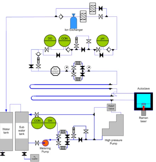
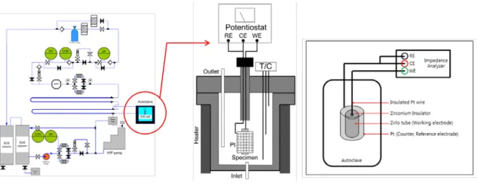
For simulating the high pressure and temperature conditions of PWRs, a system including water chemistry controlling loop and autoclave was constructed. The schematics of the system used for the corrosion experiment, in-situ Raman analysis, and EIS analysis are illustrated in Figs 3-1 and 3-2. Using those instruments, the temperature was set as 360 ℃ and the pressure was set as 20 MPa for simulating the primary water of PWRs, with using the high-pressure pump, pre-heater, and band heaters. Distilled water (18 MΩ·cm) was used for producing primary circuit condition, which contained 1200 ppm boron ion from H3BO3 and 2 ppm lithium ion from LiOH. Also, the dissolved oxygen level can be controlled below 6 ppb, and the pH is controlled from 6.9 to 7.4. In addition, back pressure regulator was instrumented for adjusting the DH level from 2.49 to 4.15 mg/kg.
In Fig 3-3, the equivalent circuit for EIS analysis is represented. The zirconium oxide has two layers, one is a barrier layer and the other one is an outer layer. The barrier layer thickness is tens of
32
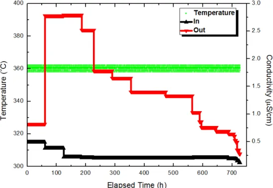
nanometers, however the outer layer have a greater oxide thickness (maximum 100 μm) [53]. The zirconium oxide is divided into two layers and each layer has its own resistivity and capacitance. Using equivalent circuit, the capacitance can be calculated using Z-view simulation and the oxide thickness of each layer is obtained. The Re is a solution resistance, Rin is inner layer resistance, Rout is an outer layer resistance, Cout is an outer layer capacitance, Cin is inner layer capacitance, and Wo is Warburg element of the circuit. After consummating the corrosion experiment system, the shakedown process had been started for preventing the unexpected effect on zirconium oxidation from the oxide from autoclave. The passivation of autoclave was conducted at the same condition of zirconium corrosion experiment, 360 ℃ and 20 MPa with bubbling with nitrogen and oxygen for making fully oxidized autoclave surface. In Fig. 3-4, the conductivity and temperature data during the passivation procedure is represented. At the final step of passivation, the outlet conductivity was below 0.25 μS/cm.
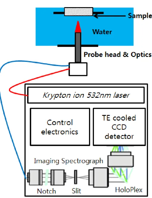
In this study, in situ Raman spectroscopy measurements were performed using a RamanRXNTM, manufactured by Kaiser Optical Systems, Inc., which uses a 532-nm-wavelength krypton ion laser with a maximum power of 100 mW, and the irradiation area in the specimen was 100 μm2. For preventing the beam radiation damage to the zirconium alloy specimen, the power density at the specimen surface was held below 10 mW/cm2. The detail descriptions of the in situ Raman system are presented in the authors’ previous studies [9,50].
In situ Raman spectroscopic measurements with the corrosion tests were performed for Zr- Nb-Sn alloy in a primary water of pressurized water reactors with using an autoclave system, which is specially constructed for the present study. The water chemistry data including exposure temperature, pressure, conductivity, dissolved oxygen, and dissolved hydrogen concentration were measured and strictly controlled.
The Zr-Nb-Sn specimens were exposed until 100 d for two different dissolved hydrogen levels, 2.49 and 4.15 mg/kg. And, the in-situ Raman spectra were measured for 30, 50, 80, 100 d from start- up. The measured Raman spectra were compared for investigating the effects of dissolved hydrogen on the corrosion characteristic of zirconium alloy. For each measurement, in situ Raman spectra was collected for 30 m and repeated 2 times for increasing the signal-to-noise ratio. Prior to analyzing Raman peaks analysis, the baseline correction and Svizy-Golay methods were performed for the smoothening process. After each in situ Raman spectroscopy measurement, the Zr–Nb–Sn alloy specimen was removed from the autoclave for ex situ measurements.
The ex situ investigation was performed to characterize the oxide layer of the specimen using JEOL JEM-2100F TEM in coincidence with energy dispersive X-ray spectroscopy. The focused Ga-ion beam milling method was employed using a Quanta 3D Dual-Beam SEM to prepare the TEM samples.
Prior to focused ion beam milling process, the specimen surface was coated using carbon sputtering to prevent ion beam damage and surface contamination. The acceleration voltage, and the lattice resolution
33
were 200 kV, and 0.102 nm, respectively. In situ Raman spectroscopy and the TEM analysis results were compared for a comprehensive understanding of the effects of dissolved hydrogen on the zirconium oxide characteristics.
34
Figure 3-1 Schematic of in-situ Raman spectroscopic and corrosion experiment for Zr-Nb-Sn alloy
35
Figure 3-2 Schematic diagram of oxidation loop and autoclave inside for in situ EIS spectroscopy
36
Figure 3-3 Equivalent circuit for EIS analysis
37
Figure 3-4 The data of conductivity and temperature during passivation procedure
38
Figure 3-5 Image of in-situ Raman spectroscopy instrument [54,55]
39
Figure 3-6 Schematic of in-situ Raman spectroscopic system with the autoclave and sample
40
Table 3-1 Chemical composition of the zirconium alloy (main alloying elements in wt.%)
Element Nb Sn Fe Hf C N O Zr
Composition 0.96 0.76 0.18 0.002 0.1 0.03 0.62 Balance
41
3.2 Investigation of electronic structure of zirconium oxide with scanning transmission X-ray microscopy
3.2.1 Introduction
Investigation based diffraction studies has shown that due to the compressive stresses, tetragonal phase fraction is the highest near the O/M interface, where the compressive stress is relatively higher than the middle of the zirconium oxide. As oxidation time increases, the proportion of monoclinic zirconium oxide increases while that of tetragonal oxide decreases [17,56]. Detailed characterization of the oxide structure and the tetragonal phase fraction using high-energy synchrotron X-ray diffraction on zirconium alloys and metastable tetragonal phase fraction is previously reviewed: The previous study has shown that X-ray absorption spectra are sensitive to the thin film structure [43]. However, the corrosion of zirconium alloy is quite complex, and the corrosion of zirconium alloy starts by a protective oxide film, with following a parabolic oxidation rate [57]. To identify structure of the zirconium oxide, and the O/M interface, EELS (electron energy loss spectroscopy), and APT (atom probe tomography) have adopted a layer zirconium oxide before the first abrupt transition [4]. In this thesis, a Zr-Nb-Sn alloy is used for investigating with scanning transmission X-ray microscopy (STXM) for 100 d oxidation, which is close to the first transition time of the zirconium alloy oxidation.
3.2.2 Materials
For STXM analysis, the Zr–Nb–Sn specimens were oxidized for 100 d at 2.49 and 4.15 mg/kg DH conditions, and the oxidized samples were obtained after 30, 50, 80, and 100 d from the beginning of the experiment condition. The detail explanation about the corrosion experiment is illustrated in section 3.1.3.
3.2.3 Experimental
For STXM experiment, the focused ion beam method is adopted for sample preparation. For preventing the surface contamination from beam damage and impurities during the process, the surface was coated with sputtered carbon before gallium ion milling. The detail process of FIB process is presented in section 3.1.3.
The structural properties were examined by using the synchrotron X-ray at soft X-ray
42
Nanoscopy beamline (10 A beamline of Pohang Light Source, Republic of Korea). Local electronic structure of the oxidized zirconium samples was investigated by using X-ray absorption fine structure spectroscopy at the O K-edge, and the energy range of O K-edge is set as 520 to 560 eV. The monochromatic X-ray from beamline passes through the exit silt, and the size of it is from 10 to 30 μm.
After exit slit, the X-ray penetrates the zone plate, and the zone plate acts as the focusing lenses if X- ray. Then, the optical spectrum analyzer adjusts the energy range of the incident X-ray. The sample is scanned by the incident X-ray, and the change of intensity of penetrated X-ray is detected at photon counter (detector). The resolution of STXM analysis is about 20 nm, and the X-ray scanning is conducted at the 100 kPa helium condition and the temperature is room temperature. The detail image of STXM experiment faculty is presented in Fig. 3-7, and the sample which is attached on the sample holder is presented in Fig. 3-8.
43
Figure 3-7 STXM experiment instruments in Pohang accelerator laboratory (PAL) 10 A beamline
44
Figure 3-8 Sample and sample holder for STXM analysis
45
3.3 In-situ X-ray reflectivity study of interfacial structure between high temperature water and zirconium oxide
3.3.1 Introduction
In aqueous environment, the metal is oxidized due to the water species and the metal interaction, and also, water interaction with the metal surface is an important process such as corrosion electrochemistry [48]. Especially, the oxygen ions diffuse inward direction from the oxide surface to the O/M interface during the corrosion process, and the water species including oxygen ions and hydroxyl ions are formed in the water/solid interface. Therefore, it is highly required to investigate the interfacial structure of the water and the top layer of the alloy surface. The structural characteristic influences on the ion exchange between water and the metal, and it also effects on the corrosion characteristic of metal.
The reactions occurred at the metal oxide and water interface play an important role to determine the conditions of oxide degradation and corrosion propagation on meatal surface. Synchrotron based in-situ X-ray reflectivity technique has been applied for investigating various solid-water interfaces and addressed the fundamental questions by directly revealing the atomic or molecular scale structure at the interface. Its application to zirconium oxide and water interface is expected to reveal the detailed hydration and chemical processes at the interface, which is expected to contribute to solving the engineering problems in nuclear power plants.
3.3.2 Materials and sample preparation for thin film cell measurement
The YSZ single crystal (8 mol% Y2O3) were purchased from MTI Corporation in the dimensions of 10 × 10 × 1.0 mm3 for (111) surfaces. The lattice constant, a0, is 5.140 ± 0.008 Å. Along the surface normal direction of [111], the new unit cell structure is hexagonal packing and the lattice constants reduce to a = a0/√2, and c = a0/√3, resulting in d111 = 2.968 Å. The unit cell consists of one and one-half O atoms at the z = 0 plane, three Zr atoms at the z = ¼-d111 plane, three O atoms at the z = ¾-d111 plane, and one and one-half O atoms at the z = d111 plane. Along the surface normal direction, the stacking of unit cells results in periodic translations of three O, three Zr, and three O layers. The detail structure of YSZ (111) substrates is illustrated in Fig. 3-9. As shown in Fig. 3-9, All the termination atoms for the YSZ (111) substrates are oxygen, and it has a periodic plane arrangement of O-Zr-O-O-Zr-O.
46
The single crystal was washed in acetone, methanol, and distilled water with sonication for about 10 minutes at each step. This procedure was conducted a few times to remove the impurities on the substrate. The sample was kept in distilled water just after cleaning, until the sample was mounted to the cell for in-situ XRR analysis. The MTI Corporation (the brand name of the YSZ single crystal vendor) specified the miscut angle is less than 0.5°, which is far bigger than a typically acceptable tolerance level, 0.1°, but the polishing quality and the sample dimension precision was impressively high. The quantitative analysis is planned to obtain a deep insight into the hydration and chemistry of the ZrO2/water interface.
47
Figure 3-9 (a) A top view and (b) side view schematic of YSZ (111) substrates
48 3.3.3 Experimental procedure
The X-ray reflectivity measurement was performed at beamline Argonne Photon Source (APS) 33BM-C and at 9C beamline of the Pohang Light Source (PLS) at the Pohang Accelerator Laboratory (PAL) for (111) substrates. At 33BM-C beamline from Advanced photon source (APS), the full beam size at the sample was 0.1 mm (for the low 2θ angles to prevent beam spill-off) and 0.5 mm in vertical, and 0.8 mm in horizontal direction. The monochromatic beam (21 keV, ΔE/E ≈ 10-4) was chosen by a Si (111) double crystal monochromator. The incident photon flux was ~1010-1011 photons/sec. The beamline is equipped with a four-circle [47] diffractometer for surface diffraction experiment and a Pilatus 100K area detector is used as a default detector for the X-ray reflectivity measurement. An area detector, Pilatus 200K, was used for collecting the reflected intensities, which was mounted on the 2θ arm 930 mm away from the center of sample. The area of scattering on a detector is defined by a set of slits in front of the detector with a size of 8 mm (vertical) × 8 mm (horizontal) for data points mostly collected [48]. The use of area detector for the XRR measurement is described in the reference [47].
The sample was mounted in a thin film cell geometry on the goniometer center of the four-circle diffractometer as shown in Fig. 3-10. The sample was covered with 8 μm thin Kapton film, which holds the thin water film (~ 10-30 μm thick) on the single crystal substrate surface by the capillary force and serves as the X-ray transparent window. Deionized water is used for cleaning the cell and sample before assembled together and injected to the assembled cell to form a pristine YSZ-water interface system.
Also, for investigating the hydrothermal process of zirconium oxide in high pressure and temperature condition which is simulating the operation condition of PWRs, the hydrothermal cell for the measurement of high resolution X-ray reflectivity was used. The cell body is made of Inconel 625 alloys, and the X-ray and optical window is CVD polycrystalline diamond and the picture and schematic displays of component is in Fig. 3-11. This cell has been tested at 16-ID-D beamline of APS and 9C beamline of PAL for the YSZ (111) substrate in contact with the water described above.
The in-situ XRR measurements are conducted in deionized water system, at 2 different temperature conditions, the room temperature and 340 ℃, 20 MPa (2900 psi) condition. After measuring XRR data, the 1-D peak integration results of X-ray measurements was calculated with Python-based program, and the integrated data was analyzed by the interfacial atomic structure modeling.
49
Figure 3-10 Schematic image and photo of the thin film cell and the experimental geometry for X-ray reflectivity measurement
50
Figure 3-11 Pictures of the hydrothermal cell
51 4. Results
4.1 In-situ Raman spectroscopy and EIS results
4.1.1 In-situ Raman spectroscopy results at normal DH condition
Figure 4-1 presents the evolution of the in-situ Raman spectra of Zr-Nb-Sn specimen with a DH concentration of 2.49 mg/kg after 30, 50, 80, 100 d of oxidation. The Raman peaks at the 860 – 870 cm-
1 range related to the borated ion from the dissolved H3BO3 in the primary water [54,58]. The strong intensity peaks, related to the sapphire window of the Raman laser tip, are marked as vertical bars in Fig. 4-1. The position of sapphire peaks are 414, 430, 575, and 747 cm-1 [59]. The spectrum in black is the Raman spectrum of the Zr-Nb-Sn alloy specimen oxidized for 30 d; the spectrum in red is the Raman spectrum of 50 d; the spectrum in blue is the Raman spectrum of 80 d; the spectrum in purple is the Raman spectrum of 100 d in 2.49 mg/kg DH.
After 30 d corrosion experiment, both monoclinic ant tetragonal zirconium oxide peaks are shown in Raman spectrum. The arrowed marks with ‘M’ mean the peak positions of monoclinic zirconium oxide, and the marks with ‘T’ mean the peak positions of tetragonal zirconium oxide, and they are illustrated in Table. 4-1. The tetragonal zirconium oxide peaks appear at 332 and 380 cm-1, and these peaks are well matched with the previous studies [2,60]. When the oxidation time increases to 50 d, the tetragonal zirconium oxide peak at 332 cm-1 is merged with the monoclinic zirconium oxide, and only sharp peak at 333 cm-1 remains after 50, 80, and 100 d oxidation. Also, the tetragonal zirconium oxide peak which is positioned about 380 cm-1 became weak. The monoclinic zirconium oxide peaks about 616 and 640 cm-1 are shown in 30 d; however, it is not distinct, compared to 50, 80, and 100 d Raman spectra. Also, the peaks can be related to the monoclinic phase oxide are shown in 475 and 538 cm-1 [2]. As exposure time increases, monoclinic zirconium oxide Raman peaks becomes obvious, and this stands for the development of monoclinic zirconium oxide during the oxidation process. This can be also illustrated by phase transformation of zirconium oxide is occurred, tetragonal to monoclinic phase during the oxidation in primary coolant environment.
![Figure 1-1 Schematic illustration of pressurized water reactors and nuclear fuel assembly [1]](https://thumb-ap.123doks.com/thumbv2/123dokinfo/10517165.0/19.892.128.751.397.800/figure-schematic-illustration-pressurized-water-reactors-nuclear-assembly.webp)
![Figure 2-4 In-situ Raman spectra of zirconium alloy heated to 407 ℃ in aqueous solution [2]](https://thumb-ap.123doks.com/thumbv2/123dokinfo/10517165.0/34.892.209.692.316.894/figure-raman-spectra-zirconium-alloy-heated-aqueous-solution.webp)
![Figure 2-5 In-situ Raman spectra of zirconium oxide with different temperature [2]](https://thumb-ap.123doks.com/thumbv2/123dokinfo/10517165.0/35.892.204.691.350.855/figure-situ-raman-spectra-zirconium-oxide-different-temperature.webp)
![Figure 2-10 The Bragg scattering geometry (A) X-ray path length for two parralel layers, (B) described by momentum transfer vector, Q [47]](https://thumb-ap.123doks.com/thumbv2/123dokinfo/10517165.0/44.892.173.725.287.946/figure-bragg-scattering-geometry-parralel-described-momentum-transfer.webp)
![Figure 2-11 Scattered X-ray intensity as different number of atomic layer, N [47]](https://thumb-ap.123doks.com/thumbv2/123dokinfo/10517165.0/45.892.221.674.388.730/figure-scattered-ray-intensity-different-number-atomic-layer.webp)