Several groups have demonstrated high-efficiency CIGS solar cells using physical vapor deposition (PVD) and sputtering technique. Dye-sensitized solar cells (DSSCs) have also received increasing attention as a potential alternative to order photovoltaic devices due to their high efficiency and low manufacturing cost. Overview of processes and typical time constants under operating conditions (1 sun) in a Ru dye-sensitized solar cell with iodide/triiodide electrolyte.
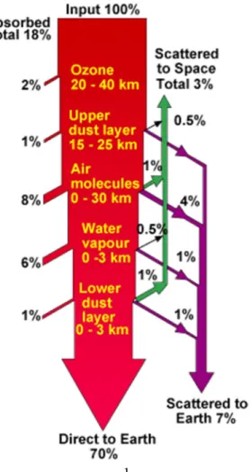
Photovoltaic parameters of the devices different salts dissolved in different acetonitrile (AcCN):propylene carbonate (PC) volume ratios. Photovoltaic parameters of the devices different salts dissolved in different acetonitrile (AcCN):propylene carbonate (EC) volume ratios. First, photons in sunlight strike the solar cell and are absorbed by semiconducting materials such as silicon.
Dye-sensitized solar cells and organic solar cells are included in the third generation of solar cells. In this thesis, electrodeposition, low-cost methods, for the production of solar cell dampers from chalcopyrite was carried out potentiostatically in an electrochemical cell in a non-stirred solution.
Introduction
- History of CIGS solar cells
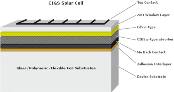
- Structure of CIGS solar cells
- Principle of CIGS solar cells
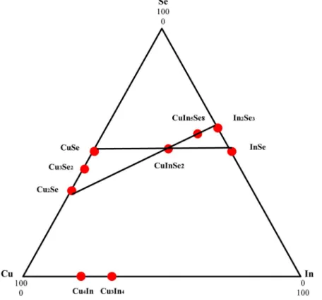
- Material properties
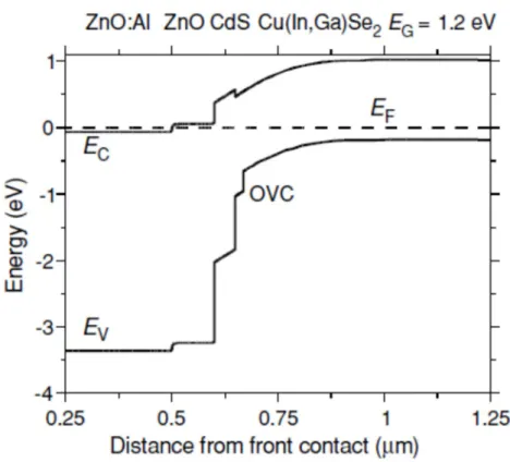
- Device physics – The band diagram
- Absorber growth techniques
The principle of operation of the device is similar to that of conventional crystalline silicon solar cells. In this photogeneration step, the crucial parameter is the band gap energy Eg. of the semiconductor. The band diagram shown in Figure 6 is believed to be a reasonable approximation and shows the inversion of the interface type as required by the above considerations.
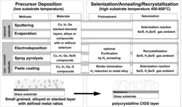
Varying the In/Ga flux ratio during deposition allows fabrication of split-bandgap absorbers. This concept is used to reduce the concentration of indium and the thickness of the absorber layer. Such processes consist of the deposition of a precursor material, followed by thermal annealing in a controlled reactive or inert atmosphere for optimal compound formation by the chalcogenization reaction (Figure 79).
Experiment
Preparation of Mo/glass substrate
In this thesis, electrodeposition was performed potentiostatically in an electrochemical cell in an unstirred solution. Electrodeposition prepared using a three-electrode cell in which the reference electrode was a saturated calomel electrode, the counter electrode was a Pt plate, and the substrate was Mo/glass. The deposition process was carried out in different concentrations of CuCl2, InCl3, GaCl3 and H2SeO3 precursor solution at room temperature.
Electrodeposition of CIGS layer
Electrodeposition prepared using a three-electrode cell in which the reference electrode was a saturated calomel electrode, the counter electrode was a Pt plate, and the substrate was Mo/glass. CuCl2, InCl3, GaCl3 and H2SeO3 as precursor and aqueous solution of LiCl were used.
Results and discussion
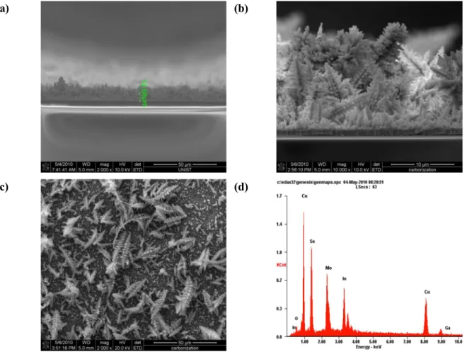
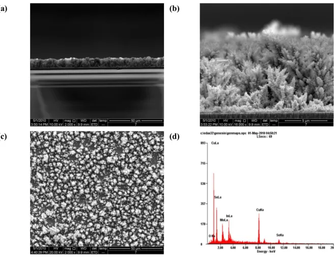
SEM images and EDS analysis
CIGS electrolytically deposited layer morphologies (a) at -0.6 V versus experiment 3) With increasing electrolytically deposition time, the layer thickness was also increased.
XRD results
Conclusions
Dicationic iodide for Dye-sensitized solar cells
History of DSSCs
Structure of DSSCs
Principle of DSSCs
- Electron injection and excited state decay: reaction 1 and 2
- Regeneration of the oxidized dyes: reaction 3
- Electron transport through the mesoporous oxide film: reaction 4
- Recombination of electrons in the semiconductor with oxided dyes or electrolyte
- Electrolyte at the counter electrode: reaction 7
One of the most astonishing findings in DSSC research is the ultrafast injection of the excited Ru complex into the TiO2 conduction band, reaction 2. Although the detailed mechanism of the injection process is still under debate, it is generally accepted that a fast femtosecond component is observed for this type of sensitizer attached directly to an oxide surface.44-47 For the performance of DSSCs, the time scales of the injection process should be compared to the decay from the excited state of the dye to the ground state, reaction 1. This is given by the lifetime of the dye in the excited state, which for typical Ru complexes used in DSSCs is 20-60 ns.44 Interestingly, Durrant and co-workers observed a much slower electron injection in a complete DSSC device with a half-life of approximately 150 ps.
This would then be slow enough for a kinetic competition between electron injection and excited-state dye decay with potential consequences for overall DSSC performance.48. The charge separation of the photoexcited electron and hole occurs by ultrafast injection of an excited dye into the semiconductor oxide. In the case of sensitizers such as N719 and black dye, light absorption is of MLCT (metal to ligand charge transfer) character with the contribution of the sulfur atom of the -NCS group.
Thus, charge separation occurs in the excited state from the π* orbitals of the organic ligand of the Ru complex to the acceptor states in TiO2. The capture of the oxidized dye by the electron donor, usually I-, is in the microsecond time domain. NHE in acetonitrile, 57 which is more positive than the U0(S+/S) of most dyes used as sensitizers in DSC.
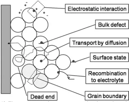
The redox potential of the iodine radical bound to the dye (S · · · I) will have a less positive potential, and the formation of a (S · · · I) complex is therefore a likely first step in color regeneration. Overview of the electron transport process in the electrolyte-infiltrated mesoporous TiO2 electrode of a dye-sensitized solar cell shows the possible origin of the relatively slow diffusion. Traps can be located at the TiO2/electrolyte interface, in the bulk of the TiO2 particles, or at grain boundaries, while electrostatic interactions between electrons and ions in the electrolyte cause ambipolar diffusion, but possibly also trapping.43 (Figure 19) .
The kinetics of the back electron transfer reaction from the conduction band to the oxidized sensitizer follows a multi-exponential time law43 (Figure 20), which occurs on a time scale of microseconds to milliseconds, depending on the electron concentration in the semiconductor and thus the light intensity. response 5).
The progress of DSSCs
Counter electrodes for DSCs with I-/I3- electrolytes can be prepared quite easily by depositing a thin catalytic layer of platinum on a conductive glass substrate. In contrast, for p-type DSSCs, the HOMO level of the photosensitizer should be at more positive potential than the valence band (VB) level of p-type semiconductor. However, dye aggregates can be controlled (H and J aggregates) leading to an improved performance compared to a monomer dye layer. 6) The photosensitizer must be photostable, and electrochemical and thermal stability are also required.
The composition of the electrolyte was adjusted using lower concentrations of lithium or potassium iodide, but did not produce higher conversion efficiencies than the simplest composition. Counter electrodes for DSSCs with iodide/triiodide electrolytes can be prepared quite easily by depositing a thin catalytic layer of platinum on a conductive glass substrate. Without platinum, conductive tin oxide (SnO2:F) glass is a very poor counter electrode and has a very high charge transfer resistance, more than 106 Ω cm2, in a standard iodide/triiodide electrolyte.61 Pt can be deposited by a range of methods such as electrodeposition, spray pyrolysis, sputtering and vapor deposition.
The best performance and long-term stability have been achieved with nanoscale Pt clusters prepared by thermal decomposition of platinum chloride compounds.59 In this case, very. Pt films prepared by other methods, such as electrodeposition and vapor deposition on TCO substrates, were found to dissolve in iodide/triiodide electrolytes and are therefore not suitable as counter electrodes in DSSCs. Kay and Grätzel developed a counter electrode from a mixture of graphite and carbon black for use in DSSCs with the monolithic cell geometry.62 The function of the graphite was both electronic conduction and catalytic activity, while the carbon black with a large surface area was added for a greater catalytic effect .
Poly(3,4-ethylenedioxythiophene) (PEDOT) doped with toluenesulfonate anions shows good catalytic properties for triiodide reduction and was successfully applied in DSSC. 64-66 Films were prepared on TCO substrates and a charge transfer resistance of less than 1 Ω cm2 could be obtained for films thicker than 1 μm. Recently, electrodeposited CoS has been identified as a suitable catalyst for the iodide/triiodide redox couple.67 deposited on a flexible substrate (ITO/PEN) is better than Pt on the same substrate, with a charge transfer resistance up to 1.8 Ω cm2. while thermal Pt on FTO gave 1.3 Ω cm2 using the same ionic liq. electrolyte. Here, it has been investigated to improve the photovoltaic properties of DSSCs, new didactic salts based on ionic liquids were synthesized.
As the size of the cation increases, fewer cations can reach and occupy the TiO2 surface. Therefore, a relatively higher voltage can be expected.68-70 There are some results using newly synthesized salt based on ionic liquids.
Materials
Preparation of electrolytes
Ionic conductivity
Fabrication of dye-sensitized solar cells
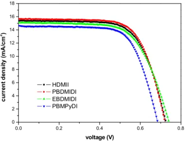
Photovoltaic characterization
Results and discussions
- Dicationic salts in acetonitrile
- Dicationic salts in mixture of acetonitrile (AcCN) and propylene carbonate (PC)
- Dicationic salts in mixture of acetonitrile (AcCN) and ethylene carbonate (EC)
- Dicationic salts in mixture of γ-Butyrolactone and ethylene carbonate
In the case of HDMII, HDMII with a volume ratio of 7:3 (AcCN:PC) has the best efficiency compared to other ratios, but it did not reach the efficiency of the cell with acetonitrile solvent alone. Therefore, bulk cations on the TiO2 surface alleviated the conduction band edge depression by Li+ ions71. 1986, 'The flexibility of electrodeposition for the preparation of CuInS(Se)2 films', Journal of the Electrochemical Society, vol.
1989, 'A voltammetric study of electrodeposition chemistry in the system Cu + In + Se', Journal of Electroanalytical Chemistry and Interfacial Electrochemistry,. 2003, 'Lattice constant depth profile of Cu-depleted surface layer in (Cu2Se)1-x(In2Se3)x evidenced by grazing incidence X-ray diffraction', Journal of Physics and Chemistry of Solids, vol. New rapid thermal processing for CIS thin film solar cells', Proceedings of the 23rd IEEE Photovoltaic Specialists Conference, New York, 1993, pp.
2006, 'Dye-Sensitized Solar Cells with 11.1% Conversion Efficiency', Japanese Journal of Applied Physics, Part 2: Letters, vol. 2002, 'Photoinduced ultrafast injection of dye electrons into a semiconductor from non-thermalized and thermalized donor states', Journal of the American Chemical Society, vol. 2006, 'High Molar Extinction Coefficient Heteroleptic Ruthenium Complexes for Thin Film Dye Sensitized Solar Cells', Journal of the American Chemical Society, vol.
2009, 'Parameters affecting electron injection efficiency in dye-sensitized solar cells', Journal of the American Chemical Society, vol. 2005, 'Charge separation and efficient light energy conversion in sensitive mesoscopic solar cells based on binary ionic liquids', Journal of the American Chemical Society, vol. 1997, 'An iodine/triiodide reduction electrocatalyst for aqueous and organic media', Journal of the Electrochemical Society, vol.
2004, 'Behavior of the I-/I3 redox reaction at the poly(3,4-ethylenedioxythiophene) counter electrode in dye-sensitized solar cells', Journal of Photochemistry and Photobiology A: Chemistry, vol. 2009, 'CoS replaces Pt as efficient electrocatalyst for triiodide reduction in dye-sensitized solar cells', Journal of the American Chemical Society, vol. 2004, 'Dye-Sensitized Solar Cells: Enhancement of Spectral Response by Co-Structure', Journal of Photochemistry and Photobiology A: Chemistry, vol.