Severe electrolyte decomposition at the Na metal electrode leads to the formation of a resistive and non-uniform surface film, leading to dendritic Na metal growth. To control the Na metal electrode-electrolyte interface for high performance Na metal batteries, considerable efforts have been made to find electrolyte systems that are stable at the Na metal electrode. Finding new electrolyte systems that are stable at the Na-metal electrode and possess high oxidation durability at high-voltage cathodes is necessary for the development of high-performance Na-metal batteries.
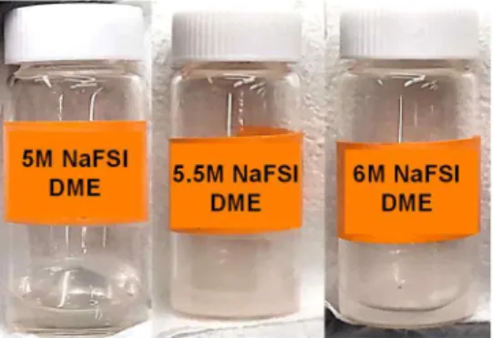
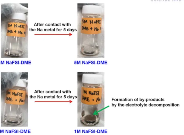
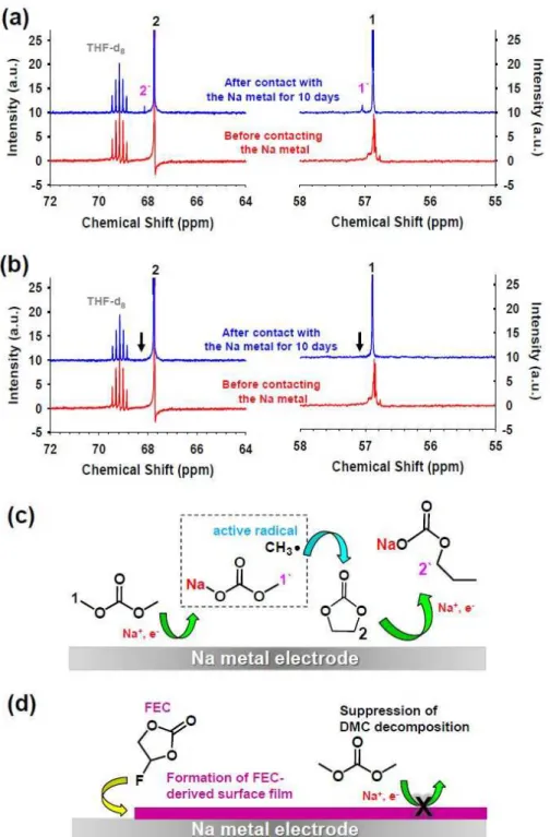
Schematic representation of (c) formation of decomposed products from the reaction between DMC and Na metal and (d) suppression of DMC decomposition by the addition of 5 wt% FEC, which can create a protective surface film on Na metal. Photograph of Na metal electrodes after contact with 1M NaFSI-DME or 5M NaFSI-DME for 5 days. The utilized capacity of the Na metal electrode was 5.0 mAh. a) Galvanostatic cycling of symmetric Na/Na cells during 600 cycles under the condition of 0.5 h time cut-off at a current density of 0.0028 mA cm−2 after precycling at a current density of 0.0014 mA cm−2 . b) Enlarged region showing voltage profiles for cycles 561 to 570.
The inset photos show Na metal electrodes and GFF separators extracted from Na/Na4Fe3(PO4)2(P2O7) cells with 1 M, 4 M or 5 M NaFSI-DME after precycling. For comparison, the voltage profiles of the Na4Fe3(PO4)2(P2O7) cathode with 1 M NaPF6-EC/PC (5/5) and photos of the found Na metal electrodes and GFF separators are included.
Demand for Na metal batteries
Problems of Na metal batteries
13C NMR spectra of (a) electrolyte with DMC addition and (b) electrolyte with DMC + FEC addition before and after contact with metal Na for 10 days without applied potentials. Schematic representation of (c) formation of decomposition products by the reaction between DMC and Na metal and (d) inhibition of DMC decomposition by the addition of 5 wt. % FEC that can create a protective surface film on Na metal.14 .
New electrolyte systems : highly concentrated electrolytes
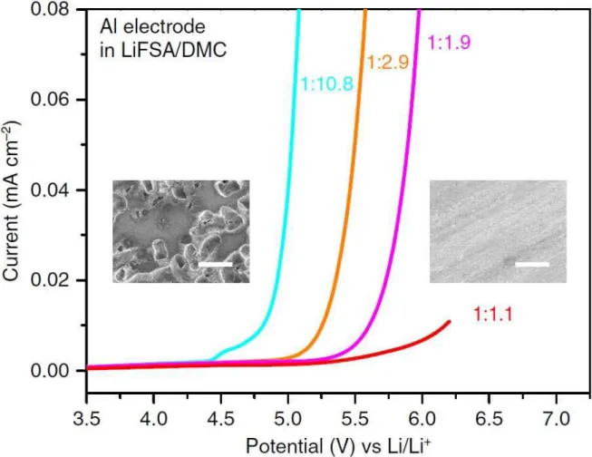
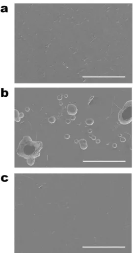
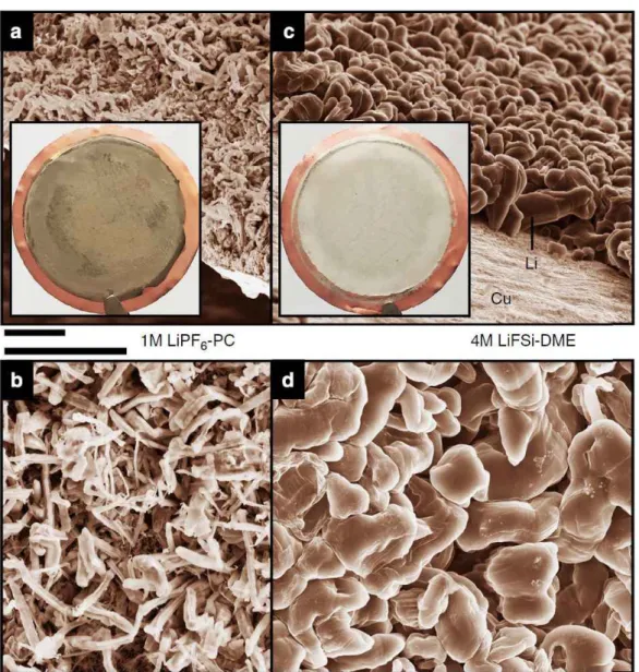
Moreover, we report for the first time that Na metal anodes coupled to high-voltage cathodes with high charge switching voltages of 4.3 V vs. Na/Na+, Na4Fe3(PO4)2(P2O7), and Na0.7 (Fe0 .5Mn0). 5)O2, exhibits superior electrochemical performance with this ultraconcentrated electrolyte than with the conventional diluted 1 M ethylene carbonate NaPF6 (EC)/PC (5/5, v/v) electrolyte. SEM images of Li metal morphologies after deposition on Cu substrates in different electrolytes. LSV of an aluminum electrode at different concentrations of LiFSA/DMC electrolytes in a three-electrode cell.
The insets are scanning electron microscopy images of the Al surface polarized in the dilute 1:10.8 (left of panel) and superconcentrated 1:1.1 (right of panel) electrolytes. Many corroding pits cover the surface of the Al electrode polarized in the dilute electrolyte, showing a severe anodic Al solution. In contrast, no corroding pits appear on the surface of the Al electrode polarized in the superconcentrated electrolyte, indicating a good inhibition of anodic Al dissolution.
Experimental
Characterization
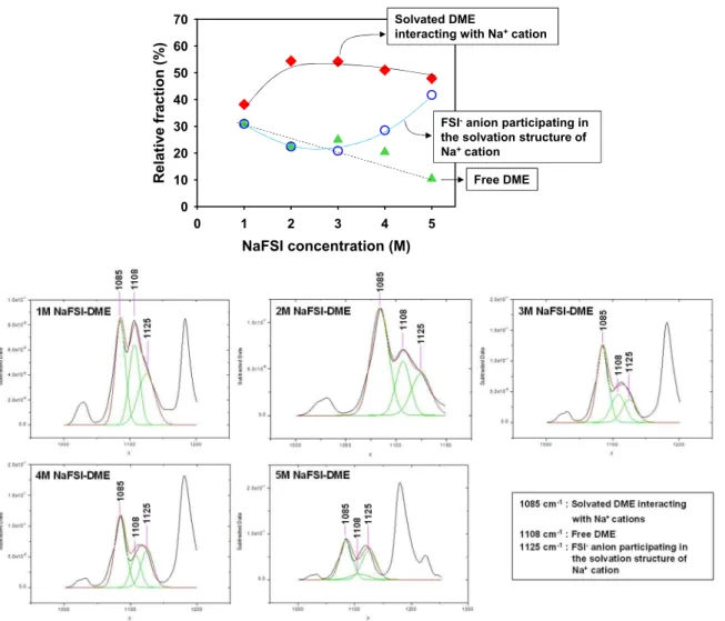
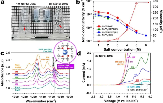
The ionic conductivity and viscosity of the electrolytes at room temperature were measured using an Oakton CON 11 standard conductivity meter and a Brookfield viscometer (LVDV-ll+P) respectively. The attenuated total reflectance-Fourier-transform infrared (ATR-FTIR) spectra of the electrolytes were recorded by reflectance measurements obtained using a Varian 670-IR spectrometer with a spectral resolution of 4 cm−1 under a nitrogen atmosphere. Scanning electron microscope (SEM; . JSM-6700F, JEOL) images of Al working electrodes after linear sweep voltammetry (LSV) measurements and the Na metal plated on the Cu substrate were recorded using an FEI Nanonova 230.
During the acquisition of the SEM image of the Na metal plated on the Cu substrate, an energy dispersive spectrometer (EDS) was used to determine the type of chemical components. Each electrode was rinsed with DME to remove residual electrolyte and then dried at room temperature.
Electrochemical tests
Result and Discussion
- Three mechanisms of improved oxidation durability of 5M NaFSI-DME
- Electrochemical performances of Na/SS cells and analysis
- Electrochemical performances of Na/Na symmetric cells and analysis
- Electrochemical performances of Na/Cathode cells and analysis
Interestingly, the anodic limit of 1 M NaFSI-EC/PC was analogous to that of 1 M NaFSI-DME. Indeed, many pits were observed on the Al surface produced by Al corrosion in 1 M NaFSI-DME (Figure 8b). This result suggests that conventional diluted 1M NaFSI-DME undergoes severe degradation at the Na metal.
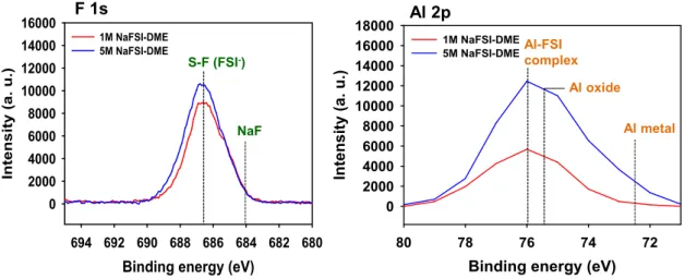
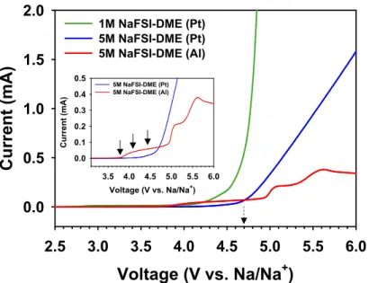
On the contrary, there was no observable color change of the Na metal stored in 5 M NaFSI-DME. This is a clear evidence for the low decomposition tendency of 5 M NaFSI-DME at the Na metal electrode. Anodic limits of 1M NaFSI-DME and 5M NaFSI-DME on a Pt electrode at a scan rate of 1 mV s-1.
This phenomenon is mainly due to the high viscosity of concentrated NaFSI-DME electrolytes (Figure 5b). More concentrated NaFSI-DME electrolytes led to significantly improved ICEs for Na plating/stripping on the SS working electrode. The impact of ultra-concentrated 5 M NaFSI-DME on cycling stability at high C2 speeds is shown in Figure 12d.
The use of the 5 M NaFSI-DME electrolyte clearly results in dramatically improved speed capability compared to the conventional diluted 1 M NaPF6-EC/PC (5/5) electrolyte. A relatively strong carbon (C) signal produced by the decomposition of EC and PC solvents appeared for the Na deposition on the Cu substrate with 1 M NaPF6-EC/PC (5/5) compared to 5 M NaFSI-DME -electrolyte. Importantly, a very stable voltage profile and low overpotential for plating/stripping of Na metal on the Na metal electrode were observed with the ultra-concentrated 5 M NaFSI-DME electrolyte after 600 cycles at a current density of 0.0028 mA cm− 2.
This finding indicates that the interfacial structure formed in the 5 M NaFSI-DME electrolyte effectively assists. This finding shows that the low ionic conductivity of the ultraconcentrated 5 M NaFSI-DME electrolyte does not hinder the electrochemical reactions of the Na4Fe3(PO4)2(P2O7) cathode. The cell with the 1 M NaFSI-DME electrolyte showed significant overcharging with a longer length of the voltage plateau at about 3.2 V vs. Na/Na+ and a significant color change of the Na metal electrode and a glass fiber filter (GFF) separator cause (Figure 18).
After reaching 4.0 V vs. Na/Na+, overcharging with a long voltage plateau at about 3.9 V was observed in the Na/Na4Fe3(PO4)2(P2O7) cell with 4 M NaFSI-DME. The excellent electrochemical performance of ultraconcentrated 5 M NaFSI-DME is not only with the phosphate.
Conclusion
Na-ion batteries, recent advances and current challenges in becoming low-cost energy storage systems. L.; Improved surface stability of C+MxOy@Na3V2(PO4)3 prepared by ultrasonic method as cathode for sodium ion batteries. Carbon-coated Na3.32Fe2.34(P2O7)2 cathode material for high-rate, long-life sodium-ion batteries.
NaN3 addition, a strategy to overcome the problem of sodium deficiency in P2-Na0.67[Fe0.5Mn0.5]O2 cathode for. Electrochemical properties of ultrafine Sb nanocrystals embedded in carbon microspheres for use as Na-ion battery anode materials. A Novel rGO Overcoated Sb2Se3 Nanorods Anode for Na+ Battery: In Situ X-ray Diffraction Study on a Live Sodiation/Desodiation Process.
Cyclic carbonate-based electrolytes improving the electrochemical performance of Na4Fe3(PO4)2(P2O7) cathodes for sodium-ion batteries. Interfacial architectures based on a binary additive combination for high-performance Sn4P3 anodes in sodium-ion batteries. Highly Stable Linear Carbonate-Containing Electrolytes with Fluorethylene Carbonate for High-Performance Cathodes in Sodium-Ion Batteries.
Electrochemical Na insertion and solid electrolyte interphase for hard carbon electrodes and application to Na-ion batteries.