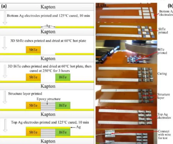
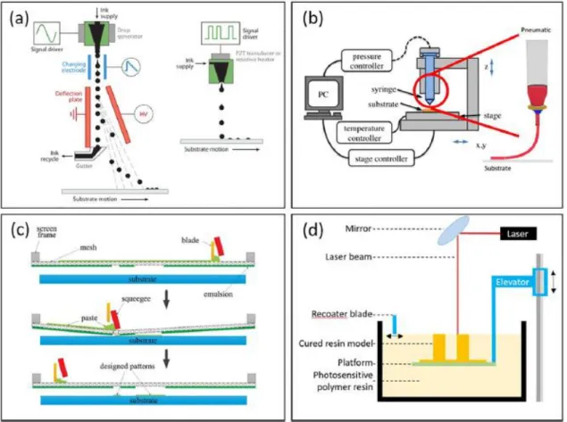
Schematic representation of the manufacturing process via screen printing. a) Image of the planar TEG for the flexible thermoelectric films and (b) schematic illustration of wearable TEG by Bae et al. SEM images of the TE materials (a) without and (b) with the Sb2Te3-based inorganic solder after heat treatment. A linear adjustment of resistance as a function of distance between TE leg patterns via transmission line method.
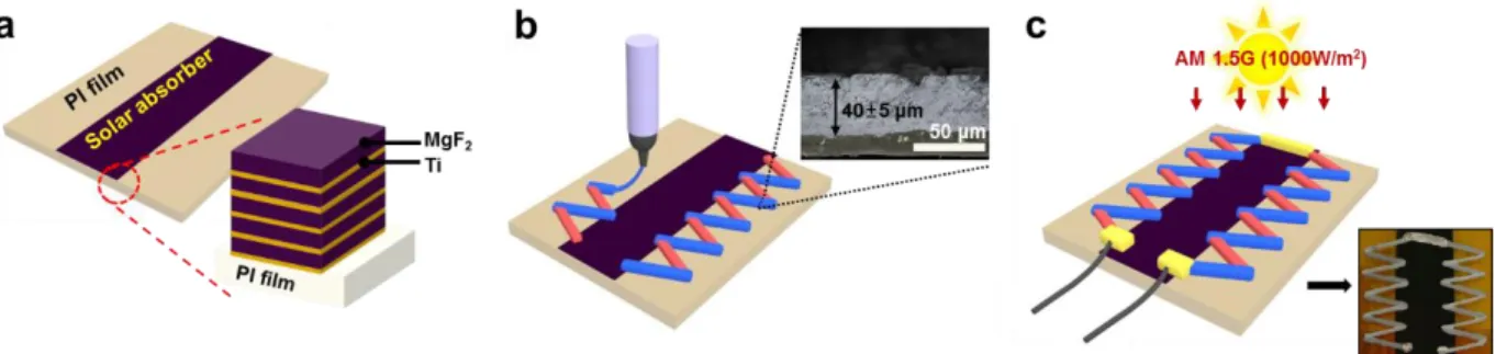
The relationship between the voltage and the ∆T. b) Voltage and power as a function of ΔT. a) Simulated results of the amount of heat through the solar absorber depending on the Ti/MgF2 thickness. Schematic diagram of the production process for the W-STEG and a process for (a) depositing a Ti/MgF2 multilayer solar absorber on flexible PI substrate, (b) dispenser printing of thermoelectric ink on PI substrate with a solar absorber and (c) measuring W-STEG power under AM 1.5G condition. The cross-sectional SEM image of the parylene C-coated TE legs, showing the microcrack filling.
Voltage-time curve showing the instantaneous response to light and the maintenance of voltage over time.
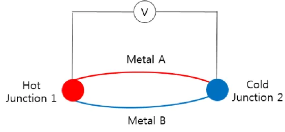
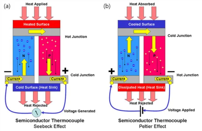
Basic principle of thermoelectricity
- Thermoelectric effect
- Characterization of thermoelectric generator
- The strategies to enhance thermoelectric performance
- Characteristic of Bismuth-Telluride material
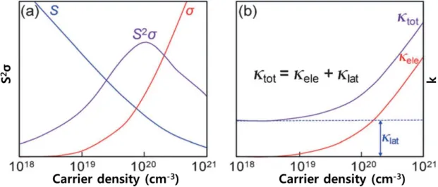
The performance of the thermoelectric device is directly proportional to the ∆T and dimensionless figure of merit; ZT, which is generally defined by. 𝐴 (1.5), where ρ is the electrical resistance, L is the length of the thermoelectric leg, and A is the cross-sectional area of the leg [3]. To maximize PF, the development of materials with new nanoscale electronic structure and doping of the thermoelectric material is crucial.
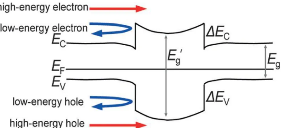
Increasing the relaxation times increases the differential slope of the conductivity, which further improves the Seebeck coefficient. Bismuth telluride has a rhombohedral structure with perpendicular stacking along the c-axis of the sequence.
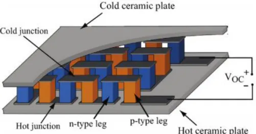
Various types of thermoelectric generator
- Conventional thermoelectric generator
- Printing-based thermoelectric generator
- Flexible/wearable thermoelectric generator
- Solar absorber-based solar thermoelectric generator
Interface heat transfer is used to calculate the temperature and radiation intensity fields. SEM images of n-type diffuser (BTS) and p-type (BST) printed TE materials (a) without and (b) with Sb2Te3-based sintering additive after sintering at 450°C. To measure electrical conductivity, silver paste was painted on both ends of the TE legs.
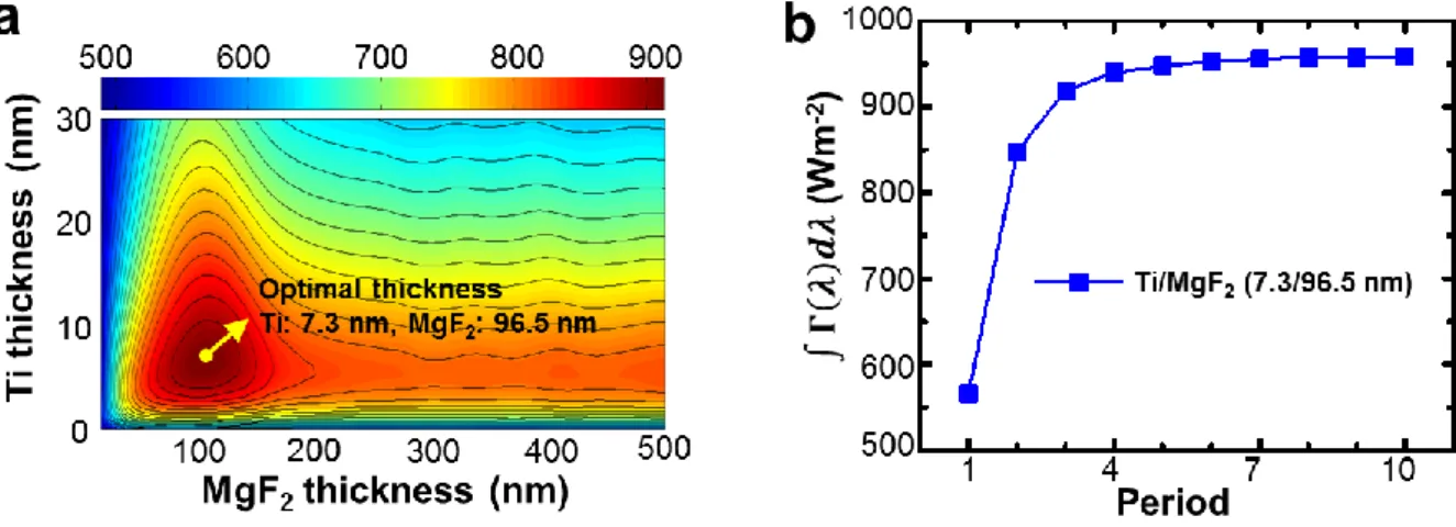
The schematic illustration of the measurement setup was demonstrated in the inset of the figure. We calculated the area (∫ 𝜦(𝝀)𝒅𝝀) of the solar absorption spectrum according to the thickness of each layer, Ti and MgF2. The area of the solar absorption spectrum reflects the total solar absorption, which directly relates to the heat generation of the solar collector.
T was created from the hot side of the local solar absorber and the cold side of the PI substrate. Therefore, depending on the length of the leg TE on the side of the table PI in. The length of the TE leg was increased from 5 to 15 mm, and the output power characteristics of the W-STEG with 10 pairs of TE legs were measured (Figure 2.22).
Due to the layered crystal structure, BiTe materials are known to be very brittle [59]. In a real-world application of wearable TEG, the stiffness and flexibility of the device must be compromised. As seen in the cross-sectional SEM image of the BiTe leg (Figure 2.27), microcracks are present on the BiTe surface.
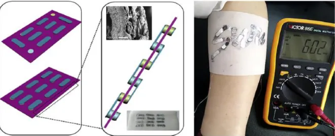
Wearable solar thermoelectric based on Bi-Te based ink printing technique
Experimental methods
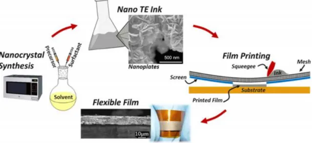
- Synthesis of Bi 2 Te 3 -based thermoelectric ink
- Dispenser printing process of the thermoelectric leg
- Characterization of the thermoelectric generation
- Simulation of the structure of Ti/MgF 2 superlattice
- Simulation of the heat flux on the substrate with Ti/MgF 2 superlattice
The Seebeck coefficients (α) of the TE legs were measured as a function of Tacross the leg by a home-built TE measurement setup as shown in fig. To optimize the Ti/MgF2 multilayer, the total absorbed energy was calculated as a function of the thickness of the Ti/MgF2 superlattice. We also assumed that sunlight hit the surface of the substrate and the absorbed energy is converted into heat.
It is important to study the rheological behavior of the TE ink, as the viscoelasticity of the ink has a significant effect on the. The Sb2Te3 binder in this work acts as a sintering aid, further improving the electrical conductivity of the TE material. XRD peaks of each temperature are consistent with the previously reported peaks of the single crystal sample [41,42].
Since there is no significant difference in solar absorber performance above the stack number value of five, there were five periods. The data showed a noticeable difference in electrical resistivity up to 150 cycles depending on the presence of Parylene C. The Parylene C coating allows for uniform stress distribution, thus improving the flexibility of the substrate.
We can expect an increase in the efficiency of the device by ensuring the maximum structure of the temperature difference in relation to the heat flow. Comparison graph of the temperature difference according to the wtepwise strategy for increasing the temperature difference in a plane base.
Characterize of thermoelectric ink
- Viscosity analysis of thermoelectric ink for printing
- SEM and XRD analysis for Sb2Te4-solder effect on thermoelectric ink
- Thermoelectric properties of the dispenser printed leg
Ti/MgF 2 multilayer thin film based solar absorber
- Structure optimization of Ti/MgF2-superlattice based on the FDTD simulation
- SEM and optical analysis of Ti/MgF2-superlattice
- Heat flux modeling
- Ti/MgF 2 superlattice dimension optimization based on heat flux simulation
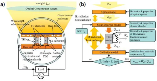
In this study, a multilayer metal/dielectric solar absorber structure was introduced to improve the thermal gradient. The solar absorption spectrum was obtained by multiplying the solar radiation spectrum with the calculated absorption spectrum for a particular multilayer film [48]. As the stack period increases, so does the number of metal layers involved in absorption, and then the absorption capacity of the solar absorber is saturated close to the ideal 1 absorption of the sun (1000 W/m2).
As a result, an optimal structure consisting of a thickness of 7.3 nm Ti and 96.5 nm MgF2 five-period layers was obtained, and it turned out that period is enough to absorb 95% of light (Figure 2.11). a) Simulated results of the amount of heat absorbed by the solar absorber as a function of Ti / MgF2 thickness. To obtain the total solar absorption spectrum, the solar irradiance was multiplied by the measured absorbance spectrum. By performing a simulation based on heat transfer analysis, we calculated the three-dimensional temperature distribution of the device for a steady-state solution.
The lengths of the solar absorber and the PI substrate were 4 cm × 2 cm and 4 cm × 4 cm2, respectively, and the total heat input to the substrate was 1.6 W, which is equal to the steady-state power output in the law of energy conservation. is absorbed onto the PI substrate. Heat is transferred from the solar absorber, which is the hot side, to the PI substrate. Since the absorber is activated at a high temperature gradient between two substrates, the temperature distribution of the two substrates is very important. 2.17 simulation and experimental results show the temperature distribution with respect to the width of the solar absorber.
Solar absorbers obtained by FDTD simulations of structural optimization are more reliable and operational. The sudden temperature difference at the edge is because the thermal resistance of the PI is much higher than that of the solar absorber, so the thermal resistance of the PI increases, which promotes a rapid temperature change. In addition, the heat absorbed by the solar energy increases as the width of the solar absorber increases, but the heat fluxes of convection and radiation decrease. a) Simulated results of the temperature gradient with respect to the width of the solar absorber.
Fabrication of wearable solar thermoelectric generator
- Device structure optimization
- Thermal imaging of the W-STEG
- The characterization of W-STEG
This means that ∆T of the W-STEG is almost saturated for widths of absorbent greater than 10 mm. However, the total internal resistance value of the W-STEG increased as the TE leg length also increased, the optimum length of the TE leg is selected by the output power characteristics and the relative TE leg length. As leg length increases from 10 to 15 mm, the resistance of the ten pairs of TE legs increased by 50%, but ΔT did not increase as much, which reduced the output.
For visualization of the W-STEG with temperature difference, a self-heating solar absorber (under the condition of AM 1.5 G), infrared image of the working W-STEG was obtained. The highest and lowest temperatures of the TE legs were about 46.7 °C and 35.3 °C, respectively, when the whole device was exposed to radiation, and the output voltage and power were measured at 33.23 mV and respectively 1.45 µW. It was assumed that the temperature on the cold side is increased due to the absorption of light by the BiTe legs, heat conduction and the Joule heating by internal resistance.
T increased dramatically to 20.9 K, with the maximum and minimum temperatures of the TE arms being approximately 46.6 °C and 26.7 °C, respectively, due to the extreme decrease in temperature at the end of the TE arm corresponding to the cold side. The W-TEG fabricated in this study has a ΔT of 20.9 °C and, to our knowledge, the highest ΔT of a WTEG. In this study, parylene C was deposited on the device surface to a thickness of ~1 μm to increase the flexibility of the WTEG without reducing its thermoelectric properties.
Parylene C does not cause thermal deformation of the device as it is conformally deposited on rough surfaces at room temperatures [62]. This is one of the main disadvantages of WTEG technology in which heat is induced by the surface of the human body. And the absorption of the structure was 97.53% at the wavelength of 520 nm which has the highest peak of solar radiation.
Application of wearable solar thermoelectric generator
- The process of thermoelectric painting
- Flexibility of the W-STEG
- Application of wearable solar thermoelectric generator
- The optimum temperature difference considering the heat flux
Conclusion
The proposed portable solar TEG can generate a high value of ΔT up to ~ 21 °C through a locally deposited solar absorber on the substrate. The TE legs were printed on a flexible substrate, which has similar electrical conductivities of ~ 25,000 S/m, and the Seebeck coefficients of -116.4 and 166.4 μV/K, respectively. The output characteristics of 10 pairs of TE legs with Voc exposed to the irradiation condition at AM 1.5G were 55.15 mV and of 4.44 μW.
The ΔT value between the hot solar absorber and the cold PI edge is as high as 20.9 °C, the highest ΔT of all portable TEGs reported to date. Furthermore, wearable CCGTs can be easily mounted on various surfaces exposed to sunlight, such as clothing, windows and exterior walls, and are expected to be useful in a variety of applications such as self-driving wearable electronics. Parts of this chapter have been published in the article “Portable thermoelectric solar generator powered by unprecedented high temperature difference” Nano Energy.