Recommended by the Scientific and Technical Council of the University Authors: Buzauova T.M., Sherov K.T., Algazy Zh., Turusbekova A.S. Severe operating conditions of mining equipment cause intense wear of the working surfaces of the parts of the main components and mechanisms.
ANALYSIS OF THE RESEARCH
Object of study
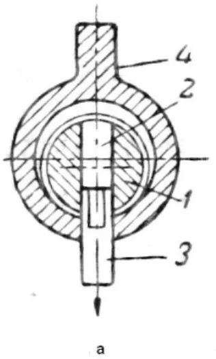
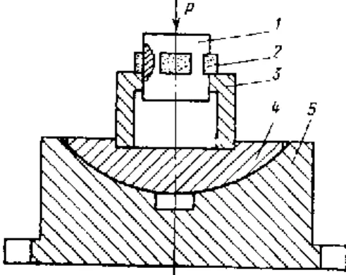
An eccentric is a thick-walled cylindrical part with an offset center of the axis - eccentricity: l up. The eccentric unit is subjected to vibrations, shocks and variable loads during the operation of the crusher.

DETERMINATION OF THE WEAR
- Features of the flow of abrasive wear in the coupling
- Types of abrasive wear of machine parts
- Abrasive wear processes
- Formation of the processes of materials wear
- Determination of wear in coupling
The type of wear is determined by the nature of the interaction of abrasive particles with the surface layer of the material. The process of abrasive wear is unequivocally determined by the type of destruction of the surface layer and softening of the material.
ANALYSIS OF EXISTING METHODS
- Ways to restore parts
- Restoration of machine parts and mechanical and mechanical
- Restoration of parts by welding and overlay welding
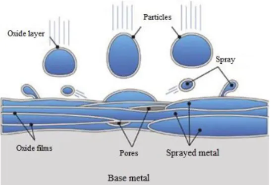
- Restoration of parts by metallization
- Technological and physical characteristics of metallization
The quality of the substrate largely depends on the condition of the surface to be repaired. Porosity provides a margin on the surface of the oil, necessary to maintain a standing oil film.
ANALYSIS OF STATISTICAL DATA
Overview of statistical data analysis methods
It is sufficient to limit ourselves to considering a small number of the most correlated linear combinations from each set. This type of analysis is multidimensional, because it uses several features of the object, the number of which can be arbitrarily large. Therefore, the main purpose of factor analysis is to reduce the number of variables based on the classification of variables and the definition of the structure of the relationships between them.
Indicators of the similarity of objects in practice can be the distance or the degree of communication between them. Despite the fact that there are many similarities in the nature of the questions studied, the methods of multidimensional scaling and factor analysis have a number of important differences.
STUDIES OF THE METHODS OF THERMAL
Indicators of surface quality in the processing of thermofriction
- Depth of distribution of plastic deformation
- Surface Roughness
From the latter it follows that hh affects the hardness of the material that is processed directly during the cutting process (dynamic hardness) and is measured after stopping the process [70]. The parameters and working conditions characteristic of modern mining machines place high demands on the surface quality of mating parts. Thus, the wear resistance of the part depends on the quality of the surface layers.
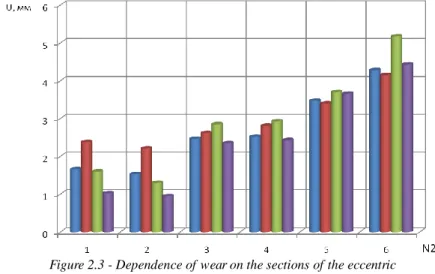
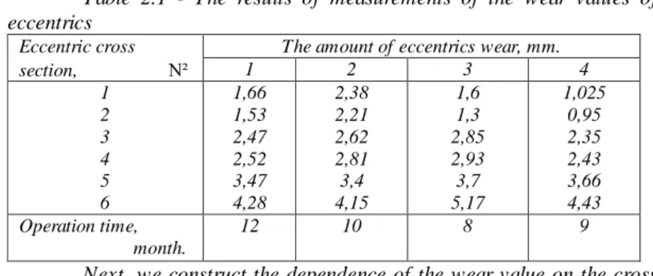
Improving the quality of rubbing surfaces increases the service life of the machine, prolongs their durability. Based on the given state of the question and the results of the.
Methods of conducting research Thermofriction processing (TFP)
- Hardness Measurement
- Roughness measurement
- Temperature measurement
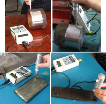
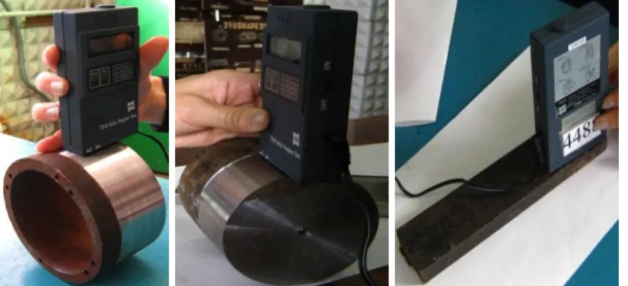
The hardness of the treated surface was determined with the MET-U1 device according to the Vickers method. At the moment of impact, a carbide ball placed at the end of the impact touches the measured surface. The principle of operation of profilometers is based on the measurement of surface irregularities by probing with a diamond needle.
To measure the values of the electromotive force ЕАБ between points 3 and 4, they connect a galvanometer or potentiometer. In addition, the reliability of the obtained data was determined by comparison with the results of other researchers.

Methods of thermal friction processing of cone crusher parts
To process the results of the most important dependencies, the method of mathematical statistics was used, it was regression analysis. In addition, the movement of the tool provides mechanical removal and extrusion of metal particles from the processing area. Let's look in detail at the essence of the method of thermofriction cutting-strengthening processing of cylindrical surfaces [65, p.
On the surface of the friction disc, which is provided with special grooves on the circumference, a coolant is continuously supplied with the help of a tube 4 directly to the cutting zone. In this case, the cutting fluid, which falls on the surface of the friction disc, spreads over it, which cools the friction disc and increases its speed, through special grooves directly on the contact area where the cutting process takes place.

Experimental study of the quality of the surface layer
Also, the processes that occur in the contact disc core depend to a large extent on the value of the peripheral speed. And also cooling the surface directly during cutting leads to an increase in the temperature gradient due to the localization of the thermal field. A change in the hardness of the cutting surface and the layers adjacent to it can occur for two reasons.
This can be done by heating the material to a very high temperature and cooling it quickly directly in the process. During the TFP process, all these phenomena can occur within the range of specified modes.

Calculation of heat distribution in the eccentric using TFP
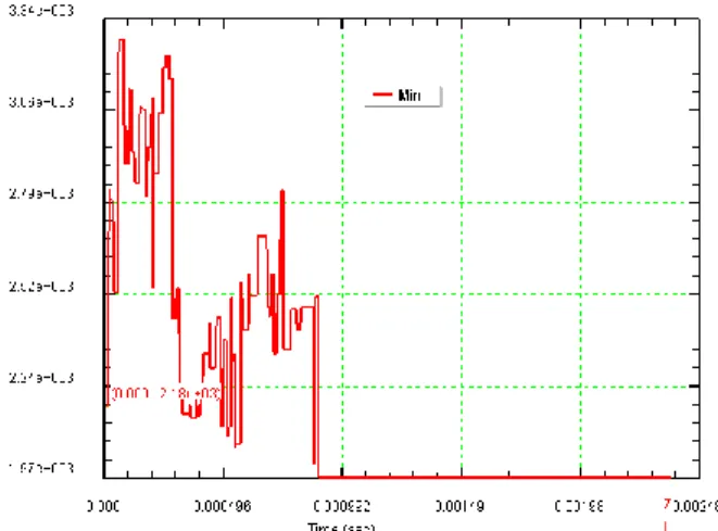
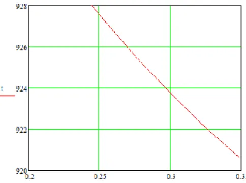
By varying the velocity at the periphery of the disk, it is easy to set the necessary Vu by means of an artificial thermocouple to ensure conditions (5.2). 5.9) Since the areas of the inner and outer surfaces of the eccentric are different, the values of the heat flux densities q1 and q2 are also different. The dependences obtained in figures 5.17-5.23 show that the temperature drop in the body of the work piece is mainly due to the thermal conductivity coefficient of the material and has a clear linear function.
At the same time, it should be noted that the dynamics of temperature drop is higher than that of materials during normal heating. A sharp temperature drop is determined by the time of exposure to heat, which is approximately equal to the length of the friction disc tooth during thermofriction processing, that is, the time of friction friction of each individual tooth segment.
EXPERIMENTAL STUDIES
- Study of the dependence of wear on the operating modes
- Doing the experiment and description of the laboratory setup
- Statistical planning of experiments. Planning an experiment to
- Planning an experiment
- Getting a mathematical model of the object
- Testing the significance of model coefficients
Traditional research methods used in the field of machining (single-factor experiment) do not provide for finding the experimental error, nor for verifying the reliability (adequacy) of the obtained dependencies. For convenience, we will use the regression equations, presented in the form of the formula (6.6). The value of b0 is therefore equal to the average value of the optimization parameter yv.
The variance of the optimization parameter s2 (у) is the arithmetic mean of the variances of all n different experimental variants (average variance). Cochren's criterion is the ratio of the maximum variance to the sum of all variances.
MODELING OF PROCESSES OF THE
Selection of the method of automated analysis of TFP
Steady-state processes of various physical natures are described by equations of the elliptic type. To simplify the calculation of the problem, the finite element method can be implemented using the DEFORM 3D program. In addition, the user of the DEFORM™ - 3D system has the ability to adjust the raster density and finite element size ratio in a "manual" mode.
Using the DEFORM™ - 3D system, it is also possible to simulate separation and mechanical processing operations. Development and technical support of the DEFORM™ - 3D system is provided by Scientific Forming Technologies Corporation (SFTC).
Planning of machine experiments in modeling
If, at a significant amplitude of changes in some component of the model parameter vector, the response changes slightly, it means that the accuracy of the representation of this component in the SM does not play a significant role. In addition, this component will not be used as the main one in planning simulation experiments. If the model's response turns out to be very sensitive to changes in a component of the vector, then this indicates the need to represent it in the model with the highest possible accuracy.
Development of the model in the preprocessor
After opening the preprocessor, set the SM measurement units, mark the name of the task/project and the type of process. In the waiting diameter of the working sample, the user can fit any single-level model or solve the problem in the form of a curve. Simulation control setup including number of steps (1000), save steps (25) and cut length (3.5 mm) to start running the Lagrange function.
Although we described the length of the number of steps, the modulator will choose a measure based on the length of the track. Geometric model of the tool and the work sample made in the CAD system, and made in STL form.
Prototyping the original geometric forms in STL format
In addition, each facet must have two common vertices with each of its adjacent facets. It should not be more than 1/3 of the smallest radius, otherwise it will not be possible to accurately describe the shape. The curvature of the surfaces is sufficient, while at the same time there is a lack of elements on the collar (one element per 1/12 circle).
When modeling an eccentric with a number of elements of 10,000 (Figure 7.4), the hole accurately describes ø10mm, the inner hole for the eccentric is described with a small defect on the side of the wall with a large thickness, but the deviation of the correct The curvature is about 1/20 and does not exceed 5%, which is very acceptable. From the proposed models we choose a number of elements equal to ≈10,000, which quite accurately describes the hole ø10 mm, the inner hole for the eccentric is described with a small defect on the side of the wall with a large thickness, but the deviation of the correct curvature is about 1/20 and not greater than 5%, which is quite acceptable.
Output Management
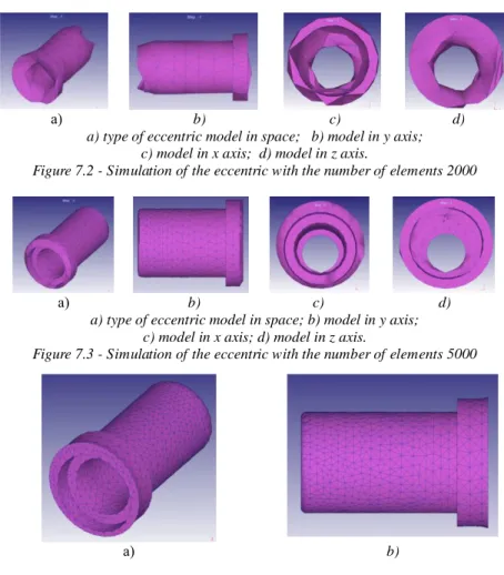
When modeling an eccentric with the number of elements 2000 (Figure 7.2), it can be said that only the largest surface (outer) is described correctly, the remaining surfaces are described incorrectly. The deviation from the true dimensions due to the size of the elements is at least a point of the order of 9/10, which is completely unacceptable for calculations. When modeling an eccentric with the number of elements 5000 and 10000 (Figure 7.3), all surfaces are described correctly except the ø10mm hole.
In other systems, a different set of parameters are used, which in turn are related to other factors that also affect the quality of the output and the functionality (or limitations) of each specific system. In addition, the ability of the system to display STL files for building models is worth noting.
Support for STL output in CAD systems
As we have said, output in ASCII codes is included in the core of the system. The first thing you need to do is to mention the Proximity Tolerance parameter, which allows you to set the precision of the mating surfaces. You can control the Facet Deviation parameter, which defines the maximum distance from the surface in the front plane of the facet that aligns with this surface.
The parameter values can be selected from a set of predefined parameters depending on the size of the prototyping machine. The Conversion Tolerance parameter limits the distance between the model surface and the facets that approximate it.
Obtaining results modeling of the TFP process
The magnitude of the maximum strain is sufficient for plastic deformation of the material (Figure 7.13). Analysis of the technological capabilities of the methods of thermofriction metal processing // Tools and technology. Analysis of methods and methods of thermofriction processing // Science Bulletin of the Kazakh Agrotechnical University.
Investigation of the thermal regime in the heating zone during the thermofriction section with high frequency cooling. Control of the average temperature in contact with the thermofriction segment with high-frequency cooling // «Ізденис-Поиск».