This operating manual describes the structure, functions and use of the product and helps you operate the product as intended. These instructions are intended for a qualified person and must be read carefully by anyone who installs, commissions, operates, maintains, disassembles or disposes of the device. This manual contains all information about the CANopen Gateway in the BL20-ECO (BL20-E-GW-CO) product line.
The following chapter contains a brief description of the BL20, a description of the fieldbus system used, precise information about the function and structure of the fieldbus-specific CANopen-gateway, as well as all bus-specific information about connection with automation equipment, maximum system. - expansion of etc. Bus-independent I/O modules of the BL20 system as well as all bus-independent information such as mounting, labeling etc. In addition, the mentioned manual contains a brief description of I/O-ASSISTANT, the project planning and configuration software tool for Turck I/O systems.
We strive to make these instructions as informative and clear as possible. You can access the product database at the following address: www.turck.de/produkte.
Intended use
Turck accepts no liability for damages caused by failure to observe these warnings and safety notices.
General safety instructions
CANopen
Communication
Network Management Messages
After "switching on", each CANopen device is in the "Initialization" state and automatically changes to the Pre-Operational state. If the master NMT has set one or more nodes to the Operational state, they are allowed to transmit and receive PDOs. In the substate reset application, the parameters of the manufacturer-specific profile area and the standardized device profile area are set to their power-on values.
In the Reset Communication substate, the parameters of the communication profile area are set to their enable values. The Heartbeat protocol and Node Guarding are for error checking and signal the presence of a node and its status. The Heartbeat message is a periodic message from the node to one or more other nodes.
A device sends the startup message to indicate to the NGV master that it has reached the state pre-operational. The startup message has the same identifier as the Heartbeat object, but its data content is null.
Service Data Objects (SDOs)
This happens every time the device starts up, but also after a power failure during operation.
Process Data Objects (PDOs)
To initiate simultaneous sampling of input values for all nodes, a periodically transmitted Sync message is required. Cyclic transmission means that the node waits for the Sync message, after which it sends its measured values. The time period between synchronization messages is defined by the communication cycle period, which can be reset by a configuration tool for the application devices during the startup process.
There may be a timing noise in the transmission from the Sync Producer due to some other objects with higher previous identifiers or from a frame being transmitted just before the Sync message. Message Synchronized in a single CAN frame with identifier 128 by default. The Emergency message is triggered by the occurrence of an internal device error situation and is transmitted by an Emergency producer to the corresponding application device.
As long as no new errors occur on a device, no other Emergency messages can be transmitted. CANopen defines several emergency error codes to be transmitted in the emergency message, which is a single CAN frame with 8 bytes of data.
BL20 and CANopen
EDS-file – electronic data sheet
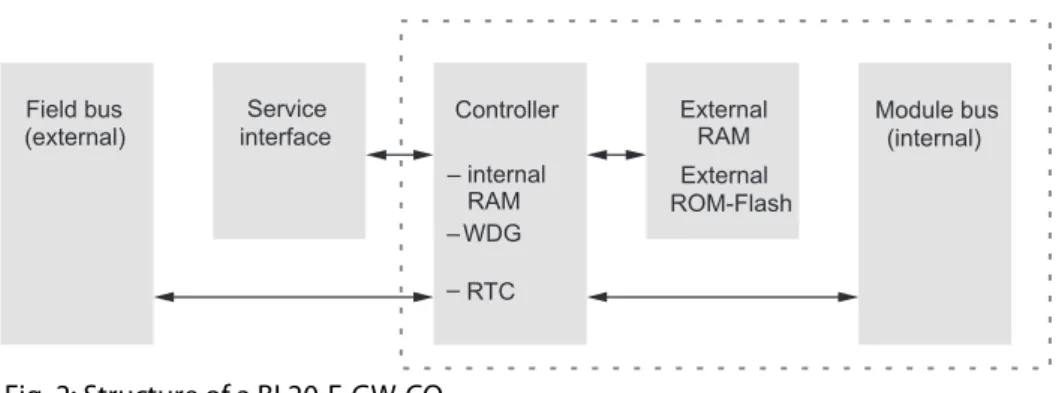
Introduction
Function
Technical data
General technical data of a station
Shock resistance according to IEC shocks, sinusoidal half-wave 15 g peak value/11 ms, counting in ± direction per space coordinate Resistance to repetitive shock according to IEC 68-. This device may cause radio interference in residential and small industrial (residential, business and commercial) areas. In this case, the operator may be expected to take appropriate measures to suppress the interference at his own expense.
Technical data for the push-in tension clamp terminals
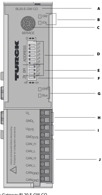
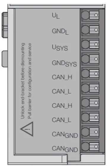
Connection options at the gateway
Power supply
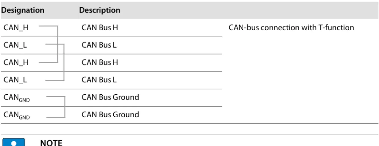
Fieldbus connection via push-in tension clamp terminals
Connection through an I/O-ASSISTANT cable
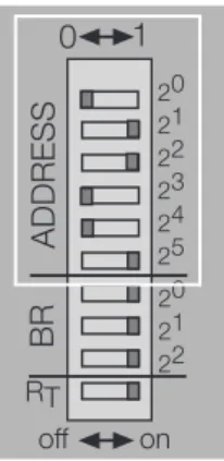
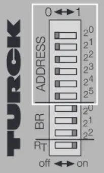
Setting the node ID
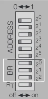
Setting the bit rate
Autobaud function
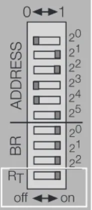
Activation of the terminating resistor
Storing of the BL20 station configuration
Status indicators/diagnostic messages
Diagnostic messages via LEDs
Compare the configured list of modules in your BL20 station with the current configuration. 4 Hz No module bus communication Check the station configuration and the voltage supply at the port and at the supply modules. Check that the fieldbus is terminated with a termination resistor, if the BL20-CANopen port is the last node in the bus topology.
Check the CANopen cable for possible damage and for correct connections – Check that the correct bit rate has been. BUS Green The configured modules correspond to the modules in the station, communication is running. The CANopen description for BL20 can be found in a separate manual "BL×× CANopen object register" D301230 at www.turck.de.
Random module arrangement
Complete planning
Maximum system extension
Power supply
- Power supply to the gateway
- Module bus refreshing
- Creating potential groups
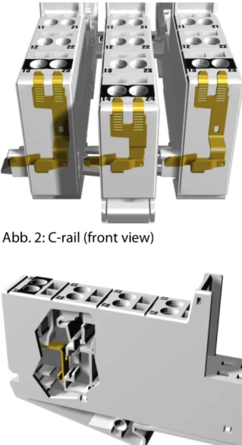
- C-rail (cross connection)
- Direct wiring of relay modules
When using a digital input module for 120/230 V AC, it must be ensured that a potential set is created in connection with the Power Feeding module BL20-PF-120/230VAC-D. The C rail of the base modules for the power distribution modules is mechanically separated; thereby isolating neighboring supply groups. Access to the C rail is possible with the help of basic modules with a C in their designation (for example, BL20-S4T-SBCS).
This makes it clear that the C busbar is separated from the adjacent potential group to its left. The C-rail can be used as required by the application, for example as protective earth (PE). In this case, the PE connection of each power distribution module must be connected to the DIN rail via an additional PE terminal, which is available as an accessory.
To achieve this, the load voltage is connected to a power supply module with the BL20-P4x-SBBC base module. Make sure that after using the C rail for the common voltage supply of relay modules, an additional supply module is used for the potential isolation of the following modules. The corresponding wiring diagram including the jumpers can be found in the BL20 I/O module manuals (German: D300716, English: D300717).
In this case, base modules without C-rail connections should be selected to guarantee possible isolation to adjacent modules.
Protecting the service interface on the gateway
Plugging and pulling electronics modules
Extending an existing station
Firmware download
General notes
- General
- Cable routing
- Lightning protection
- Transmission cable
Outside buildings, cables must be routed in closed (where possible) metal cable ducts. The cable duct joints must be electrically connected and the cable ducts must be earthed. The cables must be routed in double-earthed metal pipes or in reinforced concrete cable ducts.
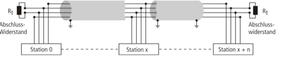
Signal cables must be protected against overvoltage with varistors or surge arresters filled with inert gas. Varistors and surge arresters should be installed at the point where the cables enter the building. The slaves on the bus are connected to each other with fieldbus lines that correspond to DeviceNet specifications (ODVA Spec.
The bus cables must be terminated at the beginning and at the end with a bus termination resistor. Turck offers different types of lead line cables as pre-molded or bulk cables with different connectors. For ordering information on the available cable types, please refer to the BL20 catalog.
When laying cables outside buildings, observe all applicable guidelines for internal and external lightning protection and all grounding regulations.
Potential relationships
General
Potential-free installation
Electromagnetic compatibility (EMC)
- Ensuring electromagnetic compatibility
- Grounding of inactive metal components
- PE connection
- Earth-free operation
- Protection against high frequency interference signals
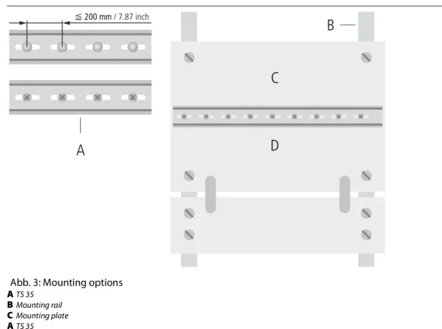
- Mounting rails
- EMC compliant cabinet installation
To comply with the radiation limits according to EN, the power supply cables for the power supply of the gateway must be routed via a ferrite ring (PS416-ZBX-405). All mounting rails must be mounted on the mounting plate with low impedance, over a large area and must be properly grounded. Fasten the mounting rails over a large area and with low impedance to the support system by means of screws or rivets.
Protect the connection point from corrosion (for example with grease; caution: use only suitable grease). Adhesive tapes bond inactive metal components when large surface contact cannot be created. Mounting plates used to hold control components must have a large surface area in contact with the case body. Protective conductive rail.
The protective conductor rail must also be connected over a large area to the mounting plates and additionally with an external cable (diameter at least 10 mm2/0.015 inch2) to the protective conductor system to avoid interference currents.
Shielding of cables
Potential compensation
For compensation cables routed on both sides, the compensation cable impedance must be significantly less than that of the shield connection (max. the compensation cable must be connected to the protective conductor over a large surface and must be protected against corrosion Compensation cables and data cables must be routed as close to each other as possible, which means that the enclosed area must be kept as small as possible.
Switching inductive loads
Protection against Electrostatic Discharge (ESD)