i
CYLINDRICAL DIELECTRIC RESONATOR ARRAY ANTENNA WITH PARABOLIC REFLECTOR
By
MOHAMAD HASAN ISMAIL FINAL PROJECT REPORT
Dissertation submitted in partial fulfillment of the requirements for the
Bachelor of Engineering (Hons) (Electrical & Electronics Engineering)
Universiti Teknologi PETRONAS Bandar Seri Iskandar
31750 Tronoh Perak Darul Ridzuan
© Copyright 2013 by
Mohamad Hasan Bin Ismail, 2013
ii
CERTIFICATION OF APPROVAL
CYLINDRICAL DIELECTRIC RESONATOR ANTENNA WITH PARABOLIC REFLECTOR
by
Mohamad Hasan Bin Ismail
A project dissertation submitted to the Department of Electrical & Electronic Engineering
Universiti Teknologi PETRONAS in partial fulfillment of the requirement for the
BACHELOR OF ENGINEERING (Hons) (ELECTRICAL & ELECTRONIC ENGINEERING)
Approved:
__________________________
(Mohd Azman bin Zakariya) Project Supervisor
UNIVERSITI TEKNOLOGI PETRONAS
TRONOH, PERAK
January 2014
iii
CERTIFICATION OF ORIGINALITY
This is to certify that I am responsible for the work submitted in this project, that the original work is my own except as specified in the references and acknowledgements, and that the original work contained herein have not been undertaken or done by unspecified sources or persons.
______________________________
MOHAMAD HASAN BIN ISMAIL
iv
ABSTRACT
This report highlights the investigation on cylindrical dielectric resonator array antenna, CDRA feed with micro-strip transmission line through aperture coupling with the addition of a parabolic reflector. The application of interest for this design is for WLAN data transmission IEEE 802.11 a band. The CDRA proves to be a viable alternative to the current micro-strip patch antenna as it gives higher gain, wider bandwidth and also low radiation loss. The CDRA antenna with parabolic reflector is design for a point to point WLAN application at a center frequency of 5.52 GHz. The design simulation is done using the Computer Simulation Technology (CST) while the substrate prototype is fabricated using printed circuit board (PCB) with the CDRA glued to the substrate using silicon glue.
This report consists of an introduction, problem statement, objectives, literature review and methodology used to conduct the research on the CDRA design and its performance. This report also discuss the result obtain through CST simulation and the actual prototype radiation pattern and the maximum gain obtained.
v
ACKNOWLEDGEMENTS
First of all, praise to Allah the Almighty for his blessing, guidance and for giving me the strength to embark on this research on dielectric resonator array antenna technology, Alhamdulillah. Special credit goes to my beloved family and friends for their moral support and motivation directly or indirectly.
I would like to express my gratitude to my final year project supervisor, Mr.
Mohd Azman Bin Zakariya for all his guidance and attention towards my research that has hugely contribute to achieving the objectives of this project. His guidance and wisdom has helped me to understand and master this FYP topic. Thanks to the technician, especially Mr. Adz Jambros and Mr. Hasrul who has help me throughout the completion of this FYP project. Not forgetting Mr. Syed Muzammil Bin Syed Ali and Mr. Affan Bin Baba, Graduate Assistant (GA) for their consultation that has help me to solve problems encountered along the project execution.
Last but not lease, I also would like to express my gratitude to all those that involved directly or indirectly that has help me through out this project research.
vi
TABLE OF CONTENTS
ABSTRACT ... iv
ACKNOWLEDGEMENTS ... v
TABLE OF CONTENTS ... vi
LIST OF FIGURES ... viii
LIST OF TABLES ... x
LIST OF ABBREVIATIONS ... x
Chapter 1 ... 1
Introduction ... 1
1.1. Background of study ... 1
1.2 Problem statement ... 3
1.3 Objectives ... 5
1.4 Scope of Study ... 5
1.5 Relevancy and Feasibility of the Project ... 6
Chapter 2 ... 7
Literature review ... 7
2.1 Introduction to antenna technology ... 7
2.2 IEEE standard for wireless communication ... 8
2.3 Dielectric Resonator Antenna overview ... 9
2.4 Properties of dielectric resonator antenna ... 11
2.5 Shape of the dielectric resonator antenna ... 11
2.5.1 Hemispherical dielectric resonator antenna ... 12
2.5.2 Cylindrical dielectric resonator antenna ... 12
2.5.3 Rectangular dielectric resonator antenna ... 13
2.6 Radiation pattern ... 14
2.7 Dielectric Resonator Array antenna ... 15
2.8 Feeding method ... 16
2.9 Coupling Method ... 17
vii
2.10 Reflector ... 18
Chapter 3 ... 19
Research Methodology ... 19
3.1 Method of conducting the project work ... 19
3.2 Design and simulation of CDRA ... 21
3.2.1 CST simulation design step ... 23
3.2.2 S-Parameter and Transient Solver ... 26
3.3 Fabrication of the CDRA with parabolic reflector ... 28
3.3.1 Tools and Equipment used ... 28
3.4 Test measurement of the CDRA antenna ... 30
3.4.1 Agilent Network Analyzer ... 30
3.4.2 Standard Gain Horn Antenna ... 30
3.4.3 Measurement set up for antenna gain set up ... 31
3.5 Gant Chart ... 35
Chapter 4 ... 37
Result and Discussion ... 37
4.1 CST Design of DRA antenna with rectangular slot ... 37
4.2 Simulation design with Reflector ... 41
4.3 Prototype testing without reflector ... 46
4.4 Prototype testing with Parabolic Reflector ... 49
4.5 Comparison between simulation and prototype result ... 53
4.6 Radiation pattern comparison of the CDRA antenna ... 54
Chapter 5 ... 68
Conclusion and Recommendation ... 68
5.1 Conclusion ... 68
5.2 Recommendation ... 69
References ... 71
viii
LIST OF FIGURES
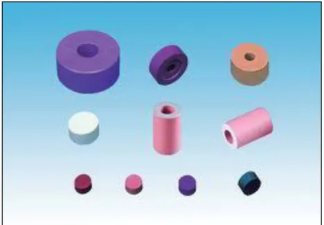
Figure 1.1: Various shape and sizes of the Dielectric Resonator ... 1
Figure 1.2: Typical internet Wi-Fi router ... 3
Figure 2.1: Example of WiFi Router ... 7
Figure 2.2: 802.11 Wireless LAN applications ... 8
Figure 2.3: Example of cylindrical DRA ... 10
Figure 2.4: Hemispherical DRA ... 12
Figure 2.5: Example of cylindrical DRA ... 13
Figure 2.6: Example of Rectangular DRA ... 14
Figure 2.7: Radiation pattern of the DRA ... 15
Figure 2.8: Dielectric resonator array antenna ... 15
Figure 3.1: Project methodology ... 20
Figure 3.2: CST design methodology ... 21
Figure 3.3: CST Microwave Design Studio Suite ... 22
Figure 3.4: Cylindrical Dielectric Resonator Antenna Array (CDRA) ... 22
Figure 3.5: Parabolic reflector ... 29
Figure 3.6: Agilent Network Analyzer ... 30
Figure 3.7: Standard Gain Horn Antenna ... 31
Figure 4.1: Front side of the CDRA antenna design ... 37
Figure 4.2: Back side of the CDRA antenna design ... 38
Figure 4.3: S11 Parameter graph ... 39
Figure 4.4: Left side of the CDRA antenna ... 39
Figure 4.5: Far-field radiation propagation of the antenna at 5.55 GHz ... 40
Figure 4.6: Far-field radiation propagation in polar form ... 40
Figure 4.7: Front side of the CDRA antenna with parabolic reflector ... 41
Figure 4.8: Right side of the CDRA antenna with parabolic reflector ... 42
Figure 4.9: S11 graph of the antenna ... 43
Figure 4.10: S11 graph showing the center frequency of the antenna ... 43
Figure 4.11: The radiation pattern in 3D ... 44
Figure 4.12: Radiation pattern in polar form ... 45
Figure 4.13: Front side of the prototype CDRA ... 46
Figure 4.14: Back side of the prototype for CDRA antenna ... 46
ix
Figure 4.15: S Parameter for CDRA array antenna with rectangular slot ... 47
Figure 4.16: Polar radiation of the CDRA ... 48
Figure 4.17: Left side of the CDRA antenna gain measurement set up ... 49
Figure 4.18: Front side of the gain comparison testing set up done in the lab ... 50
Figure 4.19: Network analyzer measurement showing at 5.5 GHz ... 51
Figure 4.20: Polar radiation of the CDRA array antenna ... 52
Figure 4.21: Simulated CDRA antenna polar radiation graph ... 54
Figure 4.22: Prototype CDRA antenna polar radiation graph ... 55
Figure 4.23: Simulated CDRA antenna with reflector polar radiation graph ... 56
Figure 4.24: Prototype CDRA antenna with reflector polar radiation graph ... 56
Figure 4.25: Comparison of Simulated S11 parameter with prototype ... 57
Figure 4.26: Comparison of return loss (S11) with and without reflector ... 58
Figure 4.27: Simulated return losses (S11) according to different width of the slot .. 59
Figure 4.28: Simulated return losses (S11) according to different length ... 60
Figure 4.29: Simulated Far Field Directivity with and without reflector ... 61
Figure 4.30: Peak directivities for the antenna with and without reflector ... 62
Figure 4.31: Comparison of back lobe level with and without reflector ... 64
Figure 4.32: Effect of size of the reflector on the directivity of the antenna ... 65
Figure 4.33: Effect of the size of the reflector on the back lobe of the antenna ... 66
x
LIST OF TABLES
Table 4.1: Comparison between simulation and prototype result ... 53
Table 4.2: Different slot width versus its resonant frequency ... 59
Table 4.3: Different slot length versus its resonant frequency ... 60
Table 4.4: Directivity of CDRA antenna with and without parabolic reflector ... 63
Table 4.5: Different radius of reflector versus the antenna directivity ... 66
LIST OF ABBREVIATIONS
CDRA Cylindrical Dielectric Resonator Array CST Computer Simulation Technology AUT Antenna under Test
WLAN Wireless Local Area Network
IEEE Institute of Electrical and Electronics Engineers ANSI American National Standards Institute
PCB Printed Circuit Board
1
CHAPTER 1 INTRODUCTION
1.1 Background of study
Antenna is a device that is used in the field of communication in order to transmit or receives information. The basic working principle of antenna is that it sends electromagnetic wave, EM transmissions at a specific frequency where other devices can pick up this transmission, decode it and used the data transmitted. The device that is used for Wireless Local Area Network, or commonly known as Wi-Fi is router. Other device that is able to used Wi-Fi protocol are hand phone, laptops and servers. These devices are able to communicate wirelessly through the usage of a Wi-Fi antenna that radiates the EM wave to transmit and receive information. The advantage of Wi-Fi is that it is low cost as it only needs a router and also a receiver to communicate. This is more cost friendly as compared to wired Local Area Network that uses cables to send information in order for a communication to be established.
Figure 1.1: Various shape and sizes of the Dielectric Resonator
2
Previously, microstrip patch was used to develop antenna because it is inexpensive and also easy to manufacture because of the 2D design. On the other hand, microstrip antenna has low impedance bandwidth; low gain had extra radiations that occur from its feeds and junction. Dielectric resonator antenna offer a significant improvement over the microstrip technology because of the high gain, wide bandwidth and also other property that makes it an interesting area of research for development of antenna.
Dielectric Resonator Antenna is a microwave emitting element that has many shapes depending on the frequency emission it was design to be used. Usually it will be constructed from a block of ceramic material etched onto a metallic radiation board. The antenna is then excited with radio frequency through the center of the DRA using a transmitting circuit. The radio wave which is introduced will be deflected inside the element which is semi permeable to radio frequency and will eventually propagate into open space.
This project will focus on developing a Wireless Local Area Network antenna using dielectric resonator material for the purpose of point to point communication for internet usage. The antenna will be operating at a frequency of 5 GHz band specified by the IEEE 802.11 a band for Wireless communication.
3 1.2 Problem statement
In this modern age, society is becoming more and more connected globally and business and social interaction has rapidly increased due to the advancement in the Internet. The internet nowadays has become a commodity for society with the development and enhancement of communication devices such as smartphone, tablets and personal computer. Therefore, the demand for an improved communication connecting for information transfer has driven innovation to provide such devices for consumers by communication technology companies.
One of the improvements to the communication technology is the introduction of Institute of Electrical and Electronics Engineers, IEEE 802.11 protocol. This protocol is a set of modulation specifications design for implementation of wireless local area network communication at a frequency range of 2.4, 3.6, 5 and 60 GHz bands. The most popular implementation of the IEEE 802 is the IEEE 802.11 b and IEEE 802.11 g which operates at 2.4 GHz. This widely accepted protocol has been used for wireless communication devices such as computer, smartphone and tablets. The downside of the protocol using 2.4 GHz is that it sometimes suffers interference from microwave ovens and Bluetooth devices operating nearby.
Figure 1.2: Typical internet Wi-Fi router
4
A better protocol option is the IEEE 802.11 a band which operates at 5 GHz bandwidth that offers at least 23 channels that are not overlapping to one another.
The protocols allow data transmission at a data rate of 1.5 to 54 Mbit/s. The figure shows a typical internet Wi-Fi router that uses 802.11 b and g protocol. Due to an overwhelming implementation of IEEE 802.11 b and IEEE 802.11 g, 2.4 GHz band, there is an unused 5 GHz band which gives this protocol an advantage over other protocol for device wireless communication. Implementation of such protocol will require an antenna that can operate at 5 GHz band.
Focusing on the Dielectric resonator antenna array, this type of antenna offer a significant improvement over the microstrip, dipole and monopole antenna as it is small, efficient in radiating electromagnetic wave and also cheep to be fabricated. A dielectric resonator antenna is a radio antenna mostly used at microwave frequencies and higher, that consists of a block of ceramic material of various shapes, the dielectric resonator, mounted on a metal surface, a ground plane. Radio waves are introduced into the inside of the resonator material from the transmitter circuit and bounce back and forth between the resonator walls, forming standing waves. The walls of the resonator are partially transparent to radio waves, allowing the radio power to radiate into space.
An advantage of dielectric resonator antennas is they lack metal parts, which become lousy at high frequencies, dissipating energy. So these antennas can have lower losses and be more efficient than metal antennas at high microwave and millimeter wave frequencies. Dielectric waveguide antennas are used in some compact portable wireless devices, and military millimeter-wave radar equipment.
To enhance the performance of the DRA, the array method is proposed. This typical DRA arrays involve number of elements, placed either scattered in a random fashion or in some ordered way. The radiated fields that are propagated from these various arrays are quite different; each has its own distinguishable properties that are ideal for certain uses. The challenge for the implementation of such design is that antenna arrays are systems that need to be improved upon to be able to produce the ideal radiation propagation with a minimized number of points held within a smaller
5
area. There is a requirement to design a compact size of DRA array antenna which is low cost and portable.
1.3 Objectives
The project will focus on the development of cylindrical Dielectric Resonator antenna array. There are two stages of the project which are the design stage through the simulation in the Computer Simulation Technology software, CST and prototype development stage through Printed Circuit Board, PCB fabrication.
The objectives are to:
1. To design the array antenna using dielectric resonators for achieving high gain of more than 10 dBi with directional radiation pattern.
2. To do analysis on design parameters for optimization such as size of element and element spacing.
1.4 Scope of Study
The development of the Cylindrical Dielectric Resonator Antenna array, CDRA array will be using the computer simulation technique where a proposed design will be constructed virtually and the analysis will be done to test the performance of the antenna design prior to the actual fabrication of the prototype.
The CST design suite has been chosen as the software to be used to analyze the electromagnetic wave behavior and the antenna property. The analysis includes the S parameter, the radiation loss property, the operating and center frequency of the antenna radiation. The design need to satisfy the objectives of designing a CDRA antenna which have high gain of up to 10 dBi. The frequency interested is the 5 GHz band specified by IEEE 802.11 a band due to its advantage over other protocols. The design is also includes the usage of a reflector to enhance the maximum gain of the CDRA antenna.
6
The fabrication process follows the simulation design. After the design has been verified to operate at the intended frequency and the gain is high enough for the fabrication to be worthy, the design is send for fabrication. The fabrication stage consists of a few steps where the design is send for substrate fabrication at the PCB lab using a PCB board. Then it is etched with the CDRA and the characteristic of the S parameter is observed and used as a reference for the CDRA positioning on the substrate. The gain is then tested with a Network Analyzer to observe the operation frequency and also the achievable gain without reflector. The final step will be to incorporate the reflector and test for the maximum achievable gain. The fabricated antenna is then package to increase its ecstatic value.
1.5 Relevancy and Feasibility of the Project
The increase demand and usage of a wireless mobile device has created a demand for a wireless communication device that are cost friendly and are portable.
Therefore, it is aimed that this Cylindrical Dielectric Resonator Antenna Array with reflector is able to cope that demand. Within the timeframe of 28 weeks, the progress of project development has been structured so as to be able to achieve the required objective with reference to the key milestone set. With the enormous resources the university have, the objective of this project have been achieved.
7
CHAPTER 2
LITERATURE REVIEW
2.1 Introduction to antenna technology
An antenna is a device function to convert electrical signal into electromagnetic signal and vice versa[1]. The device is used in order to establish a communication channel for transmission and receiving data wirelessly. The antenna must not only be able to transmit and receive information from the Electromagnetic spectrum but also must be able to function for a long distance communication wirelessly[2]. The antenna receives or transmits the electrical signal produce and conducted by an electrical circuit. In order for a communication channel to be establish, the two antenna communicating must be tune in to the same frequency.
Figure 2.1: Example of WiFi Router
With the introduction of wireless mobile devices, wireless antenna technologies have undergone rapid development with devices such as the ipad, smartphone and other wireless mobile devices increasing the demand from the end user for a better performance wireless technology. It has become a race for the telecommunication companies to develop devices that can offer multifunction and
8
performance increase[1]. One of the most interesting developments in the antenna technology is the introduction of a material that is capable of boosting the gain of an antenna electromagnetic wave propagation property that is the dielectric resonator which will be discuss further later in this chapter.
2.2 IEEE standard for wireless communication
Due to the advancement in the area of wireless communication technology, there has been many protocol set for wireless communication. In order for an organized and wide usage of a particular protocol for wireless communication, a standard must be set for the developers to design devices that can establish intercommunication. Therefore, the Institute of Electrical and Electronics Engineers, IEEE has developed a standard that specifies the protocol for wireless communication which is the 802.11 protocol[3,4]. This protocol specifies the basis for wireless network product using wireless fidelity band. The 802.11 introduced by IEEE is a set of media access control (MAC) and physical layer protocol specifically design for implementation of wireless local area network (WLAN) communication.
The standard frequencies specified through the 802.11 implementation are at 2.4, 3, 5, 6 and 60 GHz frequency bands[4].
Figure 2.2: 802.11 Wireless LAN applications
9
The 802.11 standard specifies a series of half duplex over the air modulation technique that uses a common basic protocol. The most popular implementation of the protocol is the 802.11 b and 802.11 g[4]. These protocols use the 2.4 GHz industrial, scientific and medical (ISM) radio frequencies band for communication between devices. Although widely used, the 802.11 b and g has a weakness in the sense that it occasionally suffer interruption from the nearby devices such as microwave ovens, Bluetooth devices and cordless telephones due to the fact that these devices uses the same frequency of operation[5]. The 802.11 a protocol offer a better solution for wireless communication as it uses a 5 GHz frequency band that does not suffer interruption such as those of 802.11 b and g does. This frequency modulation allows transmission and reception of data rate up to 50 Mbps wirelessly[4].
Due to the fact that this frequency protocol are still lack in implementation from main stream devices, the 802.11 a offer an advantage over the 2.4 GHz band protocol. Implementing this protocol have its challenges which are being a high frequency, the EM wave are readily absorb by solid objects thus unable to penetrate walls of building[4,6]. Therefore, it is recommended that the 802.11 a devices be used for a point to point communication in an open space. Because the antenna that will be develop must be able to be used for a point to point communication and does not suffer interference, the 5 GHz 802.11 a band is specified to be used in the design of the antenna. Thus for this protocol implementation, the dielectric resonator antenna will be used.
2.3 Dielectric Resonator Antenna overview
Dielectric resonator antenna, DRA is a resonant antenna that is fabricated from dielectric material of low radiation loss[7]. The resonant frequency of DRA is the function of dimension and its permittivity. Previously, area of research for antenna development was focus on microstrip patch. The Dielectric material later on was discovered to be a good contender to the microstrip antenna because of the unique property it have in propagating signal wave[7]. The dielectric resonator was previously used to develop filter and oscillator as research found the Q-factor of the
10
material to be of significant value. Researches in the area of DRAs have proven that the dielectric material offer an advantage over other antenna types such as[8]:
Figure 2.3: Example of cylindrical DRA
More that 98 percent radiation efficiency due to the lack of conductive element or surface wave losses.
Flexibility of design because many different shape and sizes can be tailor made to suit the Q factor, bandwidth requirement and also its resonant frequency.
Different types of feeding mechanism can be use to excite the DRA material such as probes, slots, microstrip lines, dielectric image guides which makes integration with existing technology easy.
A wide range of permittivity values of the dielectric material can be chosen from 6 to 100 which make the control over bandwidth and size of the DRA flexible.
High efficiency in electromagnetic wave radiation as the DRA has higher error tolerance compare to microstrip patch antenna.
High antenna signal gain over the isotropic antenna waveform.
The resonant frequency and the dielectric constant can be calculated using the formula:
11
√ √ ( ) ( ) (2.1)
√ (2.2) Where = resonant frequency
( )
Due to all this advantages, the dielectric resonator antenna is a good choice in developing an antenna that can achieve a 10 dBi antenna gain objective specified.
2.4 Properties of dielectric resonator antenna
The dielectric resonator antenna is made from a dielectric material usually ceramic that is in powder form. It is press using a mold to form a solid. The structure is the heated to a very high temperature to form a strong block of ceramic[9]. The ceramic then selectively coated with a conductive metallization layer to form a transmission line. The materials used to make such DRA are TiO2, BTS or CCTO ceramic compound[10-12].
2.5 Shape of the dielectric resonator antenna
The dielectric resonator antenna can be made into any shape. Usually the shape chosen is cylindrical, rectangular or hemispherical[8,13]. All of the shapes mention has its own advantage and disadvantage that the designer can choose to form the required design to achieve their objectives which will be discuss in detail in this chapter.
12
2.5.1 Hemispherical dielectric resonator antenna
The hemispherical DRA offer an advantage over cylindrical and rectangular shaped DRA because of its simple design and few variables that is the radius and dielectric constant. The variable is manipulated in to obtain the desired properties such as resonant frequency and Q factor[13]. The disadvantage of a hemispherical DRA is that the designer will not be able to control the resulting bandwidth because of the limitation in manipulated variable in designing such as the dimension. It is also difficult to fabricate as compared to cylindrical and rectangular shape DRA[13,14].
Figure 2.4: Hemispherical DRA
2.5.2 Cylindrical dielectric resonator antenna
The cylindrical dielectric resonator antenna offer the designer a higher degree of flexibility compare to the hemispherical DRA because the added manipulative variable which is the radius and height. The ratio of height over radius can be manipulated to get the required specification such as Q factor, resonant frequency and the bandwidth[13]. The cylindrical DRA is much easier to fabricate than the hemispherical DRA[12]. The modes can also easily excite to create an Omni directional or broadside radiation pattern. The CDRA is said to have a
13
radiation property that is more directional and therefore suitable for the purpose of this project to make a directional point to point antenna.
Figure 2.5: Example of cylindrical DRA
2.5.3 Rectangular dielectric resonator antenna
The rectangular DRA offer a significant flexibility for designer to create a custom specification for the antenna application. The variables that can be change are the height, (d), the width, (a), the length, (b) and the dielectric constant. In an isolated environment, the rectangular DRA can be excited through two modes which are the transverse electrical, TE and transverse magnetic, TM mode[13]. If the DRA is mounted on a ground plane, only the TE mode that can be usually excited. Proper design of the rectangular DRA will result in elimination of unwanted mode appearing on the operating frequency[14]. Because of the degree of freedom to design the antenna, the rectangular DRA can sometimes be too complicated to design in order to get the proper result.
14
Figure 2.6: Example of Rectangular DRA
2.6 Radiation pattern
Radiation pattern of an antenna is the graphical representation of the radiation properties if an antenna as a function of space. The energy emitting from a transmitting antenna travel in all direction that is in 3 dimensions, 3D. A radiation is said to be isotropic if the radiation is emitted in all direction in the same energy intensity[15]. This ideal radiation pattern does not exist in the real world antenna application but it is used as a reference to compare the real world antenna radiation to the ideal radiation. Another term used to describe a particular shape of radiation is the Omni directional which means the antenna radiates isotropic-ally in a single plane, usually the x, y or z plane[8,16]. The third and also the most common radiation pattern is the directional pattern. The directional pattern points maximum amount of radiation to a single part of the planes. This is the direction where almost all of the radiation emitted by the antenna travel. Figure below shows such radiation pattern where the energy intensity is classified into a few categories which are the main lobe, the side lobe and the back lobe.
15
Figure 2.7: Radiation pattern of the DRA
2.7 Dielectric Resonator Array antenna
The dielectric resonator can be arranged in an order to form an array of DRA that result in boost in antenna gain for the purpose of wireless communication. The performance of the DRA array are a function of configurations such as the dimension, the spacing between DRA, the mode of operation and also the feeding mechanism used[17,18]. Among the major feeding method is the slot coupling, microstrip coupling and the probe coupling[18].
Figure 2.8: Dielectric resonator array antenna
16
The E plane radiation pattern are effected by the spacing of the DRA in such a way that for different number of DRA used, n=2, 4 and 8, the spacing is x , and where is the free space wavelength. The degree of directivity increases with the addition of number of DRA used. The spacing is commonly used for design and study of the DRA arrays. The directivity of the DRA in the E plane and the H plane array with is also affected by the number of DRA used. It is observed that the directivity gain increases with the addition of DRA[8,18].
2.8 Feeding method
There are many feeding method that can be used to excite the DRA such as slot aperture, coaxial, dielectric image guide and microstrip line[8,13]. In slot aperture method, the DRA is excited through an opening in the ground plane below where the DRA is placed. Coaxial feed on the other hand is using a probe that is placed besides the DRA or is trust inside the DRA. The amount of coupling is varied by adjusting the position of the probe[8,13,17]. The disadvantage of coaxial probe is that it cannot handle high frequency application. But for the purpose of this project, only the microstrip line feeding method will be future discuss because of its various benefits.
In the microstrip line feeding, a conducting strip made from metallic element is used to excite the DRA. The electric current flowing through the microstrip produces magnetic field that excite the DRA. The microstrip line feeding is easy to fabricate and is simple to be implemented. It also has high impedance matching. The challenges of this method is that the polarization of the array will have to be analyze according to the orientation of the microstrip which means that the magnetic field in the DRA will be parallel to the microstrip line[19].
17
In order to achieve the objective of designing an antenna that can operate at high frequency, the microstrip is chosen as the feeding method because it can be design to withstand high peak power and maintain the impedance of the transmission line[8,18]. Thus, by using the microstrip as the excitation method, the antenna for wireless application that operates at a high frequency can be design with impedance matching and efficient excitation.
2.9 Coupling Method
The selection of the coupling method plays an important role in determining the resulting radiation pattern of the antenna designed. One common method of exciting a DRA is through an opening in the ground plane where the DRA is positioned. Rectangular slot is by far the most common aperture coupling method used based on the literature review[20,21]. The amount of leak radiation from the DRA is minimized by keeping the slot small enough to not allow large leakage to flow through[20]. The aperture is then feed electrical signal by using microstrip line.
The aperture coupling ofer an advantage over other types of coupling as it isolate the radiating aperture from unwanted coupling from the microstrip line.
In order to achieve maximum coupling, the aperture should be located in the region where there is strong magnetic fields for example on top of the microstrip line separated by the ground substrate[21]. This method of coupling is easy to fabricate. It also gives impedance matching higher than that of coaxial line or waveguides. Below are guidelines on how to design aperture slot[8]:
The length of the slot must be large enough for a sufficient coupling between the DRA and the microstrip line but not so large that it does not resonate within the operating frequency. This could cause high unwanted back lobe radiation.
√
(2.3) Where
and are the dielectric constant of the DRA and substrate.
18
The width of the slot is keep minimum to avoid back lobe radiation. The recommended value is
(2.4)
The stub extension s is selected so tat its reactance cancels out that of the slot aperture which is usually chosen to be:
(2.5) Where is the guided wave in the substrate.
2.10 Reflector
Reflector plays a major role in enhancing the potential of the DRA antenna that will be design. The properties of the reflector will serve as to boost the radiation from the DRA and also to deviate and channel the back lobe radiation to the main lobe in front[9]. It will focus the radiation to a focal point where the maximum radiation is located[22]. There are a few basic reflector shapes which are the elliptical, the corner reflector and also the parabolic reflector[8]. The most popular implementation of reflector is the parabolic reflector. This is because of its advantage over other types of reflector such as good cross-polarization in its radiation pattern[9,23]. Therefore, this type of antenna is suitable for point to point antenna implementation. The parabolic reflector also serves to eliminate noises from nearby radiating EM wave because it focuses the receiving or emitting radiation into the receiving circuit.
19
CHAPTER 3
RESEARCH METHODOLOGY
3.1 Method of conducting the project work
This chapter describes the methodology used to conduct the Cylindrical DRA antenna with reflector design and fabrication work for the completion of final year project. The initial works includes refining the problem statement of current implementation of wireless antenna available on the market. The feasibility and relevancy of the project is then explained to readers in order to give explanation on the project execution. The dielectric resonator material is then provided as a solution to the current implementation of wireless antenna under IEEE 802.11 wireless LAN protocol.
To understand the previously developed design, literature review is conducted and from the review paper that are mostly obtained from IEEE site. A summary of review paper is done which act as a foundation for understanding of the working principle and also tools used to develop and analyze the DRA. Through the literature review, past advancement in the project related area which is the dielectric resonator antenna array is obtained. The devices mention in all articles is thoroughly researched and considered for usage on the project. Based on the information obtained, the project title is proposed which is to design a cylindrical dielectric resonator antenna array with reflector and try to achieve a gain of 10 dB.
In any project execution, proper definition of the objective and steps taken in order to achieve the set objectives is crucial. Therefore, a well refine objectives is set to firstly achieve a cylindrical DRA antenna with reflector that is able to achieve a 10 dBi gain. The second objective is set to analyze the design of the CDRA in order to optimize the achievable gain through manipulation of the design variable of the CDRA antenna. The analysis of the design is then documented for research and development purposes in the future.
20
Figure 3.1: Project methodology
21 3.2 Design and simulation of CDRA
In order to design the CDRA antenna with parabolic reflector, specific software is chosen to be used for the simulation of the antenna. It is decided that the design will be using Computer System Tool (CST) Studio Suite. The shape of the design, the dielectric property, its coupling method, and feed voltage will be predetermined in the CST software. The parameters for the design can be determined from reference on previous development by other researcher or through trial and error method. The design is the made in the CST simulation. The transient respond is chosen to evaluate the performance of the antenna. The design is the tested to study its resonant frequency, bandwidth, signal gain, shape of the radiation propagation etc. The S parameter graph is observed.
Figure 3.2: CST design methodology
22
Figure 3.3: CST Microwave Design Studio Suite
The CST Microwave Design software is used to design the antenna. It is also used to analyze the electromagnetic wave propagation from the antenna.
Modification of the design is also done through this software to find configuration that is able to maximize the performance of the antenna.
Figure 3.4: Cylindrical Dielectric Resonator Antenna Array (CDRA)
This special design of the cylindrical DRA is used as the main component of the antenna and function to radiate the standing electromagnetic wave induced by the electrical signal from the micro-strip. The dimension is specified in the simulation to get the desired result.
23
The radiation propagation loss can be observed by evaluating the S parameter curve. A good design will have a symmetrical s parameter curve with a slope below -10 dB. The farfield is also observed to see the 2D, 3D and the polar EM radiation wave. Good designs have singular maximum radiation pointing outward to a particular degree. The design process will be repeated until a satisfactory result is obtained. A few designs will be proposed and tested to compare the performance of each design. The analysis of the result will be used to stipulate the application where the proposed design can be used.
3.2.1 CST simulation design step
After starting the CST Design Environment and chosen to create a new CST microwave studio project, users are requested to select a template that best fits the device that will be created. For this project, we will be using Antenna (on Planar Substrate) template. The template by default will define the units to mm and GHz, define background of the material to be vacuum and select appropriate boundary conditions.
3.2.1.1 Set the working planes properties
Next step is to set the working plane properties to make the drawing planes large enough for the device design. The working plane should always be larger than the maximum extension of the device structure. The setting can be changed in a dialog box by selecting (EDIT > Working Plane Properties) from the main menu. On the dialog box, you will have to define the size of the working plane, the Raster width and also the snap width. This will ensure a reasonable spaced grid.
3.2.1.2 Draw the Substrate Brick
The first construction step will be to define the substrate layer. This is done by creating a brick made of the substrate material. To do this select (OBJECT >
Basic Shape > Brick). Enter the coordinates numerically by pressing the Tab Key that will open a dialog box. For planar substrate, we will have to define 4
24
coordinates that is chosen to be centered at origin. For a 3D shape, the next step will be to define the height of the substrate. To do this, we will have to press Tab Key again. After all the coordinate and dimension have been defined, a dialog box will appear that summarize all the input.
Assign meaningful name to the brick that have been created. After that, we will need to define the type of material being used as the substrate. In the Material dropdown list, select New Material and key in appropriate type of material, the Epsilon and also Mue. You can also change the colour of the material. Click OK and the substrate will be created in the working plane.
d. Model the Ground Plane
Next is the task to model the ground plane of the antenna. For antenna excitation that will be using microstrip, the substrate electrical boundary defined previously are not suitable, therefore, a new substance needed to be model to act as the ground plane. The ground plate will be located at the top, therefore, to access the top of the plane, we can use rotate function to rotate the model by using (VIEW >
Mode > Rotate). Selecting the desired plate by using (Object > Pick > Pick Face, Rectangular), double click the plate desired.
Next, we need to extrude the plate to create depth of the ground. Use the extrude tool and enter the height and material of the ground plate. We will also need to define the material used as the ground plate. To do this, define the substance in the Material dropdown list. In the case of DRA array, we will use copper as the ground which the DRA array will be etched.
3.2.1.3 Model the DRA
Same as when drawing the DRA, select (OBJECT > Basic Shape >
Cylindrical). Enter the coordinates numerically by pressing the Tab Key that will open a dialog box. For Cylindrical antenna DRA, we will have to define the parameter that is radius and height. The position of the DRA can be defined by entering specific coordinate in the 3D plane. The next step will be to define the height of the DRA. To do this, we will have to press Tab Key again. After all the
25
coordinate and dimension have been defined, a dialog box will appear that summarize all the input. Assign meaningful name to the Cylinder that have been created.
After that, we will need to define the type of material being used as the DRA. In the Material dropdown list, select New Material and key in appropriate type of material, the Epsilon and also Mue. You can also change the colour of the material. Click OK and the DRA will be created in the working plane.
3.2.1.4 Model the excitation microstrip
The step is the same as when we want to create the DRA only this time, we will be using rectangular microstrip places at the bottom of the substrate.
3.2.1.5 Drill hole/aperture/gap
The aperture in the DRA array antenna design will be define using the (OBJECTS> Basic Shapes > Cylinder). Enter the outer radius and skipping the inner radius. We can use the working coordinate system (WCS) to help in defining the dimension of the aperture. To do this, select (WCS > Move Local Coordinates,). As previously, we need to define the material of the shape defined. In this case, vacuum. There will be some intersection dialog box for the intersection of the shape.
Make sure the cylinder is vacuum inside.
3.2.1.6 Define the Waveguide Port
We will need to add the excitation port to the antenna.to do this, select (Object > Pick > Pick face) on the end of the microstrip transmission line. After that, open dialog box (Solve > waveguide Ports) to define the port. Choose the mode to be 1, keep the default setting.
26 3.2.1.7 Define the Frequency Range
In this design, we will look at the operation of the antenna at 5 GHz, therefore, open the frequency range dialog box (SOLVE > Frequency) and enter the range from 4 GHz to 6 GHz.
3.2.1.8 Boundary Conditions
The boundary is necessary because only a limited volume of the calculation domain, it is crucial that we define the boundary condition that considers the influence of the outer space. To do this, open (SOLVE > Boundary Conditions). As general rule, the open boundary conditions is advice to be at least 1/8 wavelength apart from the field source.
3.2.1.9 Define Far-field Monitor
The Far-field distribution describes the graphical radiation pattern of the antenna. We will need to set up the far-field. To do this, open (SOLVE > Field Monitors). Choose Far-field/RCS radio button. Set the monitor frequency to be 5GHz.
3.2.2 S-Parameter and Transient Solver
3.2.2.1 Frequency Range Consideration of the Transient Solver
It is advice to set the range to be 20% to 100% of the frequency studied. In this case we have set the frequency range to be 4 GHz to 6 GHz.
3.2.2.2 Transient Solver Settings
Open (SOLVE > Transient Solver) and set the accuracy to -30 dB, click the special button and tick the restart solver after instability abort. Press start to run the Transient solver.
27 3.2.2.3 Transient Solver Result
We can now analyze the result from the Transient solver. The primary result that we will be concern on is the S dB parameter. Click the |S| dB folder. A graph showing the Magnitude in dB versus the frequency will appear. To find out the maximum efficient frequency of operation, we look at the part of graph that have the minimum dB. This is the resonance frequency.
The second parameter that we will be concern with is the Far-field Monitors.
Click the Far-field folder and it will give you a 3D graph of the antenna radiation propagation. From this, we can analyze the point at which maximum antenna propagation. We can also view the Gain by adjusting the property of the graph and change it to display the main lobe magnitude that is the Gain of the antenna.
28
3.3 Fabrication of the CDRA with parabolic reflector
Based on the designs obtained from the CST, a fabrication process is conducted to test the prototype and confirm the analysis data obtained from the software. The fabrication process follows the simulation design. After the design has been verified to operate at the intended frequency and the gain is high enough for the fabrication to be worthy, the design is send for fabrication.
3.3.1 Tools and Equipment used
In order to achieve the specified objectives, proper tools are required for conducting the project works. This includes the type of software used for the simulation and analysis, the tools used for fabrication and its performance testing.
The fabrication stage consists of a few steps where the design is send for substrate fabrication at the PCB lab using a PCB board. Then it is etched with the CDRA and the characteristic of the S parameter is observed and used as a reference for the CDRA positioning on the substrate. Below are the tools used through-out the extended period of project schedules.
3.3.1.1 Solder lead
The soldering lead is used in order to connect the antenna substrate with the Sub Miniature version, ASMA bulkhead
3.3.1.2 FR-4 Printed Circuit Board
The FR-4 board is use to fabricate the CDRA antenna design because it it easy to fabricate and low cost. The dimension of the FR-4 is set from the design acquire from the simulation result.
29 3.3.1.3 Microstrip
Microstrip lines is used on the antenna design to feed the CDRA. The size of the microstrip is vary depend on the requirement and the fabrication of the microstrip is done using printed circuit board (PCB) technology.
3.3.1.4 Reflector
Reflector is the component used to as catalyst to increase the gain of the signal.
The reflector will be design using aluminum to desired dimension based on the simulation design to reflect the signal from the CDRA. The parabolic reflector is used because of it is the most efficient in focusing the radiation to a single point.
Figure 3.5: Parabolic reflector
3.3.1.5 SMA Bulkhead Connector
Bulkhead connector used as to interface to feed the microstrip line with voltage to stimulate the CDRA to radiate signal.
30 3.4 Test measurement of the CDRA antenna
The gain is then tested with a Network Analyzer to observe the operation frequency and also the achievable gain without reflector. The final step will be to incorporate the reflector and test for the maximum achievable gain. Further analysis will be conducted to verify the designs as a viable alternative to the current implementation of DRA array and the result will later be publish for accreditation by respective university final year project evaluation committee. The fabricated antenna is then package to increase its ecstatic value.
3.4.1 Agilent Network Analyzer
Network analyzer is used to measure the signal transmitted by the fabricate antenna. Network analyzer served to test the result on the frequency, bandwidth and gain of the transmitted signal by antenna.
Figure 3.6: Agilent Network Analyzer
3.4.2 Standard Gain Horn Antenna
Standard gain horn antenna is used to measure the gain of signal transmitted by the fabricate antenna, S21 parameter. Standard gain horn antenna served to measure the result on the gain of the transmitted signal by transmitting antenna. The gain of the antenna used is 10dBi
31
Figure 3.7: Standard Gain Horn Antenna
3.4.3 Measurement set up for antenna gain set up
In order to test the prototype of the Circular Dielectric resonator array antenna, CDRA, a standard procedure set has been followed. This is to ensure the result obtained is accurate and satisfied the standard of measurement for antenna gain. Antenna gain is defined as the ratio of the intensity of an antenna under test relative to an isotropic antenna where the radiation pattern is evenly propagated in all direction. The unit used to define such gain is specified to be “dBi” where dB refers to the ratio and “I” signifies the relative comparison to an isotropic antenna.
The gain-transfer or also known as the gain-comparison method is the most commonly used method of measuring the power gain of an antenna according to IEEE standard Test Procedures For Antenna, ANSI/IEEE std 149-1979.
The gain transfer method requires 3 antennas – 1 antenna under test, AUT, and 1 “don’t care”. The AUT is the antenna that is need to measure to find the gain.
The reference antenna is the one that the gain is known (Gref) in this case, the omnidirectional antenna of 5 dB gain. It is used as a benchmark. The “don’t care”
antenna which in this test is a 10 dBi gain horn antenna is basically the antenna that the gain is not required to be known but must have at least sufficient dynamic range to enable it to transmit radio frequency reaching the AUT. The test requires the usage of network analyzer to monitor and measures frequency pattern of the antenna
32
AUT. The network analyzer is used because it have both transmitter and receiver port.
3.4.1.1 Procedures:
1. The “don’t care” X horn antenna and the reference, omnidirectional antenna is mounted on a holder each.
2. The far-field separation, R, is set between the two antennas.
3. The “don’t care” X antenna is connected to port 1 (transmitter) of the network analyzer and the reference antenna is connected to port 2 (receiver) side of the network analyzer.
4. The antenna is aligned to get the maximum polarization and direction of maximum radiation intensity.
5. The S21 measurement function is activated on the network analyzer.
6. The response/normalize calibration is performed which should produce a flat S21
response at 0 dB across the selected frequency range. This means that the gain is now normalized to the reference antenna.
33
Figure 3.8: Setup for normalization to a reference antenna
7. The reference, omnidirectional antenna is replaced with the AUT at the exact position and alignment.
8. The new S21 value is recorded. This is the gain of the AUT relative to the omnidirectional antenna.
9. To get the total gain of the AUT, the gain recorded must be add with 5 dB gain of the omnidirectional antenna.
It has been specified by the Institute of Electrical and Electronics Engineer, IEEE method to measure the gain of a particular antenna under test for the farfield measurement. The instruction has been followed to get an accurate measurement of the CDRA antenna. The formula for calculating the separation distance between the antennas under test with the reference antenna is given as:
34
(3.1)
Where
= separation distance between the antenna
= the largest Dimension of the antenna under test λ = the wavelength of a 5.5 GHz antenna frequency
While the wavelength is obtain from the formula:
(3.2) Where
λ = the wavelength of a 5.5 GHz antenna frequency c = the speed of light, 3 x 10^8
f = frequency of the antenna under test, 5.52 GHz
The calculated wavelength is about 54 mm while the largest dimension of the antenna which is in this case the parabolic reflector for the CDRA with parabolic reflector, while the largest dimension for the CDRA without reflector is the substrate which is at 50mm. The separation distance for the CDRA with parabolic reflector is measured to be 3 meter while for the CDRA without reflector, the distance is 92 mm.
There is a significant increase in the separation distance between the antenna under test for CDRA with and without parabolic reflector due to the larger dimension of the parabolic reflector. This makes the separation distance to be further for farfield gain measurement for the prototype.
35 3.5 Gant Chart
12345678910111213141234567891011121314 Title Proposal Literature Review/ Data Collection Antenna Designing and Simulation Fabrication Testing Documentation key milestone indicator
Activities
Semester 1Semester 2 Week NoWeek No
36
The Gant chart above shows the execution of project work that has begun since week 1 of the first semester which is in the May of 2013. The purple box is the key milestone indicator which is the due date of the initial and final step of each activities. The project is estimated to complete within 28 weeks which is a 2 semester course. The project is works include defining the problem and objectives of the final year project. It also includes the literature review of previous and current implementation of the antenna technology, its protocol and devices that is use to transmit electromagnetic wave for 802.11 Wireless LAN technology. There are 2 main stages for this final year project which is the simulation design of the Cylindrical DRA antenna with parabolic reflector and the fabrication on a PCB board of the actual antenna.
37
CHAPTER 4
RESULT AND DISCUSSION
4.1 CST Design of DRA antenna with rectangular slot
The project is using a 2 element array design with a rectangular slot. The antenna structure is shown in the figure 7 below. The design used FR-4 as a material for the substrate with a epsilon of 4.9 and mue of 1. The dimension of the substrate has been specified to be 40 mm x 50 mm x 1.6 mm. The front side of the substrate will be occupied with the ground, rectangular slot aperture and the DRA array. The back side will be used for excitation of the CDRA antenna using microstrip line.
Figure 4.1: Front side of the CDRA antenna design
40 mm
50 mm 5.5 mm
3 mm
15 mm
3 mm
5.5 mm 15 mm
38
Figure 4.2: Back side of the CDRA antenna design
The Figure 4.2 and 4.2 above shows the concept of the CDRA array antenna with rectangular slot which is design using CST software. The dimension of the design is is 50 mm by 40 mm by 2 mm. The slot is 3mm by 15mm and the CDRA is 5.5 mm radius with the height of 3 mm. The microstrip located at the back of the antenna is 3mm by 42 mm crossing the center axis of the antenna.
The microstrip located at the back of the substrate is configured to have a dimension of 43 mm x 3 mm x 0.05 mm. The material used is copper because it has low resistance therefore conducting the electric signal used for the excitation of the CDRA array antenna. The microstrip is position on one side at the edge of the substrate for connecting with the network analyzer for testing in the prototype.
The CDRA array that is used in this design is positioned at the front side on top of the ground. The dimension will be specified to be radius 5.6 mm, height of 3 mm and the gap between the DRA is set to be 22.45 mm. it will generally be placed on top of the slot for coupling purposes. The material used is CCTO (CaCu3Ti4O12) which has a dielectric constant or epsilon of 55. The slot will be dimension to be 15 mm x 3 mm x 0.05 mm and the gap specified to be 20 mm apart. The coupling method is chosen because it prevent radiation aperture from any unwanted radiation
42 mm 3 mm
39
from the microstrip feed line. The positioning of the slot to be at the center of the CDRA is to enhance the coupling effect. It is proposed to be design on a PCB board and will be sent to the PCB Lab for fabrication after the result of the simulation satisfies the purpose of the project which is to get an antenna that can be used for WIFI at 5.5 GHz for 802.11 a/b/g protocol.
Figure 4.3: S11 Parameter graph
Figure 4.3 above shows the simulation result for S 11 parameter stimulated from 5 to 6 GHz. It is observed that the graph fall below -10 dB at 5.5191 and rises at 5.6044. The bandwidth of the graph is calculated to be 0.0853 GHz. The minimum value from the graph is estimated to be at around 5.559 GHz though not measured in the figure above.
Figure 4.4: Left side of the CDRA antenna
40
Figure 4.5: Far-field radiation propagation of the antenna at 5.55 GHz
Figure 4.4 and 4.5 shows that the antenna propagates in the positive x, negative y and positive z direction. It measures the highest gain obtain to be 7.686 dBi. Therefore, to achieve the highest gain, the receiving antenna should be position in the direction of the red color in figure 4.5.
Figure 4.6: Far-field radiation propagation in polar form
Figure 4.6 shows far-field graph of the antenna radiation in polar form for 5.55 GHz frequency with main lobe magnitude measured to be 7.7 dBi. The main lobe radiation direction is measured to be 0 degree and angular width (3 dB) of 141.2 degree.
41 4.2 Simulation design with Reflector
In order to enhance and focus the radiation from the antenna into a directional antenna pattern, all the scattered standing wave is projected onto a single point of focus. This is done through the usage of a parabolic reflector. The advantage of using parabolic reflector over other types of reflector such as active corner and elliptical reflector is that it has a large front over back dimension ratio which focuses the radiation forward. It is also the most efficient type of antenna and is suitable for usage in a noisy scattering radiation disturbance area according to research.
The parabolic reflector is design within the computer simulation technology, CST suite using a perfect electrical conductor to simulate an idea conductor to reflect all the electromagnetic wave radiated by the CDRA array. The reflector works to reflect the back radiation emanate from the back side of the antenna through the micro-strip and also aperture. This technique increases the efficiency of projecting the radiation onto a single point of focus.
Figure 4.7: Front side of the CDRA antenna with parabolic reflector
140mm
2 mm
42
Figure 4.8: Right side of the CDRA antenna with parabolic reflector
The Figure 4.7 and 4.8 shows the design of the reflector that has been put at the back side of the CDRA array. The separation between the antenna and the reflector has been simulated to provide maximum gain achievable through the reflector design. The size of the reflector has been chosen to provide maximum reflection property around the back of the antenna while still be small enough that an average user can carry and is applicable in real world usage. The separation between the antenna and the reflector is 85 mm while the radius of the reflector is 140mm.
85 mm
43
Figure 4.9: S11 graph of the antenna
The Figure 4.9 above shows the operating frequency of the antenna designed in the CST which is focus for the 5 GHz band. The figure shows the operating frequency at 5.48 GHz till 5.5654 GHz. The bandwidth is calculated to be 0.085366 GHz. The curve of the S11 above shows the lowest return loss of up to -34.391 dBi.
This result has been used as a reference to design the actual prototype for real world usage. It also shows that the operating frequency of the CDRA array is not shifted or distorted by the reflector used as a gain booster for this design.
Figure 4.10: S11 graph showing the center frequency of the antenna operation at 5.52 GHz
44
The Figure 4.10 above shows the S11 graph simulated by the CST software showing a center frequency of 5.52 GHz which is in the area specified in the IEEE 802.11 a wireless LAN protocol. The advantage of using a 5 GHz is that the transfer rate of the antenna will be up to 50 Mbps according to the IEEE protocol. The operating frequency has not been fully utilized with respect to the amount of device design to communicate wirelessly through this frequency. Therefore the are unused bandwidth that can be used for wireless communication for the public to utilize by using the antenna designed. The almost perfect distribution of operation frequency centered at 5.52 GHz means that the radiation loss is almost symmetrical with respect to the center frequency.
Figure 4.11: The radiation pattern in 3D
The Figure 4.11 above shows the 3D standing wave radiation propagation of the CDRA array antenna with the reflector attached to it. It is clear that almost all the back radiation emitting from the back side of the antenna is reflected to the front side and thus focuses the radiation and increase the maximum achievable gain for the point to point communication. The reflector is design to fully reflect the radiation give out by the antenna. A singular maximum radiation point in the figure denote by the red color wave radiation is calculated to be 8.892 dBi. This gain is significantly much larger that the gain obtained from using the CDRA array antenna only which is about 7.7 dBi, an increase of 1.192 dB. This shows that the reflector used function as intended to maximize the achievable gain of the antenna without increasing the number of CDRA used and altering the dimension of the CDRA array antenna.
45
Figure 4.12: Radiation pattern in polar form
The Figure 4.12 above shows the radiation propagation pattern in polar form for a frequency of 5.52 GHz with main lobe magnitude of 8.9 dBi. The main lobe direction at 40 degree and the angular width (3 dB) of 28.2 degree while the side lobe level of -6.6 dB. The shape of the radiation is almost symmetrical with a center angle of 40 degree. By observation, we can see that there is another point where the radiation gain is much larger, as large as 10 dBi at the interval of 0 and 30 degree.
Therefore it can be said that this design in accordance to the objective of getting a 10 dBi gain antenna through the usage of the parabolic reflector that helps boost the gain.
46 4.3 Prototype testing without reflector
The final part of the project is to test the working CDRA array antenna to prove that it can operate at the designed frequency. The prototypes were therefore, fabricated and later were etched with CDRA. It was then tested using network analyzer to obtain the operating frequency and the S parameter which shows the return loss of the emitted frequency. The Network analyzer was set to show a spectrum of frequency from 5 GHz to 6 GHz. Calibration and set up was done prior to the testing of the antenna.
Figure 4.13: Front side of the prototype CDRA
Figure 4.14: Back side of the prototype for CDRA antenna