General Introduction
Importance of the Study
Problem Statement
- Lack of Customizable Rehabilitation Modes
- Lack of Recovery Progress Measurement
- Costly and Heavy
- Lack of Protection Against Unintended Motions
With physiotherapy sessions in Malaysia costing around RM 150 to RM 250 per session, RM 3000 allows the patient to attend at least twelve sessions of physiotherapy. Excessive flexion or extension of finger and wrist joints beyond their static limits would injure the patient and cause pain.
Aim and Objectives
Design and construct a transmission mechanism that drives motion that respects the hand's static constraints and does not exceed the maximum angular velocities that the hand can naturally generate. Design and construct a user interface that allows the patient to select between 3 levels of angular velocity generated by the transmission mechanism and allows the patient to view their recovery progress.
Scope and Limitation of the Study
Design and build a sensor system that can measure the maximum flexion angle at the MCP joint and the maximum extension angle at the wrist joint for measuring recovery progress. Design and build a hand exoskeleton rehabilitation system costing less than RM1500 with attached hand sections weighing less than 500g.
Contribution of the Study
Furthermore, this study will integrate the theory of origami threads into the design of the transmission mechanism for the hand rehabilitation system.
Outline of the Report
Introduction
Stroke and its Prevalence
Post-stroke Effects
Spasticity
66% of patients suffering from spasticity affect their wrist and finger flexor muscles (Kuo and Hu, 2018). When spasticity occurs in the flexor muscles in the wrist and fingers, it will cause a decrease in range of motion in the finger and wrist joints and cause pain in the patient.
Treatment for Spasticity
This injury will limit the patient from performing their daily activities such as grasping objects and squeezing.
Anatomy of the Hand
The palm contains five metacarpal bones while the wrist contains eight bones: scaphoid, triquetrum, lunate, capitate, trapezium, hamate, trapezium and pisiform. Furthermore, the wrist has four joints: ulnocarpal, distal radioulnar, radiocarpal and scaphotrapeziotrapezoid joints (American Society for Surgery of the Hand, 2022).
Kinematics and Kinetics of the Hand
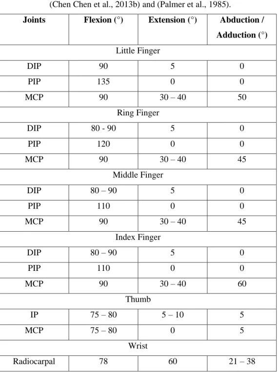
Referring to the results obtained by Chen et al. 2011), the maximum torque of the finger joints of healthy subjects during flexion and extension can be seen in Table 2.2. Referring to the results obtained by Xia and Frey-Law (2015), the maximum angular velocities and maximum torque of the wrist joint of healthy subjects can be seen in Table 2.3 and Table 2.4, respectively.

Hand Functional Requirements for Activities of Daily Living Activities of Daily Living (ADLs) are the everyday tasks that are
Internet of Things Architecture
This layer works to transfer the data sent by the components from the detection layer to the support layer for processing and storage. This layer is used to process, analyze, store and retrieve data sent from the network layer.
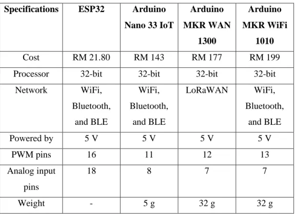
Market Research
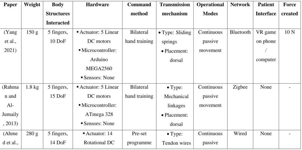
This layer provides human interaction with the system and also executes orders provided by the support layer. Furthermore, methods used to dictate the movements of the exoskeletons include: bilateral hand training (where the exoskeleton copies the movement of the healthy hand), preset program (common for those using CPM), grasp intention detection (common for those using active-assisted movement mode) and button intention detection (where the patient uses their healthy hand to press a button when they want to press a button).
Design Considerations
- Safety
- Static Constraints
- Dynamic Constraints
- Mobility
- Comfort
- Effective Force of Transmission
- Cost
- User-Friendliness
- Weight
- Adjustment to Different Hand Sizes
We should also ensure that the static and dynamic constraints of the hand are respected to ensure that the movement generated by the exoskeleton feels natural (Sarac, Solazzi, & Frisoli, 2019). The weight of the exoskeleton worn on the hand and arm must be light (within 500 g) to ensure that it is portable without causing arm fatigue to the patient (Ates, Haarman, & Stienen, 2017).
Exoskeleton System Design
- Transmission System
- Control System .1 Operational Modes
- Microcontrollers
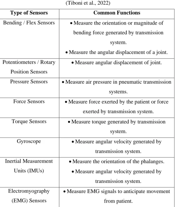
- Sensors
- Wireless Networks
- User Interface
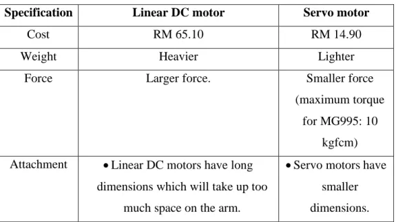
Referring to Table 2.7, the servo motor is chosen because it is cheaper, lighter and would not take up much space. Referring to the comparisons made in Table 2.10, the Android mobile application was chosen as the type of user interface.
Origami String as Transmission Mechanism
This would be a useful design in the exoskeleton to limit angular displacement of the transmission system within the static constraints of the finger and wrist joints. On the other hand, the progress of the patient's recovery can be evaluated by detecting the active range of motion that can be performed by the patient himself.

There are many methods for assessing motor recovery, such as: modified Ashworth scale, Fugl-Meyer score (upper extremity) and active range of motion. Since this range of motion can be sensed by flex sensors, it can be performed with a hand exoskeleton. In these classes, patients were thinking about how to fold a series of origami models that are very complex.
Summary of Findings
Patients who participated in these sessions showed a greater improvement in subtest scores for the Jebsen-Taylor Hand Function Test compared to the control group. The subjects were instructed to fold origami cranes for 40 to 50 minutes a day for a period of 4 weeks. Those who participated in these folding sessions showed a significant improvement in the Purdue Pegboard Test and the Grooved Pegboard Test compared to the control group.
Introduction
Specifications of Exoskeleton System
The maximum angles generated by the transmission mechanism at PIP, MCP and radiocarpal joints must respect the static constraints of the hand. In addition, the maximum angular velocities generated by the transmission mechanism must not exceed the maximum angular velocities naturally generated by the hand. The user interface allows patients to select from 3 levels of angular velocity generated by the transmission mechanism.
Work Plan
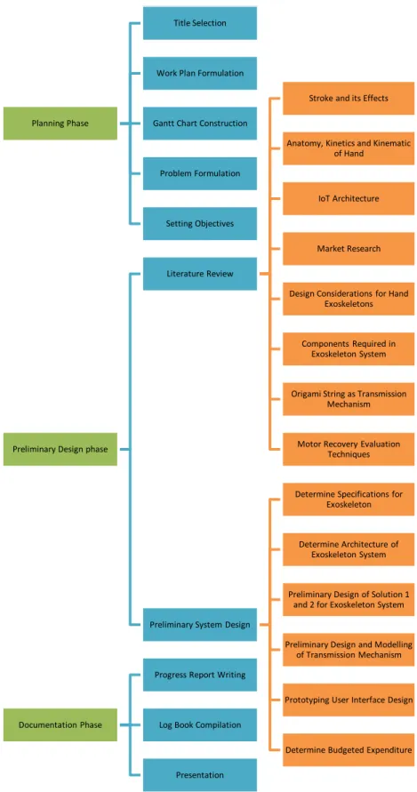
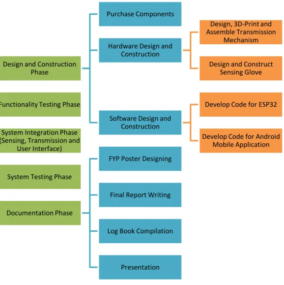
Work Breakdown Structure
Gantt Chart
Architecture of Hand Rehabilitation Exoskeleton System Figure 3.5 illustrates the architecture design for the exoskeleton system
Anatomical Dimension Assumptions
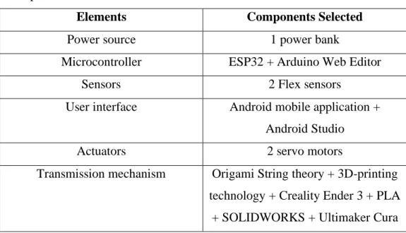
Components Chosen for Each Element in the System Architecture
- Power Source
- Microcontroller
- Sensors
- Actuators
- Transmission Mechanism .1 Mechanism Design Theory
- User Interface
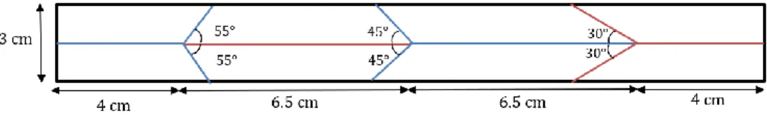
The chosen transmission mechanism design is inspired by the Miura vertex and the origami string concept. The folding patterns shown in Figures 3.6 and 3.8 are subject to change as newer versions of the transmission mechanism are designed. SOLIDWORKS 2019 will be used to design all sections of the transmission mechanism that will be 3D printed.
Performance Testing and Results Analysis Methodology .1 Transmission System
- Purpose
- Steps
- Sensing System .1 Purpose
- Steps
- User Interface .1 Purpose
- Steps
- Total Cost of Rehabilitation System .1 Purpose
- Steps
- Total Weight of Transmission Mechanism Attached to Hand .1 Purpose
- Steps
Place markers (ie, black stickers) on the PIP, MCP, and radiocarpal joints of the index finger. Position the hand so that the sagittal image of the hand is captured by the camera. To assess whether the total weight of the transmission mechanism attached to the hand is less than 500 g.

Total Expenditure
To assess whether the total cost of the entire rehabilitation system is less than RM 1500. Weigh the segments of the transmission mechanism on an electronic scale that has an accuracy of 0.1 g. inch) MG995 Servo.
Summary
Finally, using tools such as Kinovea, Microsoft Excel and an electronic weighing scale, the rehabilitation performance was tested and analyzed for the following areas: transmission system, sensor system, user interface, total cost of rehabilitation system and total weight of the transmission mechanism sections attached to the hand.
Introduction
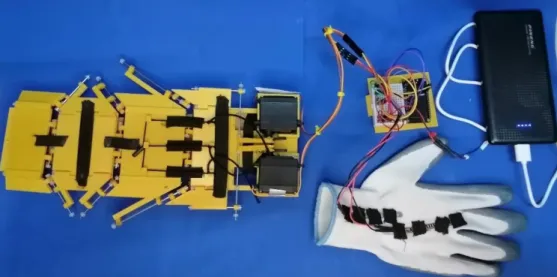
Electrical Circuit
Transmission System
- Origami Theory
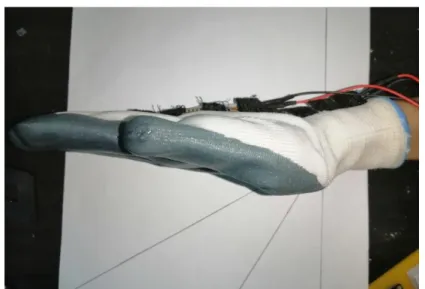
- Final Hardware Design
- Design Features
- Code Design for Android Mobile Application Programme
- Code Design for ESP32 Programme
Initially, the loops designed to connect the segments diagonally, as shown in Figure 4-9(a), have an axis of rotation located at the center of the segment. In addition, the transmission mechanism has protection plates designed as shown in Figure 4-10 to ensure that the segments do not bend in the direction that is not intended. In addition, the first designs had the segments lying completely flat, as shown in Figure 4.11(a).
Sensing System
- Voltage Divider Circuit
- Code Design for Android Mobile Application Programme
- Code Design for ESP32 Programme
- Calibration of Flex Sensors
The complete code annotated with comments can be found in Appendix B, F and G. The purpose of this code is to detect the digital input voltages provided by the flexion sensors, process them into MCP flexion angles and radiocarpal extension angles, detect the maximum angles and then send this data back to the Android mobile application. The hand was held at the position shown in Figure 4.16 to detect the resistance calculated by the ESP32 program when MCP joint was flexed at 90°. Step iii was modified to obtain the different angles, whereby the hand was held at the position shown in Figure 4.18 (a) to measure angles for 60° radiocarpal joint extension and held at the position shown in Figure 4.18 (b) to measure angles for 0° MCP joint flexion and radiocarpal joint extension.
System Integration
Code Design for Android Mobile Application Programme
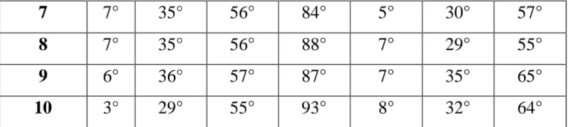
Steps iii to vi were repeated to obtain 10 sets of values and which were tabulated. The mean of these 10 sets of values was obtained and the values of the variables in the ESP32 program were changed accordingly. The complete code for the "HomeDirectory" activity, annotated with comments, can be found in Appendix K.
Code Design for ESP32 Programme
Summary
Introduction
Transmission System .1 Angles Generated
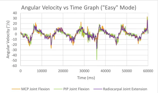
Angular Velocities Generated
From Table 5.2, the maximum magnitude for angular velocities generated at the PIP joints was less than 858°/s for all rehabilitation modes. Furthermore, the maximum magnitude for angular velocities generated at the MCP joints was less than 694°/s for all rehabilitation modes. Finally, the maximum magnitude for angular velocities generated at the Radiocarpal joints was less than 180°/s for all rehabilitation modes.
Sensing System
In addition, the sample values for the maximum angles detected for MCP joint flexion of 60° and 90° and the sample values for the maximum angles detected for 0° radiocarpal joint extension show a symmetrical distribution. In addition, the sample values for the maximum angles detected for 30° and 60° radiocarpal joint extension are slightly positively skewed, while the sample values for the maximum angles detected for 0° and 30° MCP joint flexion are negatively skewed. In addition, the dispersion of the sample values for the maximum angles detected for MCP joint flexion of 30° and 90° and for the maximum angles detected for radiocarpal joint extension of 30° and 60° is greater compared to the other samples.
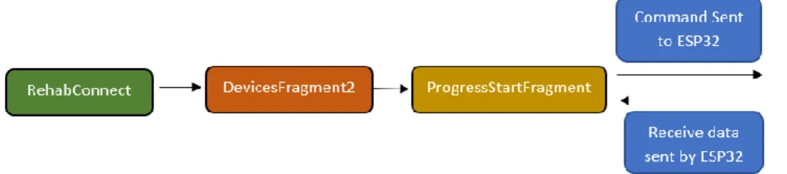
User Interface .1 Activity Flow
Recovery Progress Measurement Activity
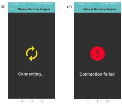
When users select the button shown in Figure 5.12 (a), users will navigate to the page shown in Figure 5.12 (b). The application will loop between the states shown in Figure 5.12 (d) and Figure 5.12 (e) until the ESP32 is powered on. When the ESP32 is powered on, the application will connect to it and navigate to the page shown in Figure 5.13 (a).
Origami Tutorials Activity
Therefore, this study succeeded in designing and constructing a fully functional user interface that can connect to the ESP32 via Bluetooth, allow users to choose between different activities, allow users to choose between different rehabilitation modes, allow users to see their recovery progress, as well as watch tutorial videos on how to fold origami.
Total Cost of Rehabilitation System
Total Weight of Transmission Mechanism Attached to Hand The total weight of the transmission mechanism segments that are attached to
Summary
Other than that, this study succeeded in designing and building a fully functional user interface that can connect to the ESP32 via Bluetooth, allow users to choose between different activities, allow users to choose between different rehabilitation modes, allow users to see their recovery progress, as well as watch tutorial videos on how to fold origami. Next, this study succeeded in building the entire rehabilitation system for RM 533.70, which is less than RM 1500.
Conclusions
Recommendations for future work