The purpose of this research is to manufacture Stewart platform using pneumatic artificial muscles, to analyze the range of motion of the foot/ankle, and to comparative study of the experiment and theoretical data. Ankle joint is one of the important joints in the human body as it helps to maintain body balance during ambulation. Currently Stewart Platform with Shape Memory Alloy (SMA) as actuator is used to measure the range of motion of the foot/ankle involving dorsiflexion, plantar flexion, inversion and eversion.
Power and range of motion output parameters are selected to examine the performance of the Stewart platform. The main contribution of this study is to increase foot/ankle range of motion for stroke patients and athletes who have injured their foot/ankle.
![Figure 1.1: (a) Stewart Platform (b) Ankle Rehabilitation Robots [1]](https://thumb-ap.123doks.com/thumbv2/azpdforg/10231234.0/15.893.229.728.509.773/figure-stewart-platform-b-ankle-rehabilitation-robots.webp)
Shape Memory Alloy (SMA)
Pneumatic Artificial Muscle (PAM)
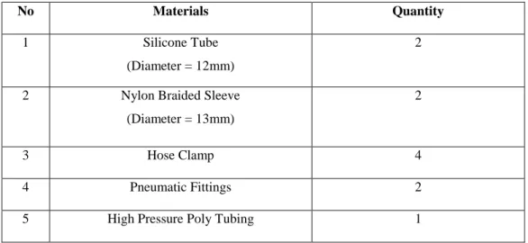
A thin membrane with a property of light weight is one of the important elements of PAM that helps during the replacement of a defective muscle. Another advantage of PAM in their original feature is when power is applied to the PAM, it gives in without any changes of power in the drive [9]. The following Table 2.1 shows the types of braided sleeve materials used as sleeves in Pneumatic Artificial Muscles and their specifications.
![Figure 2.4: Foot and Ankle Orthotics Using Pneumatic Artificial Muscle [11]](https://thumb-ap.123doks.com/thumbv2/azpdforg/10231234.0/21.893.301.710.310.606/figure-foot-ankle-orthotics-using-pneumatic-artificial-muscle.webp)
Hydraulic Actuator
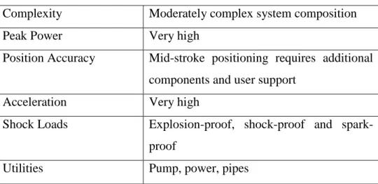
Hydraulic actuator has moderately complex system composition when it comes to the complexity of the actuator. The peak power of the actuator is very high compared to other actuators such as pneumatic and electric actuators. Positional accuracy also known as relative accuracy and absolute accuracy, where for hydraulic actuator additional components and user support are required for mid-stroke positioning.
Low Complexity Devices
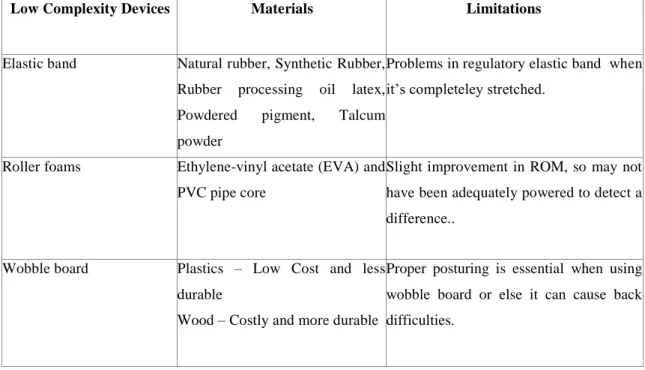
For research and development purposes, numerous devices have been created based on the transfer of the more effective system design that can be used for ankle rehabilitation. Many improvements in ROM can be identified in the complexity of the devices and effectiveness for rehabilitation device development. Good posture is essential when using a wobble board, otherwise it can cause back problems.
These three types of low-complexity devices shown in Figure 2.7, which are widely used in hospitals and therapy centers for foot/ankle rehabilitation, as they are cheap and easy to use. It is made from a mixture of natural rubber, synthetic rubber, rubber processing oil latex, powder pigment and talc. The limitation of elastic rubber bands is that patients find it difficult to control the rubber band when it is fully stretched, which also gave high chances of further injury of the foot/ankle.
A limitation of using the devices is that it will not have enough power to detect a significant difference as it has small improvements in range of motion.
Intermediate Complexity Devices
High Complexity Devices
The Reactive Eccentric mode for submaximal neuromuscular re-education in the early phases of rehabilitation. It has unique control properties that allow for early intervention in all patients through all phases of rehabilitation. The isometric mode is commonly used before and after surgery or when pain related to movement is a factor.
Ankle Rehabilitation Prototypes
The isokinetic resistance mode is used for testing and rehabilitation where it is useful throughout the range of motion. Ankle rehabilitation exercises are divided into range of motion exercises and strengthening exercises as shown in Table 2.5.
![Figure 2.10: (a) Gough-Stewart Platform (b) 2 DOF ankle rehabilitation robots [32, 33]](https://thumb-ap.123doks.com/thumbv2/azpdforg/10231234.0/29.893.281.654.172.369/figure-gough-stewart-platform-dof-ankle-rehabilitation-robots.webp)
Actuators used for ankle rehabilitation robots
The robot incorporates force sensors and a position sensor to detect the dynamic movement of the ankle. The limitation of this study is that brushless DC motor is expensive due to its permanent magnet. The limitation of this study is that it has rapid activation and is not suitable for first-stage patients who have just undergone surgery.
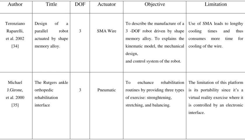
The manufactured miniature Stewart platform delivers a full drive of 12 mm in the z-axis at 55℃, with a maximum tilt angle of 30℃ in 4 s. The limitation of this study is that it has a long response time and low operating frequency. The limitation of this study is that the average failure rate of electric actuator is higher than the pneumatic actuator, due to the structural complexity of the problem, the technical requirements of the site maintenance personnel are relatively high. The system will ensure functionality, but also have small dimensions and a low mass, taking into account the physiological dimensions of the foot and lower leg.
The use of SMA leads to long cooling times and therefore consumes more time for cooling the wire. The limitation of this platform is its portability, as it is a virtual reality exercise where it is controlled by an electronic interface. The control approach for motion control of the platform is presented using an LQG which is a modern control technique.
To propose a rehabilitation device with low cost and easy to manufacture and ensure the functionality of the devices.
Critical Analysis
Summary
Introduction
- Research Flowchart
- Pneumatic Artificial Muscle Actuated Stewart Platform
- Schematic of Stewart Platform
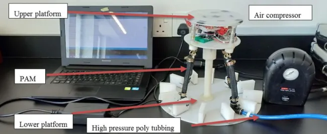
- Developed Stewart Platform Test-rig
- System Configuration
- Working Principle of Pneumatic Artificial Muscle Actuated Stewart Platform
- Materials needed for the construction of the PAM
- Preliminary Test – Force
- Material selection for proposed design
- Range of motion - Gyroscope MPU-6050
- Working principle of gyroscope MPU-6050
- Connection of gyroscope MPU-6050 to Arduino
- Force applied - Force sensing resistor (FSR 402)
- Specification of FSR 402
- Testing of FSR 402
- Working principle of force sensitive resistor (FSR)
- Research Design
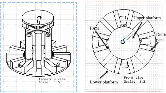
Basically, one end of the Pneumatic Artificial Muscle is connected to the upper platform and the other end is connected to the pneumatic assembly. When the Pneumatic Artificial Muscle is under pressure, the muscle will expand and contract, which leads to the displacement of the upper platform. The gyroscope is fixed between the upper platform to measure the upper angle and the force sensitive resistor (FSR-402) is fixed on top of the upper platform to measure the force applied to the platform.
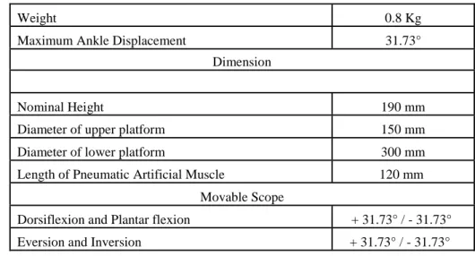
PAM selection is based on the PAM diameter from small, medium to large, which scientifically affects the angle of the platform. A range of motion reading will be displayed when the PAM is under pressure. The total height of the Stewart platform is 190 mm, and the diameter of the upper and lower platforms is 150 mm and 300 mm.
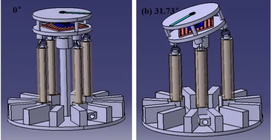
Figure 3.6 shows the Stewart platform powered by PAM for dorsi/plantar flexion and identifies the movable range of dorsiflexion and plantar flexion from 0° to 31.73° for the 12 mm PAM diameter. a) Movement in dorsiflexion (b) Movement in plantar flexion Figure 3.6: PAM powered Stewart platform for foot/ankle rehabilitation. When the PAM is under pressure, the muscle will expand and shorten, leading to displacement of the upper platform. A force test was performed to determine the pull of the PAM as shown in Figure 3.7.
To measure the pulling force of the Pneumatic Artificial Muscle, the 12 mm PAM is fixed between the load cell and the base cylinder.
Introduction
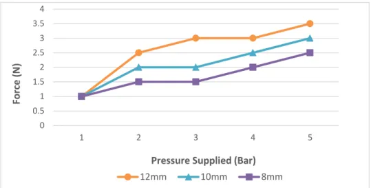
Preliminary Test-Force
It is clearly shown that the PAM with a diameter of 12 mm has a maximum tensile force of 3.5 N when PAM is pressurized to 5 bar. The PAM with the diameter of 8 mm has a tensile force of 2.5 N when PAM is pressurized to 5 bar. All three diameters of PAM have a minimum force of 1 N when pressurized to 1 bar.
According to PAM with diameter 12 mm, the difference between maximum force and minimum force is 2.5 N, followed by PAM with diameter 10 mm and 8 mm, which are 2 N and 1.5 N, respectively.
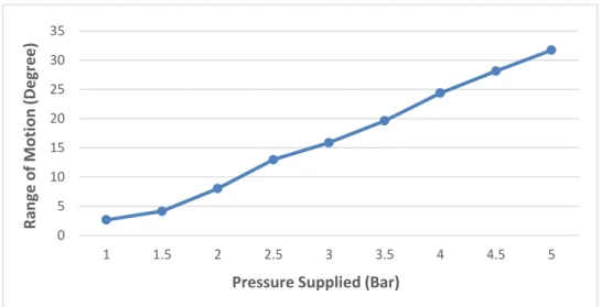
Pneumatic Artificial Muscles with the diameter of 12 mm
Based on the graph above, it is clearly seen that the maximum range of motion of the platform is 31.73° when the Pneumatic Artificial Muscles are pressurized at 5 bar. The maximum range of motion obtained is 28.84° and the minimum range of motion obtained is 2.27°. When the Pneumatic Artificial Muscle is pressurized from 1 bar to 1.5 bar, there is only a slight increase in range of motion.
According to the graph, the maximum range of motion of the platform is 24.20° when the pneumatic artificial muscles are under a pressure of 5 bar.
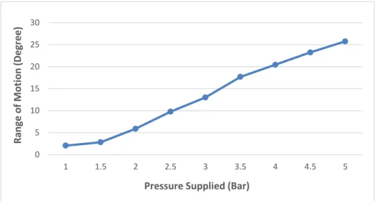
Pneumatic Artificial Muscle with the diameter of 10 mm
The maximum range of motion achieved when under 5 bar pressure is 28.62°, where there is a difference of 26.19° between the maximum and minimum range of motion. Based on the graph above, it is clear that the maximum range of motion of the platform is 25.75° when the pneumatic artificial muscles are under a pressure of 5 bar. Additionally, the graph briefly shows that the pressure delivered to the PAM is directly proportional to the range of motion of the foot/ankle.
Based on the graph above, it is clearly seen that the maximum range of motion of the platform is 22.17° when the Pneumatic Artificial Muscles are pressurized at 5 bar. The difference between the maximum and minimum range of motion is reduced when the smaller PAM diameter is used.
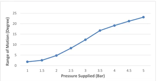
Pneumatic Artificial Muscle with the diameter of 8 mm
Based on the graph above, it is clearly seen that the maximum range of motion of the platform is 23.10° when the pneumatic artificial muscles are pressurized to 5 bar. Based on the graph above, it is clearly seen that the maximum range of motion of the platform is 20.88° when the pneumatic artificial muscles are pressurized to 5 bar.
Comparison of Range of Motion (Without Load)
Comparison of Range of Motion (Patient A)
Comparison of Range of Motion (Patient B)
Performance of Stewart Platform Prototype
Patient A's leg/ankle is applied to the platform and the angle of the platform is taken to be 31.73° and patient B is taken to have a range of motion of 24.2° for dorsiflexion movement when the PAM is pressurized to 5 bars.
Comparative Analysis
Summary
Conclusions
Recommendations for future work
Mustaffa, “A study on contraction of pneumatic artificial muscles (PAM) for load lifting,” in Journal of Physics: Conference Series, 2017, p. Parasuraman, “A review on the mechanical design elements of ankle rehabilitation robot,” Proceedings of the Institution of Mechanical Engineers, Part H: Journal of Engineering in Medicine, vol. Hannaford, “An ankle-foot orthosis actuated by artificial pneumatic muscles,” Journal of Applied Biomechanics, vol.
Goad, “Effect of Foam Rolling and Static Stretching on Passive Hip Flexion Range of Motion,” Journal of Sports Rehabilitation, vol. Ikuta, “Acute Effects of Self-Myofascial Release Using a Foam Roller on Arterial Function,” The Journal of Strength &. Beardsley, “Specific and crossover effects of foam rolling on ankle dorsiflexion range of motion,” International Journal of Sports Physical Therapy, vol.
Neumann, “Wobble board training after partial sprains of the lateral ligaments of the ankle: a prospective randomized study,” Journal of Orthopedic & Sports Physical Therapy, vol. Jensen, "Electromyographic and Kinetic Analysis of Traditional, Chain, and Elastic Band Squats," The Journal of Strength &. Li, “Toward optimal platform-based robot design for ankle rehabilitation: State of the art and future prospects,” Journal of Healthcare Engineering , vol.
Buckley, “Test-retest reliability of the Biodex System 4 Isokinetic Dynamometer for assessing knee strength in pediatric populations,” Journal of allied health, vol.
![Figure 2.3: Pneumatic Artificial Muscle (a) before contraction (b) after contraction [8]](https://thumb-ap.123doks.com/thumbv2/azpdforg/10231234.0/20.893.172.810.730.919/figure-pneumatic-artificial-muscle-before-contraction-after-contraction.webp)
![Figure 2.7: (a) Elastic band (b) Roller foam (c) Wobble foam [17-19]](https://thumb-ap.123doks.com/thumbv2/azpdforg/10231234.0/24.893.173.820.706.915/figure-elastic-band-b-roller-foam-wobble-foam.webp)
![Figure 2.8: (a) JACE Ankle A330 CPM system (b) Optiflex Ankle CPM system (c) Kinetec Breva Ankle CPM system [24, 25]](https://thumb-ap.123doks.com/thumbv2/azpdforg/10231234.0/26.893.159.798.436.657/figure-ankle-system-optiflex-ankle-system-kinetec-breva.webp)