Your Global Automation Partner
Integration Manual
excom I/O System
Integration in Honeywell
Experion via EtherNet/IP
Contents
1 About this manual ... 5
1.1 Explanation of symbols used ... 5
1.2 Other documents ... 5
1.3 Feedback about these instructions... 5
2 Notes on the system... 6
2.1 System identification... 6
2.2 Turck service... 6
3 For your safety ... 7
3.1 Intended use... 7
3.2 General safety instructions... 7
3.3 Notes on Ex protection... 7
4 Commissioning ... 8
4.1 Setting the IP address... 8
4.2 Web server — list inserted modules... 9
5 Integrating the excom system in Honeywell ... 11
5.1 Requirements... 11
5.1.1 Requirements — hardware ... 11
5.1.2 Requirements — software... 11
5.2 Installing an EDS configuration file ... 12
5.3 Creating a Honeywell Unit Operation Controller... 16
5.4 Configuring a Honeywell Unit Operation Controller ... 17
5.5 Creating an excom station... 18
5.5.1 Creating an Ethernet/IP adapter ... 18
5.5.2 Configuring an Ethernet/IP adapter... 19
5.5.3 Creating slaves... 20
5.5.4 Configuring the slave ... 21
5.5.5 Configuring the signal types... 22
5.6 Loading an excom module ... 25
5.6.1 Loading a signal... 27
5.7 Switching to monitoring... 28
5.8 Activating an excom station ... 29
5.9 HART information... 32
5.10 Reading diagnostic information... 34
6 Redundancy strategies... 38
6.1 Topology ... 38
6.2 Redundancy setup ... 38
6.3 System redundancy ... 39
7 Turck subsidiaries — contact information ... 41
Contents
1 About this manual
This manual describes the integration of the excom system in the Honeywell control system via EtherNet/IP.
Read this manual and the applicable documents carefully before the integration. This will pre- vent the risk of personal injury and damage to property. Keep this manual safe during the ser- vice life of the product. If the product is passed on, hand over this manual as well.
The possibilities for the EDS-based integration will be outlined, from the installation of the EDS through to the handling of the I/O data and the associated diagnostics. Other applications of the excom system are described in addition to the general integration:
n Setting up redundancy
n Changing parameters during operation n Changing configurations during operation
Keep these instructions safe during the service life of the product. If the product is passed on, pass on these instructions as well.
1.1 Explanation of symbols used
The following symbols are used in these instructions:
DANGER
DANGER indicates a dangerous situation with high risk of death or severe injury if not avoided.
WARNING
WARNING indicates a dangerous situation with medium risk of death or severe in- jury if not avoided.
CAUTION
CAUTION indicates a dangerous situation of medium risk which may result in minor or moderate injury if not avoided.
NOTICE
NOTICE indicates a situation which may lead to property damage if not avoided.
NOTE
NOTE indicates tips, recommendations and useful information on specific actions and facts. The notes simplify your work and help you to avoid additional work.
u
CALL TO ACTIONThis symbol denotes actions that the user must carry out.
a
RESULTS OF ACTIONThis symbol denotes relevant results of actions.
1.2 Other documents
Besides this document the following material can be found on the Internet at www.turck.com:
n Data sheet n Quick Start Guides n excom manuals n Approvals
1.3 Feedback about these instructions
We make every effort to ensure that these instructions are as informative and as clear as possible. If you have any suggestions for improving the design or if some information is missing in the document, please send your suggestions to [email protected].
Notes on the system
Turck service
2 Notes on the system
2.1 System identification
This manual applies to the Turck excom system.
2.2 Turck service
Turck supports you with your projects, from initial analysis to the commissioning of your applic- ation. The Turck product database under www.turck.com contains software tools for program- ming, configuration or commissioning, data sheets and CAD files in numerous export formats.
The contact details of Turck subsidiaries worldwide can be found on p. [} 41].
3 For your safety
The product is designed according to state-of-the-art technology. However, residual risks still exist. Observe the following warnings and safety notices to prevent damage to persons and property. Turck accepts no liability for damage caused by failure to observe these warning and safety notices.
3.1 Intended use
The excom I/O system is integrated into the Honeywell control system via EDS-based Ethernet/IP.
The devices may only be used as described in these instructions. Any other use is not in accord- ance with the intended use. Turck accepts no liability for any resulting damage.
3.2 General safety instructions
n The device may only be assembled, installed, operated, parameterized and maintained by professionally-trained personnel.
n The device may only be used in accordance with applicable national and international regulations, standards and laws.
n The device meets the EMC requirements for industrial areas. When used in residential areas, take measures to avoid radio interference.
n Only combine devices for which the technical data is suitable for joint use.
n Faulty repairs can lead to the device failing and to accidents leading to property damage and personal injury. Do not interfere with or modify the system components. These devices are not intended for repair. Take defective devices out of operation and send them to Turck for fault analysis. Observe our return acceptance conditions when returning the device to Turck.
3.3 Notes on Ex protection
n Only use the device in Ex areas when installed in the appropriate protective housing.
n Observe national and international regulations for explosion protection.
n When operating the device in a hazardous area, the user must have a working knowledge of explosion protection (IEC/EN 60079-14, etc.).
n Use the device only within the permissible operating and ambient conditions (see approval data and Ex approval specifications).
n Fit blank modules (BM1) on unused slots on the module rack.
n Cables and terminals with intrinsically safe circuits must be indicated — use light blue for color-coding. Separate cables and terminals from non-intrinsically safe circuits or isolate ac- cordingly (IEC/EN 60079-14).
n Perform "Proof of intrinsic safety".
n Never connect equipment to intrinsically safe circuits if this equipment was previously used once in non-intrinsically safe circuits.
n Cables and terminals with intrinsically safe circuits must be indicated — use light blue for color-coding. Separate cables and terminals from non-intrinsically safe circuits or isolate ac- cordingly (IEC/EN 60079-14).
n Please follow the instructions for use for the built-in equipment.
Commissioning
Setting the IP address
4 Commissioning
Requirements
n An Ethernet gateway and all required I/O modules are inserted into the module rack.
n When power is supplied by the PSM24-…: The knurled screw under the supply module is fully tightened.
n When power is supplied by the PSM24-…1: The locking cap is inserted over the module cap and fully engaged.
n The gateway must be connected to a PC.
n The Turck Service Tool must have been installed on the PC.
The device is operational automatically once the power supply is switched on. The status LED on the module flashes green and the gateway status LED flashes red.
4.1 Setting the IP address
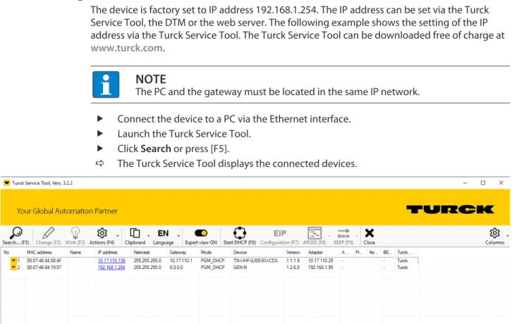
The device is factory set to IP address 192.168.1.254. The IP address can be set via the Turck Service Tool, the DTM or the web server. The following example shows the setting of the IP address via the Turck Service Tool. The Turck Service Tool can be downloaded free of charge at www.turck.com.
NOTE
The PC and the gateway must be located in the same IP network.
Connect the device to a PC via the Ethernet interface.
Launch the Turck Service Tool.
Click Search or press [F5].
a The Turck Service Tool displays the connected devices.
Fig. 1: Turck Service Tool
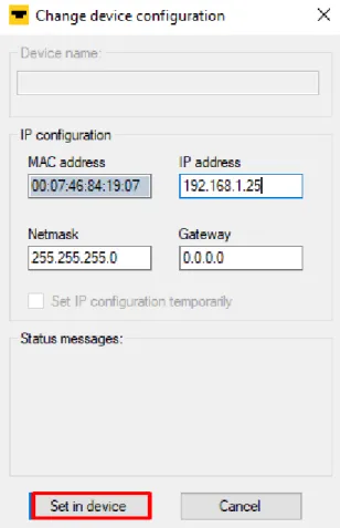
Click the gateway (example: GEN-N).
Click Change or press [F2].
Set the IP address and if necessary the network mask and gateway.
Accept the changes by clicking Set in device.
Fig. 2: Setting the IP address
4.2 Web server — list inserted modules
The device is factory set to IP address 192.168.1.254. To open the web server via a web browser, enter http://192.168.1.254 in the address bar of the web browser. If the IP address has been changed, enter the new IP address in the address bar of the web browser.
Alternatively, double-click the IP address in the Turck Service Tool.
A login is required in order to edit settings via the web server. The default password is
“password”.
NOTE
To ensure greater security, Turck recommends changing the password after the first login.
Enter the password in the Login field on the start page of the web server.
Click Login.
Commissioning
Web server — list inserted modules
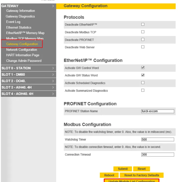
In the navigation bar on the left, select Gateway
Ò
Gateway Configuration. Click Update Module List Configuration.
a All modules are listed in the navigation bar on the left-hand side. The Status LED on the module is green. The input and the output LEDs light up in red or yellow depending on the type of module and the configuration. Further information can be found in the manuals.
Fig. 3: Gateway Configuration — Update Module List Configuration
5 Integrating the excom system in Honeywell
5.1 Requirements
5.1.1 Requirements — hardware
This example uses the following hardware:
Honeywell hardware
n Honeywell Unit Operations Controller: ControlEdge 900 platform
Turck hardware
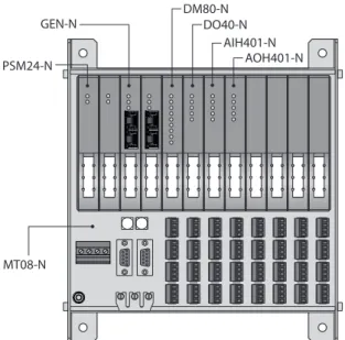
n MT08-N module rack n GEN-N gateway
n DM80-N digital I/O module n DO40-N digital output module n AIH40-N analog input module n AOH40-N analog output module n Ethernet cable
PSM24-N GEN-N
DM80-N DO40-N
AIH401-N AOH401-N
MT08-N
Fig. 4: Example setup of the excom station
5.1.2 Requirements — software
This example uses the following software:
Honeywell software
n Honeywell Experion R511 n EDS configuration file
Turck software
n Gateway firmware V1.2.25.5
Integrating the excom system in Honeywell
Installing an EDS configuration file
5.2 Installing an EDS configuration file
NOTE
Honeywell provides the EDS configuration file for the excom system as a zip file.
The configuration files describe the scope of configuration and the communication properties of an EtherNet/IP participant. To configure the excom station, the EDS configuration file must be integrated into the hardware configurator of the host system. This provides the EtherNet/IP master with the valid information and data records for the excom station during system config- uration.
Open Configuration Studio 4.0.
Establish a connection to the Experion server.
Select Control Strategy from the navigation bar on the left-hand side.
Click Configure process control strategies.
Fig. 5: Opening the Control Builder
a The Control Builder opens.
Importing an EtherNet/IP library
Unzip the zip file to a local folder.
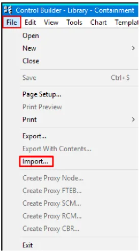
Select File
Ò
Import… in the Control Builder.Fig. 6: Select Control Builder — Import…
Integrating the excom system in Honeywell
Installing an EDS configuration file
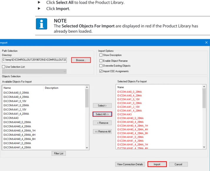
Click Browse… and select the appropriate file.
Click OK.
Click Select All to load the Product Library.
Click Import.
NOTE
The Selected Objects For Import are displayed in red if the Product Library has already been loaded.
Fig. 7: Importing a Product Library
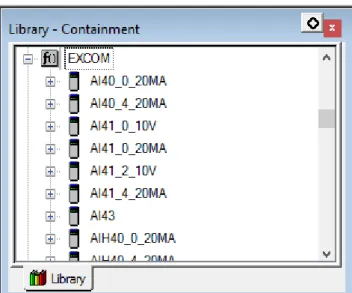
a The Product Library with the excom modules appears in the Library – Containment window.
Fig. 8: Modules in the Library – Containment window
Integrating the excom system in Honeywell
Creating a Honeywell Unit Operation Controller
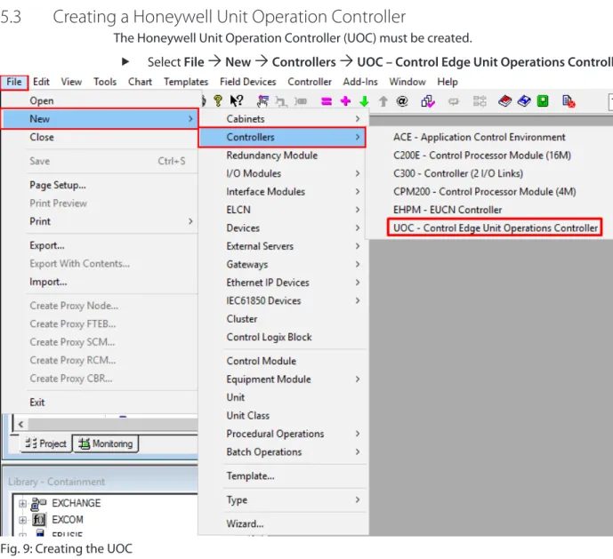
5.3 Creating a Honeywell Unit Operation Controller
The Honeywell Unit Operation Controller (UOC) must be created.
Select File
Ò
NewÒ
ControllersÒ
UOC – Control Edge Unit Operations Controller.Fig. 9: Creating the UOC
a The UOC has been created.
5.4 Configuring a Honeywell Unit Operation Controller
The Honeywell Unit Operation Controller must be configured.
NOTE
The last three digits of the IP address must be between 101 and 253.
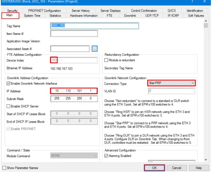
Double-click UOC…
Under Main
Ò
Device Index, set the last three digits of the IP address (here: 103). Under Downlink Address Configuration, set the IP address range of the excom gateway (here: 10.110.101.1).
Under Connection Type select Star-PRP (star topology).
Confirm with OK.
Fig. 10: Configuring the UOC
a The UOC has been configured.
Integrating the excom system in Honeywell
Creating an excom station
5.5 Creating an excom station
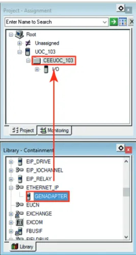
5.5.1 Creating an Ethernet/IP adapter
The excom system Ethernet/IP adapter must be created as a slave of the UOC.
Drag the EtherNet/IP adapter (here: GENADAPTER) from the Library – Containment window to the Project – Assignment
Ò
CEEUOC… window.Fig. 11: Creating an EtherNet/IP adapter using drag-and-drop a The EtherNet/IP adapter has been created.
5.5.2 Configuring an Ethernet/IP adapter
For the Honeywell controller to communicate with the excom station, the excom gateway must be configured.
Under Project – Assignment
Ò
expand the UOC… section. Double-click GENADAPTER.
a The configuration window opens.
Select Main.
Under Tag Name, assign a name to the EtherNet/IP adapter (here: excom-demo).
Under IP address of the device, set the IP address of the gateway.
Under Chassis Size, enter the number of slots in the excom station plus one (+1) (e.g. for MT08-N: 9 slots).
Confirm with OK.
Fig. 12: Configuring an Ethernet/IP adapter
a The EtherNet/IP adapter has been configured.
Integrating the excom system in Honeywell
Creating an excom station
5.5.3 Creating slaves
The excom station modules must be created as slaves.
Drag and drop the configuration for the respective module from the Library – Contain- ment window to the Project – Assignment
Ò
excom station window (here: excom demo).5.5.4 Configuring the slave
In the Project – Assignment window, double-click the module (example: DM80-N).
a The configuration window opens.
Select Main.
Under Tag Name, assign a name to the module.
Under Extended Path to Device, enter the number of the slot in which the module is inserted in the excom station.
Optional: Change the parameters under Channel Configuration.
Confirm with OK.
Fig. 14: Configuring the slave — entering the slot
a The slave has been configured.
Integrating the excom system in Honeywell
Creating an excom station
5.5.5 Configuring the signal types
The signal types must be configured to allow communication with the excom system and the Honeywell controller.
In the Project – Assignment window, expand the module (here: AIH40_20MA_8H_229).
Right-click the desired channel (here: SPARE_01).
Select the signal type by double-clicking on it under Channel Type Setting.
Fig. 15: Creating a signal
a The configuration window opens.
Select Main.
Activate HART: Check the Enable HART option.
Optional: Under Tag Name, assign a name to the signal.
Confirm with OK.
Fig. 16: Activating HART
Integrating the excom system in Honeywell
Creating an excom station
Loading a configuration
Right-click UOC…
Click Load With Contents...
Fig. 17: Loading a configuration
5.6 Loading an excom module
In the Project – Assignment window, right-click the excom station (here: CEEUOC_103).
Click Load With Contents…
Fig. 18: Right-clicking excom modules a The Load Operation window opens.
Integrating the excom system in Honeywell
Loading an excom module
Click Load.
Fig. 19: Loading an excom module
a The excom station is loaded with the full tree structure.
5.6.1 Loading a signal
Each module signal must be created individually.
Right-click the desired signal in the Project – Assignment window.
Click Load…
Fig. 20: Loading a signal a The signal is loaded.
Load additional signals according to the individual configuration.
a The planning for the excom station and the modules is complete. The corresponding data has been uploaded to the Honeywell controller.
Integrating the excom system in Honeywell
Switching to monitoring
5.7 Switching to monitoring
Monitoring is a live view of the Honeywell controller. The excom station and modules must first be activated in order to start the controller.
Click Monitoring.
Fig. 21: Switching to Monitoring
5.8 Activating an excom station
The excom station must be activated.
In the Monitoring – Assignment window, right-click the excom station (here: excom- demo).
Click Load With Contents...
Fig. 22: Activating an excom station a The Load Operation window opens.
Integrating the excom system in Honeywell
Activating an excom station
Check the Change state to Post-Load State after load option.
Click Load.
Fig. 23: Load Operation window
Starting the Honeywell controller
The Honeywell controller must be started after activating the excom station.
Double-click in the Monitoring – Assignment
Ò
CEEUOC… window. Under Main
Ò
CEE StateÒ
select COLDSTART or WARMSTART.a A query window opens.
Click Yes in the query window.
Confirm with OK.
a The excom station is online. The excom station and modules are marked in green.
Fig. 24: Online excom station
Integrating the excom system in Honeywell
HART information
5.9 HART information
The HART information can be read.
In the Monitoring – Assignment window, double-click the channel (here: 01: AI_01).
Fig. 25: Opening the desired channel
HART information and errors can be viewed in the upper menu bar under HART Configuration, HART Device Status, HART Identification and HART Variables.
Fig. 26: Example — HART Identification window
Integrating the excom system in Honeywell
Reading diagnostic information
5.10 Reading diagnostic information
The diagnostic information can be viewed in two ways:
n Alarms n Data/Status
Diagnostic information — alarms
For Alarms, the diagnostic information is also displayed on the Honeywell Experion Station.
In the Monitoring – Assignment window, double-click the module (here:
DM80_S_8I_215).
Fig. 27: Example — double-click the DM80-S module
a The configuration window opens.
Select Alarms.
Fig. 28: Diagnostic information — clicking Alarms
a Active diagnostics are marked with a check mark. In the example above, there is no input signal on channels 3…8 or the wire-break monitoring diagnostics is active.
Integrating the excom system in Honeywell
Reading diagnostic information
Diagnostic information — Data/Status
In the Monitoring – Assignment window, double-click the module (here:
DM80_S_8I_215).
Fig. 29: Example — double-click the DM80-S module a The configuration window opens.
Select Data/Status.
Fig. 30: Diagnostic information — clicking Data/Status
a Active diagnostics are marked with a check mark. The module-related diagnostics are dis- played for each channel. The left-hand column shows the available channels. The other columns indicate which diagnostics are active on each of the channels.
Redundancy strategies
Redundancy setup
6 Redundancy strategies
6.1 Topology
The general topology of the Turck-specific system redundancy with the Ethernet protocols EtherNet/IP, Modbus TCP and PROFINET has the following structure:
DCS DCSDCS DCSDCS
Fig. 31: System redundancy with one master and two gateways
Fig. 32: System redundancy with two masters and two gateways
The system redundancy with one master and two gateways is a Turck-specific, parameterizable redundancy function of the excom system. The two gateways are provided here with separate IP addresses. The separate IP addresses are used to set up independent communication. The gateways transmit the input data and receive the output data via the IP addresses. One gate- way is the primary gateway while the second gateway acts as a backup. If the primary gateway fails, a bumpless switchover to the backup gateway is carried out automatically. The redund- ancy function makes it possible to implement interruption-free communication. The output word of the gateway enables the forcing of a redundancy switchover.
When system redundancy is implemented with two masters and two gateways, two independ- ent Ethernet masters communicate with the associated gateway. Both masters can be con- trolled via one or two process control system controllers. The process data is processed via two separate and independent Ethernet connections to the excom system.
6.2 Redundancy setup
NOTE
Both gateways must have the same configuration, parameterization and firmware.
The Redundancy mode gateway parameter must be set for system redundancy.
6.3 System redundancy
NOTE
Both gateways must have the same configuration, parameterization and firmware.
If the Redundancy mode parameter is set to System redundancy in the DTM, web server or control system, the excom station operates in system redundancy mode. Both gateways com- municate with their respective master. The PRIO LED is lit on the active gateway. The active gateway takes over the output data transferred by the master and sends this to the output modules.
The gateway communicating with the secondary master ignores the received output data as the secondary module does not have write access to the output modules.
The gateway is provided with one input word and one output word for monitoring redund- ancy. The input word describes the current state of the gateway.
The output word is used for the manual redundancy switchover in the master. It is possible to switch in the process control system from the primary gateway to the secondary gateway.
A switchover is carried out in response to the following events:
n The primary gateway was removed.
n Communication to the primary gateway was interrupted. The outputs are set to 0 until the switchover to the other gateway is completed. After the timer for interrupted connections has elapsed, the switchover to the other gateway is carried out.
After a switchover, an automatic switchover to the former primary gateway is no longer carried out.
When the excom system is started, the gateway on the left starts to operate as the primary gateway. If communication with the left gateway fails, the gateway on the right tries to establish primary communication.
Assignment of the gateway process data bits
The input word of the gateway process data is used to view the gateway and system redund- ancy of the excom station:
Bit
Status bit 7 6 5 4 3 2 1 0
0 Not used Left
power sup- ply module
Right power sup- ply module
Gateway redund- ancy
Gateway slot
Redund- ancy status
1 Not used
Redundancy strategies
System redundancy
Meaning of the gateway process data bits
Designation Meaning
Left power supply unit 0: Left power supply unit not present 1: Left power supply unit fitted Right power supply unit 0: Right power supply unit not present
1: Right power supply unit fitted
Gateway redundancy 0: Redundant gateway or redundant communication not available 1: Redundancy available
Slot 0: Gateway is located on the right slot (GW2) 1: Gateway is located on the left slot (GW1) Active/ passive 0: Gateway is passive
1: Gateway is active
Assignment of the command bits
The output word of the gateway makes it possible to force a redundancy switchover in the
“Red switching” web server:
Bit
Byte 7 6 5 4 3 2 1 0
0 Not used Control bit Redund-
ancy switchover is initiated
Activation of the right or left gateway Control bits for edge
change
1 Not used
Meaning of the command bits
Designation Meaning
Bit 2 = 0
Redundancy switchover is initiated 11
Ò
01: Receiver is the passive gateway. The passive gateway requests control from the active gateway and becomes active.11
Ò
10: Receiver is the active gateway. The active gateway gives control to the passive gateway and becomes passive.Bit 2 = 1
Activation of the right or left gateway 11
Ò
01: Receiver is the left gateway. The left gate- way requests control from the right gateway and becomes active.11
Ò
10: Receiver is the right gateway. The right gateway requests control from the left gateway and becomes active.From gateway firmware version 1.4, the gateways support PROFINET S2 redundancy.
7 Turck subsidiaries — contact information
Germany Hans Turck GmbH & Co. KG
Witzlebenstraße 7, 45472 Mülheim an der Ruhr www.turck.de
Australia Turck Australia Pty Ltd
Building 4, 19-25 Duerdin Street, Notting Hill, 3168 Victoria www.turck.com.au
Belgium TURCK MULTIPROX
Lion d'Orweg 12, B-9300 Aalst www.multiprox.be
Brazil Turck do Brasil Automação Ltda.
Rua Anjo Custódio Nr. 42, Jardim Anália Franco, CEP 03358-040 São Paulo www.turck.com.br
China Turck (Tianjin) Sensor Co. Ltd.
18,4th Xinghuazhi Road, Xiqing Economic Development Area, 300381 Tianjin
www.turck.com.cn
France TURCK BANNER S.A.S.
11 rue de Courtalin Bat C, Magny Le Hongre, F-77703 MARNE LA VALLEE Cedex 4
www.turckbanner.fr Great Britain TURCK BANNER LIMITED
Blenheim House, Hurricane Way, GB-SS11 8YT Wickford, Essex www.turckbanner.co.uk
India TURCK India Automation Pvt. Ltd.
401-403 Aurum Avenue, Survey. No 109 /4, Near Cummins Complex, Baner-Balewadi Link Rd., 411045 Pune - Maharashtra
www.turck.co.in
Italy TURCK BANNER S.R.L.
Via San Domenico 5, IT-20008 Bareggio (MI) www.turckbanner.it
Japan TURCK Japan Corporation
Syuuhou Bldg. 6F, 2-13-12, Kanda-Sudacho, Chiyoda-ku, 101-0041 Tokyo www.turck.jp
Canada Turck Canada Inc.
140 Duffield Drive, CDN-Markham, Ontario L6G 1B5 www.turck.ca
Korea Turck Korea Co, Ltd.
B-509 Gwangmyeong Technopark, 60 Haan-ro, Gwangmyeong-si, 14322 Gyeonggi-Do
www.turck.kr
Malaysia Turck Banner Malaysia Sdn Bhd
Unit A-23A-08, Tower A, Pinnacle Petaling Jaya, Jalan Utara C, 46200 Petaling Jaya Selangor
www.turckbanner.my
Turck subsidiaries – contact information
Mexico Turck Comercial, S. de RL de CV
Blvd. Campestre No. 100, Parque Industrial SERVER, C.P. 25350 Arteaga, Coahuila
www.turck.com.mx Netherlands Turck B. V.
Ruiterlaan 7, NL-8019 BN Zwolle www.turck.nl
Austria Turck GmbH
Graumanngasse 7/A5-1, A-1150 Wien www.turck.at
Poland TURCK sp.z.o.o.
Wroclawska 115, PL-45-836 Opole www.turck.pl
Romania Turck Automation Romania SRL
Str. Siriului nr. 6-8, Sector 1, RO-014354 Bucuresti www.turck.ro
Russian Federation
TURCK RUS OOO
2-nd Pryadilnaya Street, 1, 105037 Moscow www.turck.ru
Sweden Turck Sweden Office
Fabriksstråket 9, 433 76 Jonsered www.turck.se
Singapore TURCK BANNER Singapore Pte. Ltd.
25 International Business Park, #04-75/77 (West Wing) German Centre, 609916 Singapore
www.turckbanner.sg South Africa Turck Banner (Pty) Ltd
Boeing Road East, Bedfordview, ZA-2007 Johannesburg www.turckbanner.co.za
Czech Republic TURCK s.r.o.
Na Brne 2065, CZ-500 06 Hradec Králové www.turck.cz
Turkey Turck Otomasyon Ticaret Limited Sirketi
Inönü mah. Kayisdagi c., Yesil Konak Evleri No: 178, A Blok D:4, 34755 Kadiköy/ Istanbul
www.turck.com.tr
Hungary TURCK Hungary kft.
Árpád fejedelem útja 26-28., Óbuda Gate, 2. em., H-1023 Budapest www.turck.hu
USA Turck Inc.
3000 Campus Drive, USA-MN 55441 Minneapolis www.turck.us