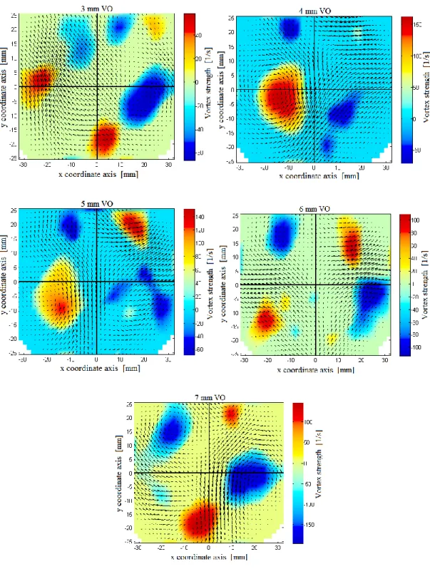
64 Figure 3.20 Flame contours at different times after initiation of ignition (dimensions not properly scaled for illustration purposes). 72 Figure 4.4 Vortices created on a vortex plane 40 mm downstream of valve seats at moderate toggle induction at variable valve heights.
INTRODUCTION
- Motivation
- Problem Statement
- Objective of the Research
- Dissertation Outline
However, there has been no extensive investigation of the early flame for direct injection CNG combustion in an actual engine. It also discusses in detail the influence of ignition energy and flow turbulence on the early flame characteristics of a spark-ignited combustion system.
LITERATURE REVIEW
Natural Gas Combustion and Emission
- Lean Combustion
- Laminar Burning Velocity
The lean or rich level of the fuel/air mixture is measured using a normalized value that may be appropriate for all fuel types. The magnitude of the laminar burning velocity of a fuel/air mixture depends on its equivalence ratio, unburned gas pressure, and temperature.
![Figure 2.1 Emissions in SI combustion as function of fuel/air mixture [14]](https://thumb-ap.123doks.com/thumbv2/azpdforg/10269098.0/28.892.305.536.583.861/figure-emissions-in-combustion-function-fuel-air-mixture.webp)
Ignition and Flame Initiation in SI Engine
- Ignition Process
- Combustion Process
This ultimately reduces or avoids heat losses that can occur due to the contact of the ignition core with the electrodes. The design of the spark plug insulation can reduce the heat losses due to contact of the early flame with the cold electrodes.
![Figure 2.3 Schematic of voltage, current and energy variations in the different phases of conventional ignition system, taken from [14]](https://thumb-ap.123doks.com/thumbv2/azpdforg/10269098.0/32.892.297.569.646.1004/figure-schematic-voltage-current-variations-different-conventional-ignition.webp)
Experimental Flame Visualization Techniques
- Fiber-Optics Instrumented Spark Plug
- Chemiluminescence Measurement Technique
- Laser Diagnostics Measurement
- Schlieren Technique
- Direct Visualization
A sapphire window was placed to protect the fibers from the direct heat of the combustion gases as shown in Figure 2.6. A pulsed laser with a wavelength of 532 nm can be used to illuminate the seed particles.
![Figure 2.6 The improved design of fiber-optics instrumented spark plug [24]](https://thumb-ap.123doks.com/thumbv2/azpdforg/10269098.0/38.892.277.592.109.313/figure-improved-design-fiber-optics-instrumented-spark-plug.webp)
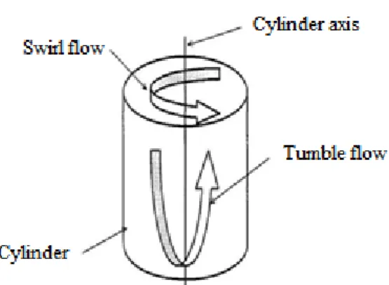
In-cylinder Flow and Mixture Formation
In a practical engine, the intake flow structure can be complex depending on the position of the intake valves, the geometry of the intake port and the angle of rotation. During the compression process, the intake flow structures undergo significant changes from the breakdown of the large-scale flow into smaller-scale turbulent eddies.
Early Flame Development in SI Engine Combustion
- Modeling of the Early Flame Kernel
- Effect of Ignition Energy on Flame Kernel Formation and Growth
- In-cylinder Turbulence and Early Flame Interaction
The zero-dimensional model is hardly used because it cannot relate combustion to cylinder flow and combustion chamber geometry. Therefore, the modeling strategies of these two processes are different, and the result of the first one will be the initial condition for the later one. They showed schlieren images of early flame cores using TCI and CDI ignition systems for stoichiometric and air-fuel ratios.
Flame growth rate in the early development stage is highly influenced by in-cylinder flow around the flame, and the quality of the combustion cycle can also be determined within this short duration of combustion after ignition initiation [5], [6]. The component depends on the macrostructure of the inlet flow (tumbling or swaying), and the magnitude of squish flow that is also generated during the compression process. The study showed that the consumption rate of the vortex toroid through the flame pit.
They showed that a threefold increase in flame growth rate was noted with a vortex interaction of the early flame than without the interaction. In the early interaction regime, a vortex pair with a core size larger than the flame kernel interacted with the core and the result showed a global or local extinction of the small flame kernel, while in the later time, the interaction of the vortex pair with a larger flame kernel caused ripple effects on the flame front. In this study, it was noted that the flame was stretched and the growth rate increased depending on the translational speed of the vortex pair to the flame in the later regime.
Summary
EXPERIMENTAL METHODS AND ANALYSIS TECHNIQUES
Equipment for Flame and Flow Visualizations
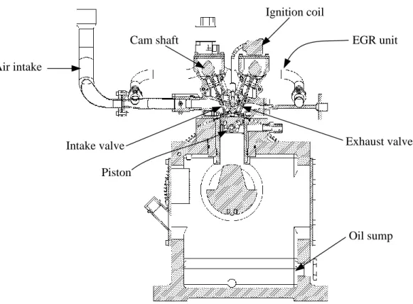
- Optical Engine
- Fuel Injection System
- Ignition System
- Endoscopes
- Imaging Device
- Illumination System
- Seed Generator
The ignition system consists of the DC power supply, ignition coil and an M12 spark plug. The arrangements of the endoscopic access lines are shown in the schematic of the motor assembly in Figure 3.4. On the other hand, the light sheet endoscope was placed orthogonally from the camera endoscope (on the back of the motor unit, Figure 3.4) and at an installation angle of 16o from the horizontal plane.
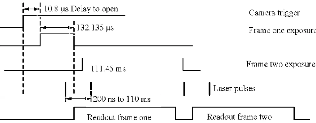
An image intensifier is a must-have tool to increase the intensity and increase the faint luminescence of the flame you want to capture. The maximum frame rate of the camera in single-frame mode is only 9 Hz, which will be half of that in dual-frame mode. It consists of two laser heads responsible for emitting two laser pulses (Figure 3.8).
Analyzing the velocity and turbulence of fluid flows using the PIV system requires seeding the flowing fluid with appropriate seed particles. In its current sense, the PIV system is used to measure the velocity of particles in liquid. Therefore, certain criteria must be expected from the seed particles in order for their flow to represent the fluid velocity.
Cylinder Head Assembly for Intake Flow Characterization
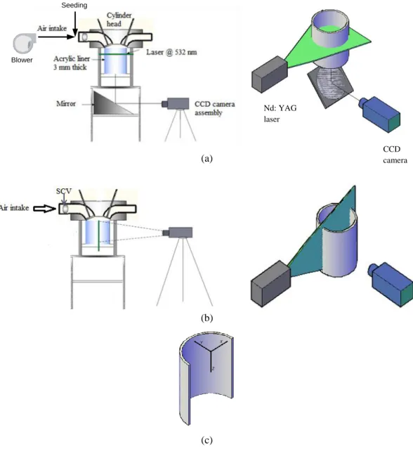
- Experimental Setup
- Intake flow Analysis Technique
- Pre-processing and Cross-correlation
- Post-processing and Derivation of Flow Parameters
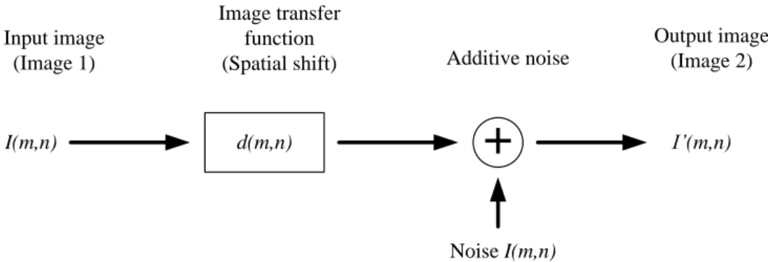
This event has the ability to generate high levels of turbulence in the engine cylinder. The PIV system is a whole field velocity and turbulence measurement technique that tracks the movement of seeded particles in the flow. In the digital signal processing model, I'(m,n) can be considered as the output of an image transfer function d(m,n), taking I(m,n) as input.
Another function, the narrow-width low-pass filter function, was also applied to the output of the correlation process in the frequency domain before the FFT and inverse. In the moving average estimation method, the average of the neighborhood vectors that can be calculated from equation 3.3 should be compared with the target vector under consideration. The torque can be identified and placed in the flow field using the local velocity gradient tensor and its corresponding eigenvalue.
The imaginary part of the eigenvalue of the gradient sensor given in equation 3.6 can precisely locate a swirling vortex in the flow field. A region of the flow field that has negative values for the square root expression of equation 3.8 would demonstrate the presence of a swirling vortex. Therefore, the magnitude of the eddy strength can be accurately identified from the imaginary part of the eigenvalue, as elaborated in [54].
Early flame Development Experimental Setups and Analysis Methods
- Flame Imaging Experimental Setup
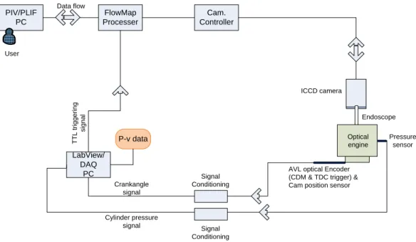
- Data Acquisition System
- Flame Analysis Technique
- Gaussian Filter
- Image Binarization
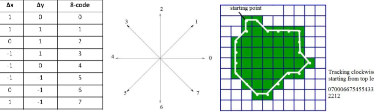
- Flame Boundary Tracing
- Chain Coding and Elliptic Fourier Representation of Flame
- Derived Parameters to Measure Flame Development
- Fuel Mass Burn Analysis
The Gaussian kernel for a 2-D representation can be given by;. 3.12) where defines the width of the Gaussian kernel or the standard deviation. For edge pixels, zero padding can be used to place those pixels in the center of the filter kernel. The derivation of the algorithm started by representing the intensity of the image pixels with L gray levels, and which can be given in the range i, i+1, …, L].
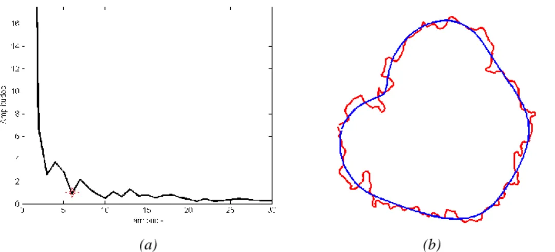
Assuming that the number of pixels in level i is denoted by hi and the total number of pixels is denoted by N. The probability distribution of the gray level of the pixels can be given by Eq. Finally, N x 2 vertices can be collected to define the outer contour of the flame for further analysis; where N is the total number of points describing the contour. N is the total number of Fourier harmonics required to generate an accurate approximation of the flame boundary.
This technique was found to be effective for approximating the average flame contour in the study by avoiding the details of the curves. The rotation invariance function can be used in the analysis to align the semimajor axis of the first harmonic with the positive x-axis. In other words, the coefficients can be changed only by changing the shape of the closed contour.
RESULTS AND DISCUSSIONS
- Introduction
- Intake Flow Analysis
- Swirl Plane Analysis
- Tumble Plane Analysis
- PIV Measurement Validation
- Early Flame Analysis and Discussion
- Stratified and Homogeneous Combustion
- Flame Wrinkles
- Flame Distortion
- Flame Position and Displacement
- Flame Growth Rate
- Combustion Performance and its Relationship with Flame Growth Rate
- Fuel burn Fraction
- Peak Cylinder Pressure
- NO x Formation
- Summary
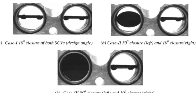
The positions of the adjustable valve in the SCVs for the three different adjustment cases are shown in Figure 4.1. This can be observed from the streamlines and eddy strength maps of the airflow just downstream of the flaps, shown in Figure 4.2. The swirling flows created are observed in Figure 4.2 (b) and (c) just downstream of the left valves in medium swirl and high swirl adjustments.
However, there was no clearly identified coherent eddy structure in this induction strategy even further downstream as shown in Figure 4.3. a) Streamlines and located vortices 10 mm downstream from valve seats. Therefore, there would be formations of many small vortex cores on the vortex plane of the medium tumbling induction process. This circulating current increased its core size downstream in the cylinder and it was also tilted to the other side of the cylinder, as shown in Figure 4.5.
In this case, the average spin induction showed a solid and compact core with a velocity of 2.7 m/s at the periphery of the core. The nuclear center had a displacement from the center of the ellipse along the major axis. The rotational axis considered was the axis passing through the center of the core of rotation.
CONCLUSIONS AND FUTURE WORK
Conclusion
- Stratified Combustion Case
- Homogeneous Combustion Case
- Performance Parameters
Therefore, the early flame with the high level of vortex induction (medium vortex and high vortex) was displaced into the side of the bowl, which had some offset from the cylinder axis. The combined effect of the analyzed flame parameters in the stratified combustion resulted in a higher flame expansion rate for medium tumbling induction. High vortex induction was observed to have better wrinkling ability of the early flame and medium vortex was the least to form wrinkles on the flame surface.
But the flame position in medium swirl and high swirl induction boxes was more compactly located close to the spark center and completely located on one side of the cylinder part (where the piston cup center is located). The influence of the variable parameters resulted in high flame development rate for the high vortex induction case of the homogeneous combustion. Nakamura, "A Study of Combustion and Emission Characteristics of Compressed-Natural-Phase Direct Injection Stratified Combustion Using a Rapid-Compression Engine".
Arndt, “Analysis of the temporal flame core development in an optically accessible IC engine using high-speed OH-PLIF,” Applied Physics B, vol. Khani, "A Developed Quasi-Dimensional Combustion Model in Spark-Ignition Engines," in Proceedings of the World Congress on Engineering, London, 2008. Tort, "Elliptic Fourier functions as a morphological descriptor of the genus Stenosarina (Brachiopoda, Terebratulida, New Caledonia,” International Association for Mathematical Geology, vol.
Future work
![Figure 2.2 Laminar flame velocity of variable equivalent ratio natural gas as functions of pre-ignition temperature and pressure [16]](https://thumb-ap.123doks.com/thumbv2/azpdforg/10269098.0/30.892.256.581.102.484/laminar-velocity-variable-equivalent-functions-ignition-temperature-pressure.webp)
![Figure 2.8 Velocity vectors (arrows), concentration fields (colored region) and flame region [33]](https://thumb-ap.123doks.com/thumbv2/azpdforg/10269098.0/42.892.296.670.762.1055/figure-velocity-vectors-arrows-concentration-fields-colored-region.webp)