The author studied the effect on the performance of a DC motor by replacing a ferrite magnet with the melt-spun NdFeB magnet. In this project, the author fabricated a bonded NdFeB for a DC motor from NdFeB alloy powders produced via the melt spinning process. The magnet is manufactured using compression molding technology and epoxy as a binder.
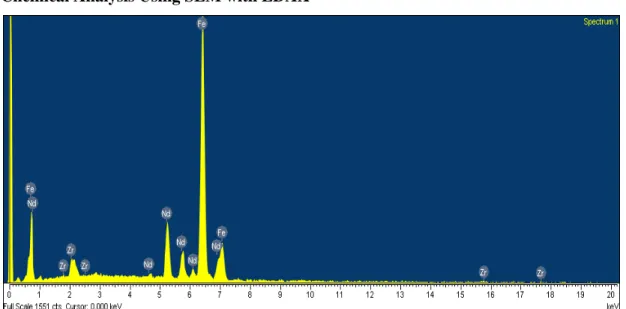
In addition, the microstructure and chemical properties of the magnet are checked using optical microscopy and also scanning electron microscopy (SEM) with chemical analysis. This result shows that by replacing the ferrite magnet with the bonded NdFeB magnet it is able to build a more efficient motor.
Background of Study
Problem Statement
The advantage of these properties is that a unit that can be built using a magnet is a smaller, lighter and more efficient unit designed to produce a wide range of applications.
Objectives and Scope of Study
Prospect of NdFeB Magnet in Market
Current Trends
Market Drivers
Magnet
- Magnetism
- Magnetic Induction
- Magnetic Permeability and Susceptibility
- Type of Magnetism
- Magnetization and Demagnetization of a Ferromagnetic
- Parameter to describe magnetization curve
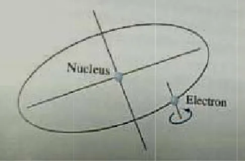
When a ferromagnetic material is placed in an applied magnetic field, the intensity of the magnetic material field will be increased. The increase in magnetization is measured by a quantity called magnetic permeabilityμ, which is defined as the ratio of the magnetic induction B to the applied field H, or. Magnetic fields and forces arise from the movement of the basic electric charge, the electron.
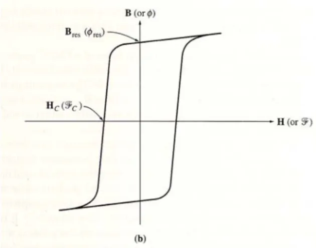
Let us then apply a magnetizing field to the sample and observe the effect of the applied field on the magnetic induction of the sample. When the reverse field is removed, the magnetic induction will return to the remanent induction at point F in the figure and upon application of the positive applied field, the B-H curve will follow FGA to complete a loop.
Design Advantages and Advancement using NdFeB magnet 22
- Energy product, BH max
- Temperature Coefficient
- Magnetizing force
- Curie Temperature
- Thermal Expansion
- Cost
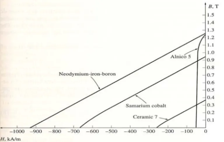
When considering the amount of magnet material required in a given device, a high energy material is always preferable. Given a certain flux required at a fixed distance from the magnet, we can use this information to estimate what volume will be required for different magnet materials. This means that the volume of Ceramic 5magnet should be 9.7 times larger than the size of the Neo 35.
Therefore, in addition to the cost savings from using less NdFeB material than other magnet For comparing the same common magnet in the industry, the chart below shows the maximum energy rating of the NdFeB magnet and other competitors' magnets. The magnet specification may be given at one temperature (typically 20oC) and the designer must consider the effect of the operating temperature range on performance. The magnetizing force recommended by the magnet manufacturer is the external magnetic force that must be applied to the material to fully saturate it.
The operating temperature of magnetic material is well below this value and is primarily determined by how much performance degradation is acceptable compared to that at room temperature. This process is required if the magnet is to be remagnetized or magnetized differently from the previous state. It is therefore easier to demagnetize an NdFeB magnet than other magnets with an intermediate temperature furnace.
NdFeB magnet material has thermal expansion coefficient of about half that of SmCos. This means that for a given temperature range, an NdFeB magnet will experience a much smaller change in dimension than a SmCo magnet of the same dimension. The amount of this change is important in determining the fit between the magnet and the surrounding materials.
![Figure 2.7: Comparison of NdFeB magnet maximum energy with other competitor in market in Mg.Oe [2]](https://thumb-ap.123doks.com/thumbv2/azpdforg/10269534.0/23.918.284.698.486.720/figure-comparison-ndfeb-magnet-maximum-energy-competitor-market.webp)
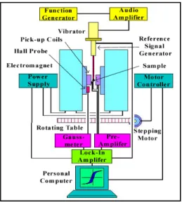
Vibrating Sample Magnetometer (VSM)
However, by using a more powerful magnet, the entire device into which the magnet is inserted can be miniaturized, saving costs that favor stronger magnetic materials.
Epoxy Binder
Binder
Epoxy Resins
Epoxy Hardeners
The chemical properties of epoxy resins that affect epoxy hardeners are: the amount of viscosity and the type of thinners and fillers in the epoxy resins. The physical characteristics of the epoxy resin system that affect the behavior of epoxy hardeners in the epoxy resin system are the temperature of the work area, the temperature of the resin system, and humidity [22].
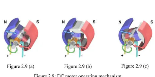
DC Motor Operating Mechanism
Permanent Magnet DC Motor
PMDC motors are especially common in smaller fractional and subfractional horsepower sizes, where cost and space of a separate field circuit cannot be justified. Permanent magnets cannot produce as high a flux density as an externally supplied shunt field, so a PMDC motor will have a lower induced torque τ ind per ampere ampere of amature current IA than a shunt motor of the same size and construction. The amature mmf subtracts from the mmf of the poles below other portions of the poles' faces, reducing the overall net flux of the machine.
In a PMDC motor, the full current is only the residual current in the permanent magnets. If the armature current becomes very large, there is some risk that the armature mmf will demagnetize the poles, permanently reducing and diverting the remaining current into them. A good PMDC motor pole material should have as high a residual Bres as possible, while at the same time having as high a coercive magnetic strength Hc as possible.
The large Bres produces a large flux in the machine, while the large Hc means that a very large current would be required to demagnetize the poles. First, several literatures were collected to analyze the data and obtain the necessary knowledge about the composition of magnets, technique for manufacturing high energy product of bonded NdFeB magnet and to study the characteristics of the binders that will be used. Second step, to identify the material and consumables needed for this project such as epoxy that would be used to mix with the magnetic powder.
The necessary materials were then purchased and manufactured, such as a mold for the experiment. Types of experiments that would undergo further analysis such as hardness tests, density measurements and magnetic properties analysis conducted at SIRIM. At the end of the preparatory work, the requirements, advantages and disadvantages of the energy product of a bonded NdFeB magnet were defined.
Planning
In addition to literature reviews, the Internet including message boards, websites, and electronic books and journals were used to find additional information and references.
Study and Research
Equipments and Tools familiarization
Procedures for Fabricating Bonded NdFeB Magnet
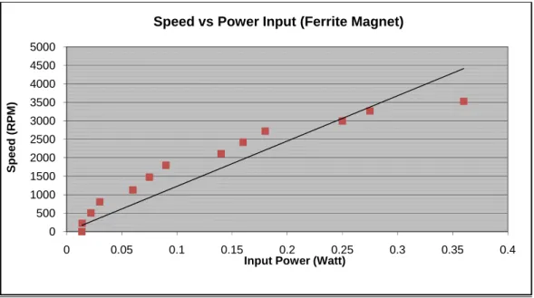
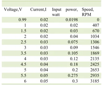
The input power of the motor was changed by regulating the voltage of the power supply. Obviously, we can see that using a NdFeB magnet increases the speed of the DC motor. It begins to rotate when the armature's magnetic field is able to overcome the strong magnetic field of the permanent magnet.
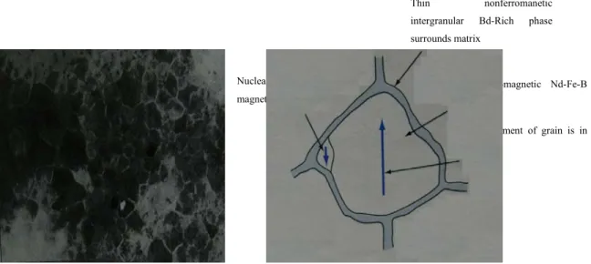
The SEM image also shows the grain size of the NdFeB alloy, which is about 20 to 50 µm. This is due to the rapid quenching of the molten NdFeB alloy during the melt spinning process. From the hysteresis loop of the magnet of NdFeB magnet as in Figure 4.10, we can see that bonded NdFeB magnet includes good characteristics of a good magnet for DC motor application with high value of M and H.
In short, the speed of the DC motor was improved when replacing the bonded NdFeB magnet. The high energy of the stator, which comes from the NdFeB magnet, helps push the rotor or armature faster. This is because the attraction of the magnet on the stator is too strong.
Based on the above result, it is possible to replace the ferrite magnet with NdFeB magnet of the DC motor. While testing the DC motor, it is noticed that the reading of the DC motor with ferrite magnet is not consistent. The measured value is slightly increased when tested after measuring the speed of the DC motor with NdFeB magnet.
Besides that, the engine torque cannot be measured due to the limitation of equipment and instrumentation. By having the value, we can calculate the efficiency of the motor and compare the overall performance of the motor.
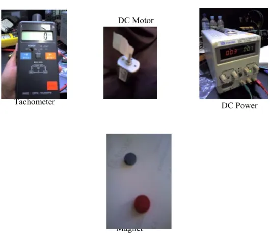
Procedure for testing of the DC Motor
Analysis of DC Motor Performance
A linear representation of each graph showing a linear increase in speed from zero for a given power input. For comparison, the linear representation of all three situations is placed on 1 axis, as shown in Figure 4.4. However, when we plot the graph using a scatter plot as shown in Figures 4.5 and 4.6, we can see that the motor rotates when the armature current is applied.
For example, as shown in Figure 4.6, for the DC motor with NdFeb magnets attached, it starts rotating at only 0.0447 watts without motor assistance. Meanwhile, the DC motor with bonded NdFeB magnets is able to rotate at low power with the help of starting.
Metallography Analysis
The NdFeB alloy powder with 5 wt% epoxy was observed under the optical microscope at 100x magnification and these are shown in Figure 2.7. The micrographs above show that the particles of the powder are tightly bonded together by epoxy. Until now, the pores were not visible due to the good distribution of the epoxy binder and the hardener.
The mixing process with acetone to dilute the resin and hardener also helps achieve a homogeneous mixture.
Magnetic Properties Analysis
Conclusion
Recommendation
This study can be added value if we can measure the torque of the motor, which by having the value can calculate the output power of the shaft. Pandian and B.D Pathak, Sintered NdFeB Magnet- Its potential in device application, Indo-ASEAN cost project DMRL Hydrabad. Idris Fabrication of pressureless fabricated polymer bonded NdFeB magnet and its magnetic and physical properties compared to compressed bonded magnet and ferrite magnet.
Davies, Composition and Microstructure-Dependent Spin Reorientation in Nanocrystalline (Nd-Pr)-(Fe-Co)-B Alloys, IEEEE [8] Bonded NdFeB Nanocomposite Permanent Magnet, M.H Saleh, M.I. To obtain the density of each sample, the weight and volume of the sample were determined. So the diameter and thickness must be measured to obtain the volume of the sample.
![Figure 2.1: Global production of magnet up to 2011 (In million US dollar)[15].](https://thumb-ap.123doks.com/thumbv2/azpdforg/10269534.0/14.918.285.697.97.388/figure-global-production-magnet-2011-million-dollar-15.webp)
![Figure 2.2: Sector wise demand of magnet in 2006 (in million US dollar)[15].](https://thumb-ap.123doks.com/thumbv2/azpdforg/10269534.0/14.918.278.705.720.959/figure-sector-wise-demand-magnet-2006-million-dollar.webp)