This is because the interstitial carbon atoms cause some of the iron BCC lattice cells to distort. According to Wikipedia (2009) sintering is the process where particles are heated in a controlled atmosphere furnace to a temperature below the melting point, but high enough to allow bonding (joining) of the individual particles. As the particles bond together, the strength will increase and all physical properties will also increase depending on the chemical composition of the particles.
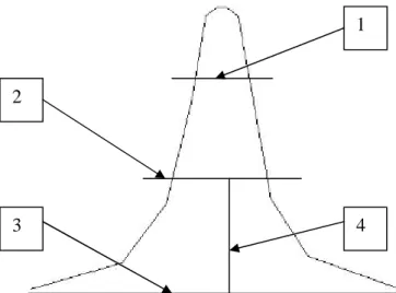
The pattern relies on the influence of a diffuse jet of material to compensate for the compression effect. The Vickers test can be used for all metals and has one of the widest ranges of hardness tests. This is one of the mechanical properties of this material and will determine whether or not the material is plausible for further study in the future.
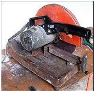
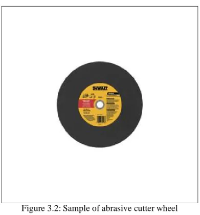
First, the steel bar is placed on the bed of the abrasive cutting machine. This action also ensures that the steel bar does not bounce off the machine when the abrasive wheel touches the surface of the steel.
SAMPLE TESTING PREPARATION
Although this step will also introduce some damage, we will minimize it by using a progressively finer sanding step. The author wants to make the sample's microstructure, especially on the surface, visible under the microscope.
SAMPLE EVALUATION METHODS
SAMPLE TESTING METHODS
GANTT CHART
RESULTS AND DISCUSSIONS
SAMPLE PRODUCTION
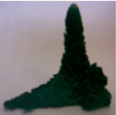
Because the author performs this method in open atmospheric conditions, the debris is exposed to oxidation during the advance flight from the abrasive wheel to the debris collector. Because all the debris is collected in one enclosed space, the heat cannot actually be released to the environment due to convective resistance.
SAMPLE TESTING PREPARATION
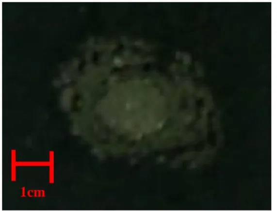
In the middle of the sample, the author can see that the surface is very smooth. But when we go to the edge of the pattern, the author can almost see some small lines. Then the author moves on to the third and fourth stages, which are grinding and polishing.
To remove saw marks and levels that may be found on the surface of the sample. At the end of this process, the author has successfully produced mirror finish of the sample. Before the author proceeds to the next stage, the sample is washed again with a stream of water followed by a stream of alcohol/ethanol.
This is to ensure that the surface is free of water and to prevent corrosion of the surface of the sample due to water being left on the surface. In this step, since the material is low carbon steel, the author uses nital solution.
MICROSCOPY INSPECTION 1
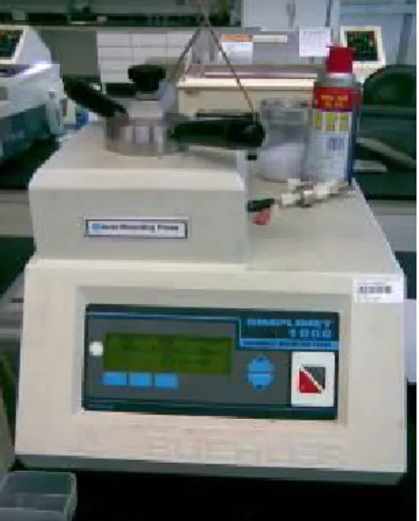
Then the author also washed it under liquid alcohol/ethanol to remove excess water from the surface and blew it with a hot air blower. These points are captured by DinoCapture, a new device in the materials laboratory for optical microscopy examination (Figure 4.9) and takes an image of the sample for examination. The author must ensure that the surface is completely level before examining the specimens under the microscope.
To do that, the author uses an additional editing section created specifically for this purpose. Between these two montages the author placed a small section of plasticine or dough mixture to sandwich between them. This pressing action ensures that the surface of the specimen is leveled accordingly.
Because of this, the project will later focus on the empty share in each point so that the author can tabulate the data first hand. This stuff may exist during sample preparation or perhaps some contaminants during sample cleanup.
MICROSCOPIC INSPECTION 2
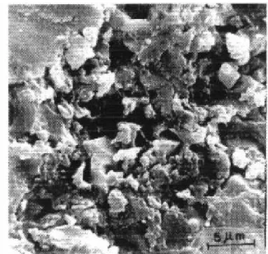
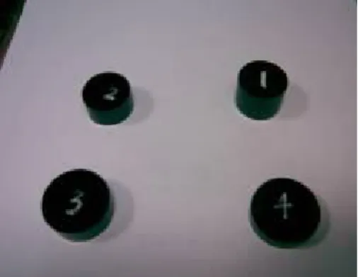
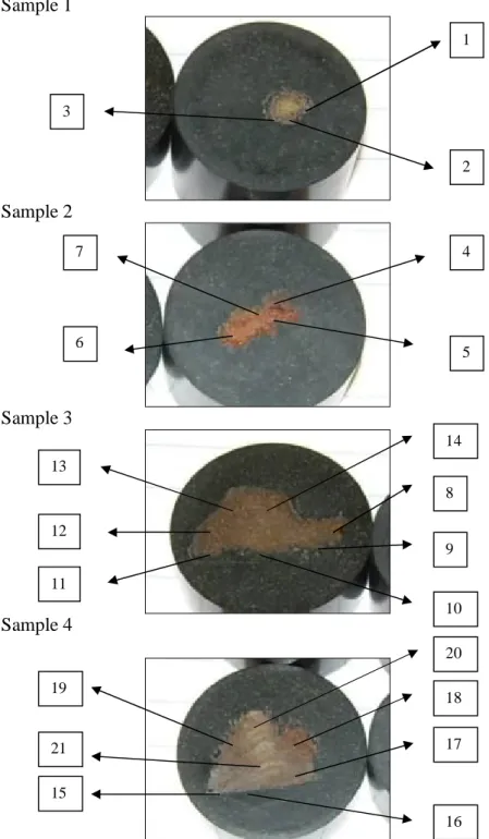
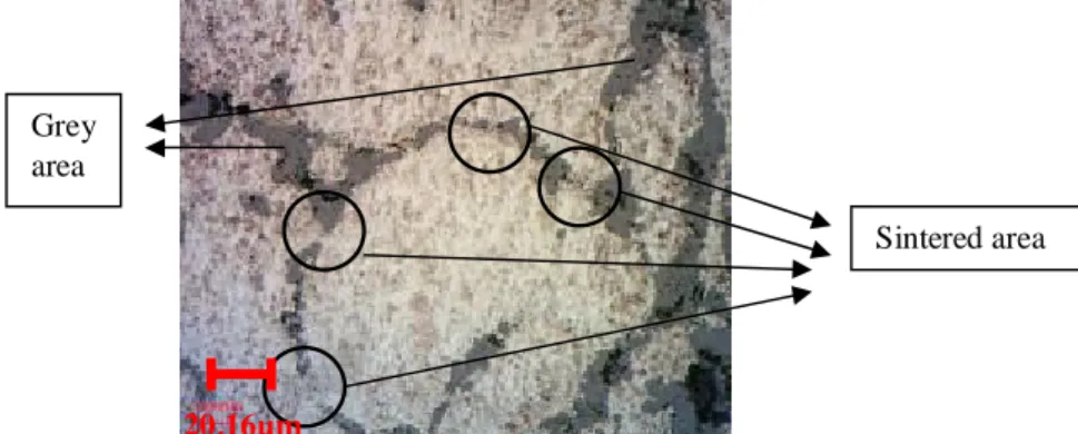
The black region is basically just a mounting material, so the author will not discuss it in this case. This area is mysterious to us because until now the author is still unable to determine the composition of the gray area. In this image, the author can see that the same phenomenon occurred in sample #2.
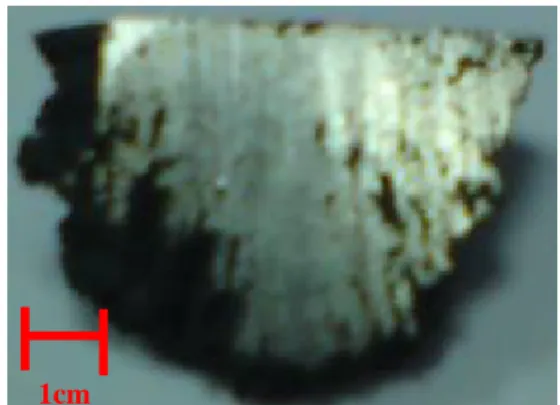
Because this is also the top view of the center section, the author cannot deduce how the particles stick together. But from here the author can say that the material seems to flatten out during impact. The author zooms in further to see the other interesting part of this point (see Figure 4.18).
In this sample, the author can clearly see that the particles have sintered together. If blackness is treated as void, then the author can say that there is less void in sample 3 compared to sample two. In this region, the damping effect is less because the particles are not loosely packed at the bottom.
From this point of interest, the author can see that the spray direction of the particle jet is close. If the author looks at all the points of interest in this sample, the author can see that every single point exhibits the same phenomenon. This is why the author can see the pattern of particles inside the specimen as above.
Here the author can clearly see that the particles are closely packed together. The area of sintering also increased to 10-15% of the total area, because the author is looking at the center part of the sample. To see the image clearly, the author has attached the sample image in Appendix IV for a better overview.
SCANNING ELECTRON MICROSCOPY AND X-RAY DIFFRACTION
HARDNESS TESTING
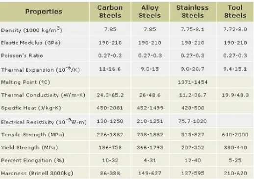
Here the maximum value of tensile strength is 908.2 MPa and the minimum value is 335.0 MPa. From this result the author can deduce that this material is actually within the practical tensile strength of steel, namely MPa. Hypothetically, the range of tensile strength may be due to the large differences in temperature distribution during jet sintering.
However, this value is only one of many characteristics to be studied regarding this material.
CONCLUSIONS AND RECOMMENDATIONS
CONCLUSIONS
RECOMMENDATIONS FOR FURTHER STUDY
It is good to have less oxidation because it forms a protective layer that can prevent the sintering process. If the technique is applied and proven, it will be a new discovery for the industry as an alternative to making aluminum foam.
GANTT CHART FOR FYP 1
GANTT CHART FOR FYP 2
ANALYSIS RESULT FROM SPECTROMETER
SAMPLE PICTURES TAKEN FROM OPTICAL MICROSCOPIC INSPECTION
RESULTS FOR HARDNESS TESTING