Target groups
Explanation of symbols used
Other documents
Feedback about these instructions
Product identification
Turck service
Turck assumes no responsibility for damages caused by failure to observe these warnings and safety instructions.
Intended use
Each IO-Link system consists of an IO-Link master and an IO-Link device (e.g. sensor, I/O hub, valve manifold). The system components are interconnected using standard 3-wire (Class A) or 5-wire (Class B) unshielded cables, depending on the port specification. The IO-Link technology is described in the "IO-Link interface and system specification" and IEC 61131-9.
The properties, functions and parameters of IO-Link devices are shown in the electronic device description (IODD). IODDs for Turck devices can be downloaded through the Turck Software Manager and are also available for free at www.turck.com. The IODD structure is defined by the IO-Link specification and is the same for all IO-Link devices.
In IODD, communication properties, device parameters, identification, process, diagnostic and device data are assigned fixed indices through which the parameters can be controlled.
Features
System architecture
Operating principle
Operating modes
IO-Link mode
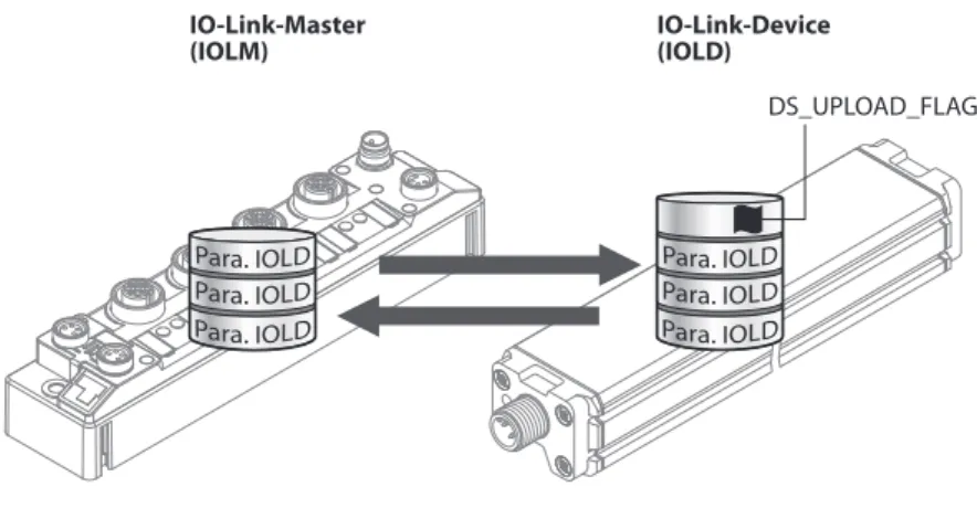
The data exchanged between the IO-Link master and the IO-Link device can be divided into cyclic process data and acyclic data. Data storage mode is only available for devices that comply with the IO-Link specification V1.1. Data storage mode allows IO-Link devices to be replaced without the need for reconfiguration.
The IO-Link master or IO-Link device retains the device parameters set in the previous configuration. In data storage mode, the parameter data memories of the IO-Link master and the IO-Link device are synchronized. If data storage mode is enabled on the IO-Link master, the master writes the saved device parameters to the new device after a device is replaced.
Standard I/O mode (SIO mode)
IO-Link configuration in PROFINET
IO-Link devices are connected to the ports of the IO-Link master unit via unshielded 3-core or 5-core standard cables. The IO-Link specification distinguishes between two types of ports with different power supplies for IO-Link master units. Class B IO-Link ports are suitable for connecting IO-Link devices with increased power consumption.
Wiring diagrams
IO-Link master
IO-Link device
Set the IO-Link master to IO-Link mode (see device-specific operating instructions). If the port is set to IO-Link mode, the IO-Link master attempts to establish communication with the IO-Link device. IO-Link communication is established in IO-Link mode by means of a wake-up request from the higher-level IO-Link master.
The IO-Link master first tries to establish transmission at the highest defined baud rate. If necessary, the parameters stored in the system are transferred from the IO-Link master to the device. IO-Link devices can be commissioned via a Turck IO-Link master in various types of controllers.
In PROFINET systems, the GSDML file of the IO-Link master is required for this purpose. In Ethernet/IP systems, the EDS file of the IO-Link master is required for this purpose.
Setting devices via a PC using a configuration tool
Setting using a USB adapter and configuration tool
Start the topology scan to find devices connected to the IO-Link adapter: Right-click the IO-Link adapter Ò Click Topology Scan. Select the IODD for the connected device if the device is not detected automatically (see red mark). Establish a connection between the IO-Link device and the PC by right-clicking on the device.
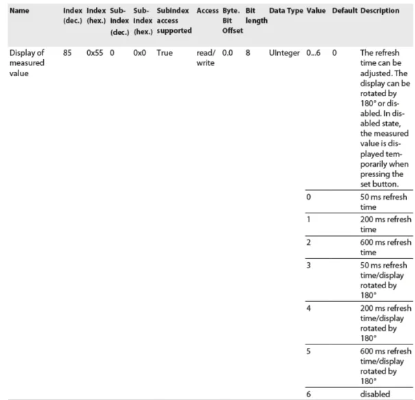
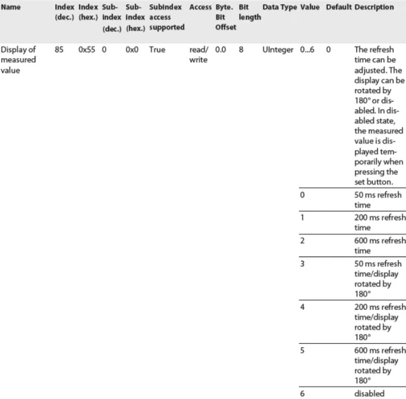
Adjustable parameters can be found in the IO-Link device-specific parameter manuals or in IODDfinder. The parameter manuals contain a description of the IODD and are available for download at www.turck.com. Example: The command "Rotate the screen and set the measured value update time" is controlled through index 85.

Setting with IO-Link master and configuration tool
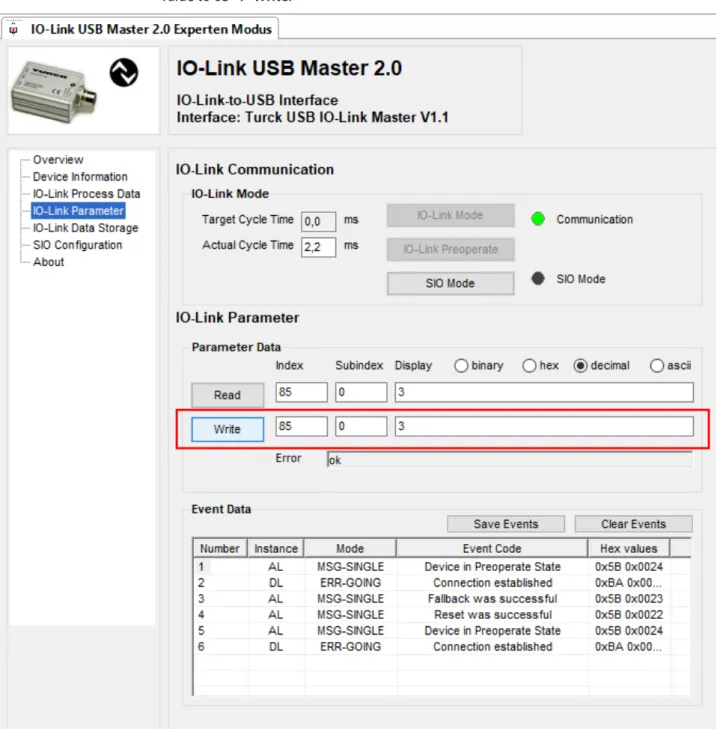
The information icon can be used to query the respective firmware version of the port and the IO-Link master. Start the topology scan to find devices connected to the IO-Link adapter: right-click on IO-Link USB Master 2.0 Ò Topology Scan. If the topology scan finds a DTM instead of an IODD, load IODD manually: right-click on device Ò Swap Device.
Connect the host PC and the IO-Link device by right-clicking on the IO-Link device Ò. Set the parameter Display of measured value in the drop-down menu to 50 ms update time/display rotation 180°.
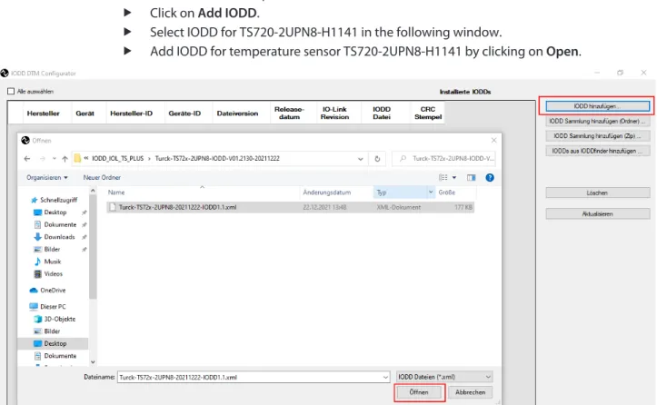
Set with IO-Link master and IODD configurator
Enter the password in the Login field on the home page of the web server.
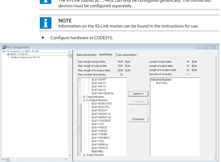
Configuring devices using the control program
Commissioning with BL… and programmable gateway in CODESYS 2
In online mode, process data can be read out if an IO-Link device is connected.
Commissioning with BL… and TX500 in CODESYS 3
Commissioning with TBEN and TX507 in CODESYS 3
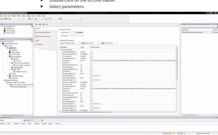
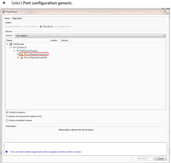
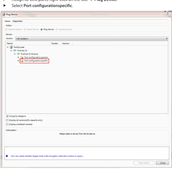
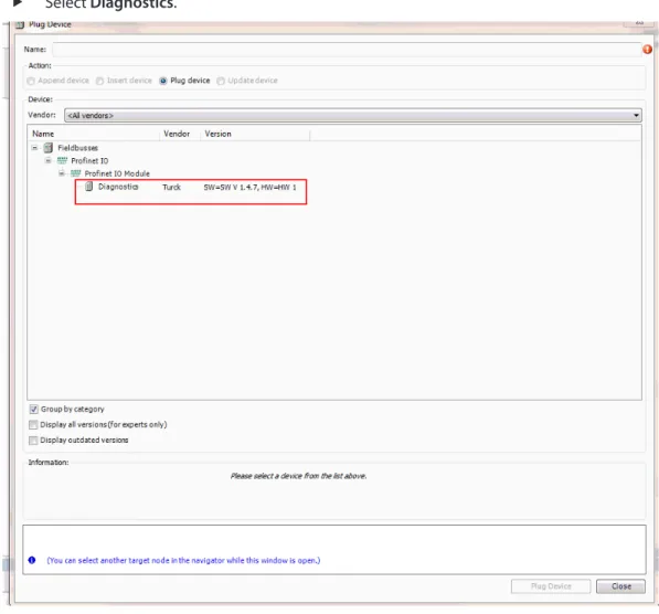
TBEN IO-Link master slot assignment: right-click on the slot Ò Select Plug Device…. With a special configuration, IO-Link devices can be individually set in addition to the parameters of the IO-Link master. When the application is started in the controller, the settings are transferred to the device via PROFINET.
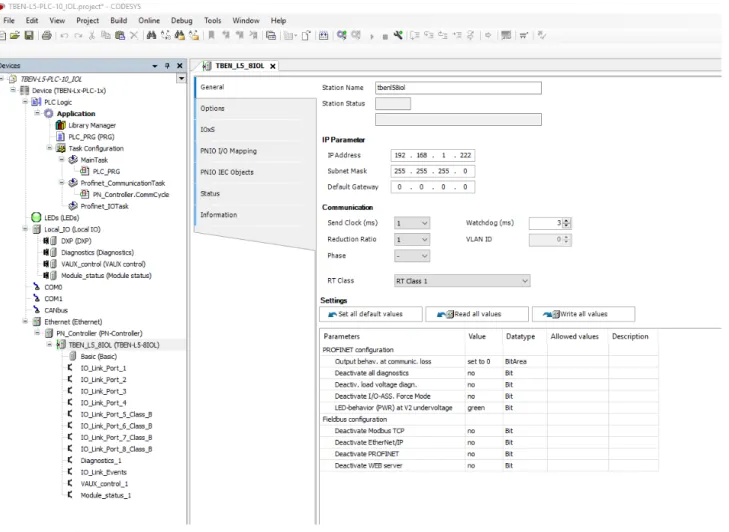
Commissioning with TBEN-L…-8IOL and TBEN-L5-PLC-1… in CODESYS 3
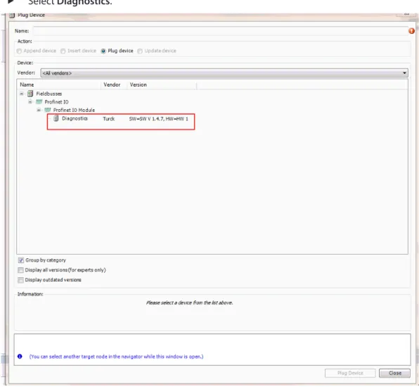
The last four slots are intended for diagnostics, IO-Link events, VAUX Control and module status.
Commissioning with BL… and Siemens controller in Simatic Manager (V5.5)
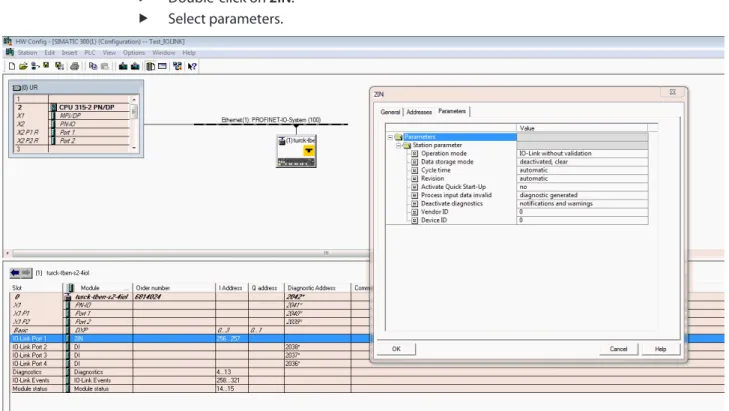
Commissioning with TBEN and Siemens controller in Simatic Manager (V5.5)
The GSDML file for TBEN devices can be used to set the parameters for IO-Link devices.
Commissioning with BL… and Siemens controller in the TIA Portal V13 SP1
Process values can be monitored in online mode if an IO-Link device is connected.
Commissioning with TBEN and Siemens controller in the TIA Portal
Commissioning with TBEN-L…-8IOL and Siemens controller in TIA Portal V16
The number of input words and output words of the IO-Link device can be found in the datasheet, the IO-Link parameter manual or the IODDfinder.
Commissioning with TBEN and Allen-Bradley controller in Rockwell
Setting devices using the control program with the function block
Setting with programmable gateway and CODESYS 3
The function block is found in the library for programmable gates BLxx_PG_PB.lib. The library is part of the targeted support package for BLxx-PG-EN and is available free of charge at www.turck.com. For information on configuring the IO-Link master with CODESYS, refer to the device-specific instructions for use.
The required parameter values for configuring an IO-Link device can be found in the IODD finder or in the IO-Link parameter manual for the individual device. The required IO-Link device parameter values can be found in IODDfinder or in the IO-Link parameter manual for the individual device. Enter a value of 5 in the Array WRITE field to rotate the display 180° and set the measured value update time to 200ms.
Setting with programmable gateway and CODESYS 2
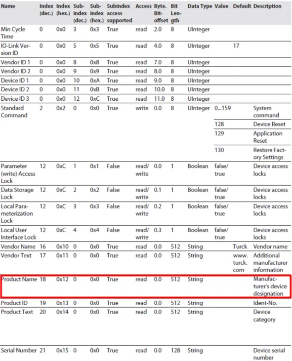
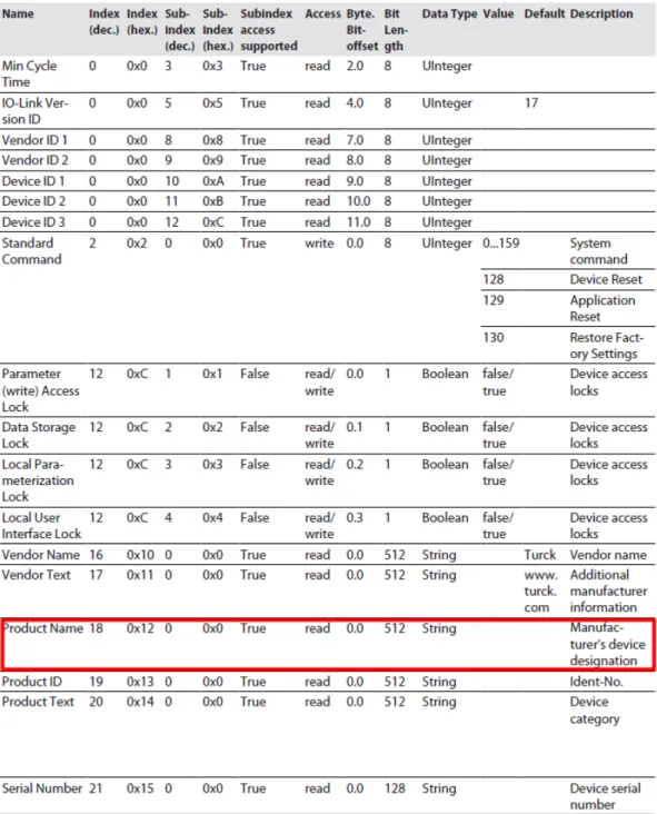
130: Excerpt from the parameter manual for the IO-Link I/O hub TBIL-M1-16DIP (example: read out product names).
Setting with Siemens S7-1200 or S7-1500 Controller and TIA Portal
Setting with Siemens S7-300/400 and STEP7 V5.5 Controllers
Enter the value 5 to be written in the variable table under Control value to rotate the display 180° and set the measured value update time to 200ms. If no settings are required on the IO-Link device, the signals are forwarded directly to the higher-level control system. For more information on the operation of IO-Link masters and IO-Link devices, refer to the device-specific instructions for use.