This operating manual describes the structure, functions and use of the product and helps you operate the product as intended. For all general information about the BL20 and BL67 IO systems, please read the manuals for the product families (see Additional documents (page 6)). These instructions are intended for qualified personnel and must be read carefully by anyone who installs, commissions, operates, maintains, disassembles or disposes of the device.
The notes make work easier, provide more information about specific actions and help avoid overtime due to not following the correct procedure. We make every effort to ensure that these instructions are as informative and clear as possible. If you have suggestions to improve the design or if information is missing from the document, please send your suggestions to [email protected].
You can access the product database at the following address: www.turck.de/produkte. Turck accepts no liability for damages caused by failure to observe these warning and safety notices.
Intended Use
General Safety Instructions
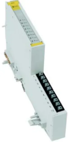
The Turck IO-Link BL20-E-4IOL(-10) or BL67-4IOL main modules are technological modules of the BL20 and BL67 modular I/O systems. They can be connected to several fieldbus systems and Ethernet protocols via appropriate gateways. The four IO-Link channels can be parameterized independently and can optionally be operated in IO-Link mode (IOL) or in standard I/O mode (DI mode).
The four universal digital channels are designed as XSG channels and can therefore be parameterized as input or output.
Device Overview
Properties and Features
Compatible gateways
Compatible BL20 gateways
Compatible BL20 gateways, CODESSYS programmable
Compatible BL67 gateways
Compatible BL67 gateways, CODESYS programmable
Technical data
Connecting
BL67-wiring diagram
BL20-wiring diagram
The IO-Link devices must be supplied with the same potential as UL of the port or the BR/PF module (if used).
Process image
Process input data
Process output data
Process Data Mapping
Parameters
Parameters for BL20-E-4IOL and BL67-4IOL
The IO-Link master starts the port in IO-link mode, parameterizes the device and sets the port back to DI mode. The port remains in DI mode until a new IO-Link request is sent from the higher-level controller. Synchronization of parameter data of IO-Link devices (saving the parameters of the connected device in the master).
For fast applications (e.g. utility-changing applications), the start-up time of IO-Link devices can be shortened. The start time defined in the IO-Link specification (TSD = Device Detection Time) is reduced. It may therefore be necessary to check whether the used IO-Link device starts in this mode.
01 Notifications The master sends all IO-Link events to the fieldbus except IO-Link messages. The master sends all IO-Link events to the fieldbus except IO-Link messages and warnings.
Parameters for BL20-E-4IOL-10
The master checks whether the device type (Vendor ID and Device ID) of the connected device matches the device type of the configured one. If the master detects a mismatch, IO-Link communication is established, but there is no process data exchange. The master checks whether the device type (Vendor ID and Device ID) and serial number of the connected device match the data of the configured one.
If the master unit detects a mismatch, IO-Link communication is established, but no process data is exchanged. 11 24 VDC Output switches to 24 VDC and provides sensor power for the IO-Link port. Depending on the parameterization, the master unit transmits events based on their priority to the fieldbus or not.
Defines the length of the process input data assigned to the fieldbus for this port. Defines the length of the process output data assigned to the fieldbus for this port.
Special DTM functions
Diagnostic and status messages
LED displays
No input data received from the connected device (applies only to devices with input data length . > 0),. The connected device does not respond to sending output data (only applies to devices with output data length > 0).
Diagnostic data
Check the status of the IO-Link index "Device Access Locks" (index 0×C) on the connected device and unlock the device. The connected device is not in the "operate" state, which means that it is not ready for operation. The connected device does not match the configured Additional diagnostic message Wrong or missing device (Seite 33).
Certain IO-Link devices send a "process input data invalid" diagnosis if the process value cannot be measured. For the exact specification of the device diagnostics, please read the device documentation for the device. The process value is below the parameterized measuring range, or the selected measuring range is selected too high.
The process value exceeds the parameterized measuring range or the selected measuring range is selected too low. The device sends an error (device status 4, according to the IO-Link specification), which is not clearly specified. Read the event codes of the device so that you can specify the error more precisely.
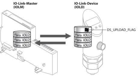
The principle of the data storage mechanism
- General
- Parameters: Data storage mode = activated
- Parameters: Data storage mode = read in
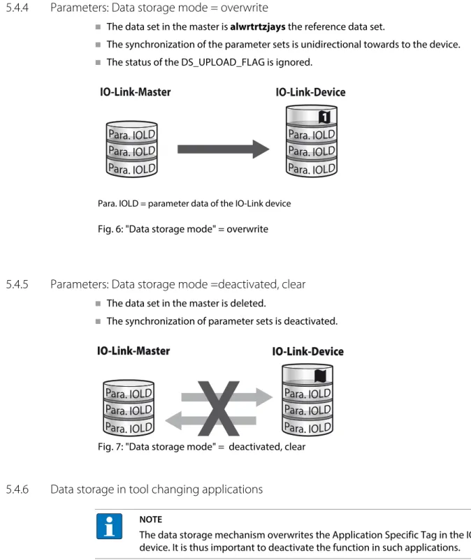
- Parameters: Data storage mode = overwrite
- Parameters: Data storage mode =deactivated, clear
- Data storage in tool changing applications
A defective device is replaced by a device with a previously changed parameter set (e.g. via DTM). An IO-Link exchange device with unknown parameter data must be reset to factory settings before being connected to the master. This prevents unknown device parameter settings from being downloaded to the master when the connection is established.
TURCK IO-Link devices can be reset to factory settings via a system command using a generic IO-Link-DTM and device-specific IODD.
Functions for the acyclic communication via IO-Link CALL
Port functions for port 0 (IO-Link master) IO-Link-Index (Port function invocation)
Master Port Validation Configuration
IO-Link Events
Warning, Notification, Single shot event, etc.) in accordance with IO-Link specification "IO-Link Interface and System".
Set Default Parameterization
Teach Mode
Master Port Scan Configuration
Extended Port Diagnostics
General
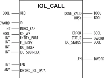
The IO-Link IOL_CALL function block is specified in the IO-Link specification "IO-Link Integration Part 1 - Technical Specification for PROFIBUS and PROFINET".
IOL_CALL in accordance with IO-Link specification
IOL_CALL
Turck IO-Link Function Blocks
- IO-Link CALL (Turck) Input variables
- STATUS - communication error status
- IOL_STATUS
The function block is supported by all Turck IO-Link masters with mutiprotocol functionality. The use of the function block for third-party IO-Link masters is also possible, provided that the devices comply with the PNO or PI specification. Ethernet protocol used and varies depending on the module used, see Address assignment of the IO-Link master module (page 49).
PROFINET ID DWORD ID of the PROFINET slave The ID can be read with the "GetID". Slot USINT Slot number of the IO-Link module in the BLxx station Modbus TCP Slot USINT Slot number of the IO-Link module in the BLxx station. Length of data to be written cannot be handled from the module, possibly wrong module accessed 0×xx80B2xx ACCESS_INVALID_.
0×xx80C2xx RESOURCE_BUSY The IO-Link master module is busy or waiting for a response from the connected IO-Link device. Possible cause: the addressed port is parameterized as DI and is not in IO-Link mode. 0×8021 SERV_NOTAVAIL_LOCCTRL The service is temporarily unavailable, the device is busy (eg teaching or parameterizing the device on the active device).
0×8033 VAL_LENOVRRUN Length of data to be written does not match the length defined for this parameter.
Example project
- Used Hardware
- Used Software
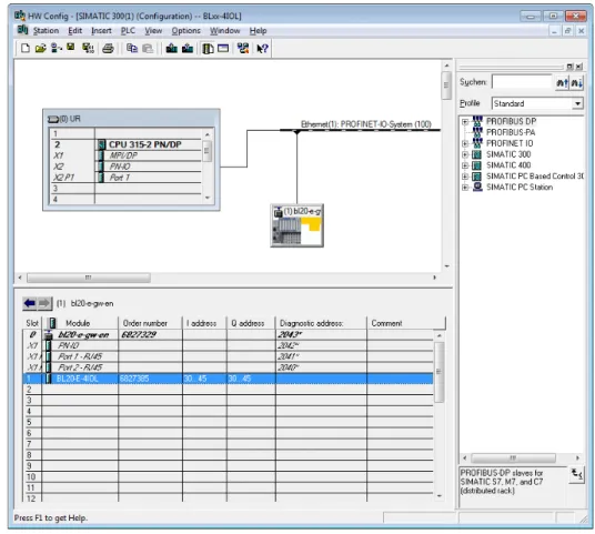
Configuration
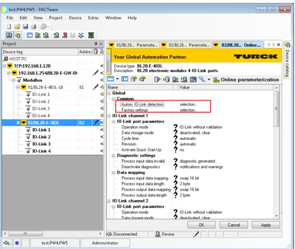
- Configuration of the IO-Link master
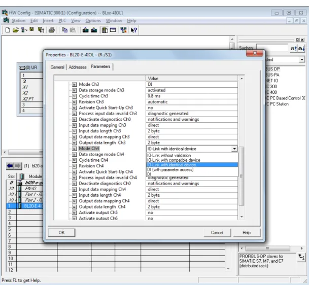
- Configuration of the IO-Link ports
In "Process input data length" and "Process output data length" enter the length of the process data of the connected device to be mapped to the field bus for this port, see also Parameters, p. It makes sense to set "process input data length" and "process output data length" to 0 so as not to block digital data bytes when mapping process data to the fieldbus. IO-Link with identical device In the event of a device exchange, only an identical device is accepted for exchange (check vendor ID, device ID, etc., see also Parameters (Page 20).
IO-Link without validation Any IO-Link device is accepted as an exchange device in case of a device exchange Parameters (page 20).
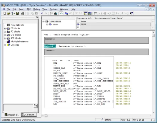
Usage of the function block in Step 7
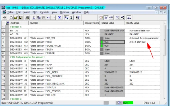
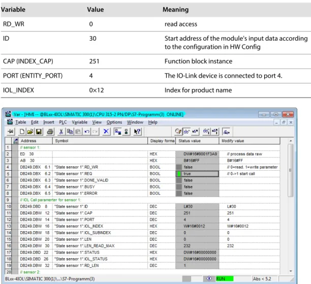
- Example accesses with IOL_CALL
In this example, the variable table "HMI" serves to visualize the procedure of read and write access via IOL_CALL. You can find the assignment of the SPDU indexes of IO-Link devices in the respective device documentation. Read out the product name (product name, index 0x12) of the Turck IO-Link I/O hub TBIL-M1-16DIP on IO-Link port 4.
Example project
- Used Hardware
- Used Software
Hardware configuration
- Configuration of the IO-Link master
- Configuration of the IO-Link ports
IO-Link without validation Every IO-Link device will be accepted as exchange device in case of a device exchange, see also Parameters (page 20).
Use the IO_LINK_DEVICE function block in TIA Portal
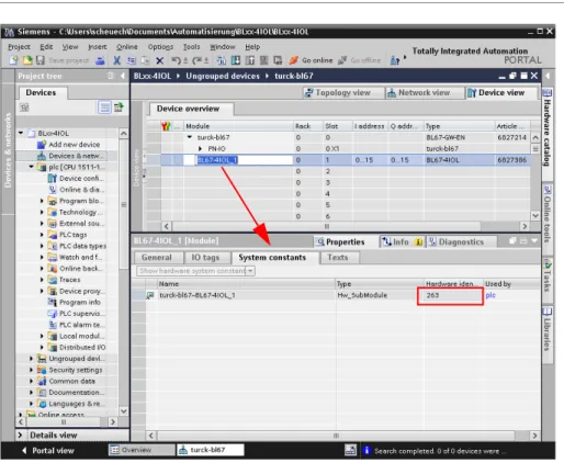
- Example accesses with IO_LINK_DEVICE
In this example, the "Sensor1" clock table serves to visualize the read and write access procedure via IO_LINK_DEVICE. The function block accesses the connected device and sensors via the input variable "ID". IO-Link module hardware identifier, as in example (with CPU 1511-PN) - IO-Link module input data start address (e.g. on a CPU 315).
Example project
Configuration in CODESYS
- Prerequisites
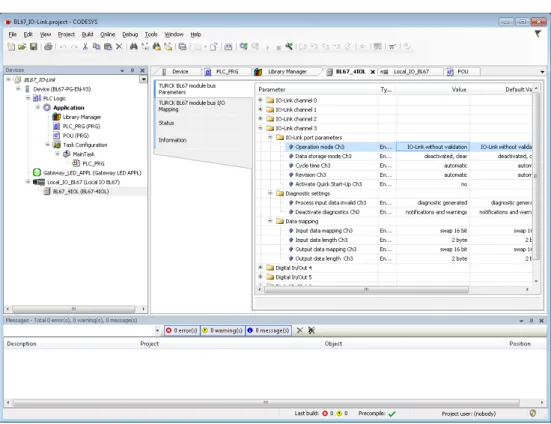
- Configuration of the IO-Link ports
IO-Link with identical device Only an identical exchange device is accepted in a device exchange (verification of vendor ID, device ID, etc., see Parameters (page 20). IO-Link without validation Each IO-Link device is accepted as an exchange device in case of a device exchange, see Parameters (page 20).
Usage of the function block in CODESYS
You can find the assignment of the subindexes of IO-Link devices in the respective device documentation. Read out the product name (product name, index 0x18) of the Turck IO-Link I/O hub TBIL-M1-16DIP on IO-Link port 1.
Start-up: IO-Link-Device with IO-Link V1.0
Start-up: IO-Link-Device with IO-Link V1.1
Start-up problems - frequently failure causes