USER MANUAL INCLINoMEtERS WItH CANoPEN®- INtERFACE
B2N10H-Q42-CNX2-2H1150 B2N45H-Q42-CNX2-2H1150 B2N60H-Q42-CNX2-2H1150
Sense it! Connect it! Bus it! Solve it!
All brand and product names are trademarks or registered trade marks of the owner concerned.
D101846 1801 - Inclinometers 0-1
0 About this manual
0.1 Documentation concept...2
0.1.1 Explanations of the used symbols... 2
0.2 General information ...3
0.2.1 Intended use ... 3
0.2.2 Information for project planning/ installation of product ... 3
About this manual
0.1 Documentation concept
The first chapter of this manual contains an overview of the TURCK Inclinometers.
The second chapter contains all technical data.
The third and fourth chapters contain information for mounting and the electrical connection.
The fifth chapter contains information for the CANopen interface.
The glossary contains explanations for various CANopen-specific terms.
0.1.1 Explanations for the used symbols
Danger
This symbol is positioned next to warnings which point to a source of danger. This may refer to injury to persons and to damage to systems (hard- and software).
For the user this symbol means: Please proceed with special care.
Attention
This symbol is positioned next to warnings which point to a potential source of danger.
This may refer to possible injury to persons and to damage to systems (hard- and software) and installations.
Note
This symbol is positioned next to general instructions which point to important information prior to proceeding step by step.
The respective instructions may lighten the work and, for example, may help prevent extra work caused by the wrong course of action.
D101846 1801 - Inclinometers 0-3 General information
0.2 General information
Attention
It is strongly recommended you read this section because safety in connection with handling electrical devices may not be left to chance.
This manual contains the required information for the start-up of the TURCK Inclinometers.
It was written specifically for qualified staff with the required technical know-how.
0.2.1 Intended use
Danger
The devices described in this manual may only be used for the intended applications also found in this manual and in the respective technical description, and only in connection with certified OEM devices and OEM components.
The flawless and safe operation of the devices is based on the appropriate transport, storage, assembly, and mounting, as well as careful operation and maintenance.
0.2.2 Information for project planning/ installation of product
Danger
The valid safety and accident prevention rules for the respective application must be adhered to.
About this manual
D101846 1801 - Inclinometers 1-1
1 Overview
Overview
1.1 Characteristics
The biaxial inclinometers are suitable for measuring inclinations within the ranges ±10°, ±45° and
±60°. The zero point and measurement range end values are factory calibrated at 25 °C to guarantee high accuracy.
The compact and robust design transforms the sensor into a suitable angle measurement device in a harsh environment and for diverse industrial and automotive engineering applications. The standardized CANopen interface allows user-friendly configuration and start-up. All parameters are stored in a non-volatile memory buffer.
TURCK offers the following sensors:
Table1:
Sensor types
Type Inclination range
B2N10H-Q42-CNX2-2H1150 ±10°
B2N10H-Q42-CNX2-2H1150 ±45°
B2N60H-Q42-CNX2-2H1150 ±60°
Special characteristics:
Biaxial inclinometers with measurement ranges: ±10° / ±45° / ±60° (depending on design)
High resolution and accuracy
User-friendly CANopen interface:
– meets CiA DS-301, device profile CiA DSP-410 – Baud rate of 10 kBit/s to 1 MBit/s
High sample rate and bandwidth
Parameterizable vibration suppression
Functions:
– one TPDO (RTR, cyclic, event-driven, synchronized)
– SYNC Consumer (synchronized sending of TPDO after receipt of SYNC telegram) – EMCY Producer (limit value exceedance, device internal temperature check) – failure check with the help of Heartbeat or Nodeguarding / Lifeguarding – freely configurable limit frequency (digital filter)
Robust plastic housing
Suitable for industrial applications:
– temperature range: -40 °C to +80 °C – housing protection class: IP68/69K
D101846 1801 - Inclinometers 1-3 Applications
1.2 Applications
The inclinometers are based on MEMS technology (micro-electrical-mechanical systems) and offer diverse application solutions:
Machines and vending machines
Vehicles and airplanes
Harvesters, agricultural machines and construction vehicles
Transportation devices
Overview
D101846 1801 - Inclinometers 2-1
2 Technical data
Technical data
2.1 General, interface, electrical and Table 1:
General para- meters
General parameters
Measurement axes 2 (X/Y)
Measurement ranges ±10° / ±45° / ± 60°
Resolution 0,05° / 0,1° / 0,1°
Calibration accuracy (at 25 °C) ±0. 1° (zero point and end values)
Non-linearity max. ±0.2° / ±0.3° /±0.4°
Temperature coefficient (zero point) Type ±0.008°/K
Limit frequency Type 20 Hz, 2nd order (no digital filter) / 0.3...25 Hz, 8th order (with digital filter)
Sample rate 100 Hz
Operating temperature -40...+80 °C
mechanical parameters
Table 2:
Interface characteris- tics
Interface characteristics
Interface CANopen, per CiA DS 301,
profile per CiA DSP-410
Bit rate 10 kbps, 20 kbps, 50 kbps, 250 kbps,
500 kbps, 800 kbps, 1 Mbps
Functions TPDO (RTR, cyclic, event-driven,
synchronized), parameterization per SDO and object register, digital filter (Butterworth Lowpass, 8th order), SYNC Consumer, EMCY Producer, output and control of internal device temperature (±2.0 K accuracy), failure control with the help of Heartbeat or Nodeguarding / Lifeguarding
Table 3:
Electrical parameters
Electrical parameters
Power supply voltage 10...30 VDC (The inclinometer must be supplied with the help of a car battery or a safety-low voltage (SELV) with limited power.)
Current consumption 40...105 mA
Table 4:
Mechanical parameters
Mechanical parameters
Connection CAN Sensor connector assembly M12, 5-pole
Housing protection class IP68/69K
Shock resistance max. 30 g (11 ms)
Weight approx. 160 g
D101846 1801 - Inclinometers 2-3
General, interface, electrical and mechanical parameters
Technical data
D101846 1801 - Inclinometers 3-1
3 Mounting
Mounting
3.1 Dimensional drawing Figure 1:
Dimensional drawing
42,5 22,85 42,5
67,7 M12 x 1
52
ø 5,3 LED
2 M12 x 1
3.1.1 Figure 2:
Axes- Definition
+y
y x
+x
Definition of the axes (factory default)
D101846 1801 - Inclinometers 4-1
4 Electrical connection
4.2
Electrical connection
4.1 Pin assignment of connector assembly
The inclinometers are equipped with a 5-pole round connector M12 (A-coded).
The pin assignment meets CiA DR-303-1 (Diagram 1 and Table 1).
Figure 1:
M12 connector assembly
5 CAN_L 4 CAN_H 1 shield 3
2 +
Table 1:
Pin assignment
Pin Signal Assignment
1 CAN_SHLD Shield
2 CAN_V+ Supply voltage (+24 VDC)*
3 CAN_GND GND
4 CAN_H CAN_H-bus line
5 CAN_L CAN_L-bus line
*) UL marking requires an approved power supply with energy limitation (UL 61010-1) or with Class 2 according to National Electric Code (USA) / Canadian Electric Code.
D101846 1801 - Inclinometers 4-3 Bus termination resistance
4.2 Bus termination resistance
The inclinometers are not equipped with an internal termination resistance.
If needed, it is to be realized externally with the help of a T piece at the end of the bus (120 ò).
Electrical connection
D101846 1801 - Inclinometers 5-1
5 CANopen interface
5.1 Review of functions ...2
CANopen interface
5.1 Review of functions
The inclinometers are equipped with a standardized CANopen interface per CiA DS-301 and a device profile per CiA DSP-410. All measured values and parameters are accessible via the object register (OR). The individual configuration can be stored in the internal, non-volatile memory buffer (EEPROM).
The following CANopen functions are available:
one Send Data object (TPDO1) with four possible operating modes:
– individual request per Remote Transmit Request telegram (RTR) – cyclic Send per interval time
– event-driven Send when angle has changed – synchronized Send after receipt of SYNC telegram
one Service Data object (Standard SDO)
error messages per emergency object (EMCY) with the help of:
– the general error register
– the manufacturer specific status register (Manufacturer Status) – the error list (Predefined Error Field)
monitoring mechanism Heartbeat, as well as Nodeguarding/ Lifeguarding
storage and reload function of all parameters (Store and Load Parameter Field)
status and error display per two-color LED (per CiA DR-303-3)
Next to the CiA DS-301 functionality, additional manufacturer or rather profile specific characteristics exist:
setting of Node ID, as well as Baud rate per OR
freely configurable limit frequency (digital filter)
configuration of minimal change of angle for TPDO1 send event
optional monitoring of internal device temperature
direction switch of inclinometers
D101846 1801 - Inclinometers 5-3 Send PDO (TPDO1)
5.2 Send PDO (TPDO1)
Each inclinometer has exactly one Send Process Data Object (TPDO). It contains the current inclination values (longitudinal and lateral), as well as the internal device temperature.
PDO mapping of measurement values is fixed as displayed in Table 1.
Table 1:
PDO mapping of TPDO1
Data portion of CAN telegram of the TPDO1
Byte 0 Byte 1 Byte 2 Byte 3 Byte 4 Byte 5 Byte 6 Byte 7 Inclination value
longitudinal (X-axis), OR: 6010 h
Inclination value lateral (Y-axis), OR: 6020 h
Internal tempera ture, OR:
5000 h
Not used
CANopen interface
5.3 PDO communication types
5.3.1 Individual request per Remote Transmit Request telegram (RTR)
A request can be sent to TPDO1 anytime by sending a Remote Transmit Request telegram. This is possible in all operating modes of the inclinometer.
5.3.2 Cyclic operating mode
Cyclic sending of TPDO1 is activated if the entry 1800h/05h (interval time in milliseconds) contains a value greater than 0. For this purpose the entry 1800h/02h (transmission type) must contain the value 254 (asynchronous, manufacturer specific). In the "Operational" mode, the inclinometer cyclically sends the TPDO1 with the set cycle duration time.
5.3.3 Event-driven Send when the angle has changed
The bus load caused by PDOs can be decreased by only sending the TPDO1 when the angle has changed accordingly. This function can be configured under the index 3001h in the manufacturer specific portion of the object register. For this purpose the entry 1800h/02h (transmission type) must contain the value 254 (asynchronous, manufacturer specific).
5.3.4 Synchronized Send after receipt of a SYNC telegram
For the synchronized transmission, the SYNC object is made available by CANopen; here, the TPDO1 is sent after each "nth" receipt of a SYNC telegram. For this purpose the entry 1800h/
02h (transmission type) must contain the value n=1...240.
D101846 1801 - Inclinometers 5-5 Object register
5.4 Object register
The object register of the inclinometers is divided into three parts (communication parameters, manufacturer specific portion, profile specific portion). The existing parameters can be read and written via the Standard SDO and index/subindex. Parameter changes become immediately valid with the exception of the Node ID (2000h) and the Baud rate (2001h).
The following paragraphs provide a description of all parameters in the object register of an inclinometer including index, subindex, data type, access rights and standard value
(manufacturer default setting). The column Store identifies whether a parameter can be stored in the internal, non-volatile memory buffer (write "save" signature in OR index 1010h/01h).
5.4.1 Communication parameters (per CiA DS-301) Table 2:
Communicati on parameter in the object register
Index Sub- index
Parameter Data type
Access Standard value
Store
1000h 0 Device type (device profile 410, two axes)
UNS32 const 2019Ah
1001h 0 Error register UNS8 ro 0
1002h 0 Manufacturer status register UNS32 ro 0 1003h Predefined error field
0 Number of error entries UNS32 rw 0
1...5 Error code (oldest error in highest index)
UNS32 ro 0
1005h 0 COB ID SYNC message UNS32 rw 80h
100Ah 0 Software version ("xyy") VSTR const typical 100Ch 0 Guard Time (a multiple of
1 ms)
UNS16 rw 0 x
100Dh 0 Lifetime factor UNS8 rw 0 x
1010h Store parameters
0 Highest supported subindex UNS32 ro 1 1 Store all parameters
(signature: "save" - 65766173h)
UNS32 rw 0
1011h Reload manufacturer default setting UNS32
0 Highest supported subindex UNS32 ro 1 1 Reload all manufacturer
default settings (signature:
"load" - 64616F6Ch)
UNS32 rw 0
1014h 0 COB ID emergency message
UNS32 ro 80h+NID
CANopen interface
1015h 0 Off-time between two EMCY messages (a multiple of 100 µs)
UNS16 rw 0 x
1017h 0 Heartbeat interval time (a multiple of 1 ms, 0 deactivated)
UNS16 rw 0 x
1018h Identity object
0 Highest supported subindex UNS8 ro 4
1 Vendor ID UNS32 ro 159h
2 Product code UNS32 ro typical
3 Revision No. UNS32 ro typical
4 Serial No. UNS32 ro typical
1200h Server SDO1 parameter
0 Highest supported subindex UNS8 ro 2
1 COB ID Client > Server UNS32 ro 600h+NID 2 COB ID Server > Client UNS32 ro 580h+NID 1800h Transmit PDO1 communication
parameters
0 Highest supported subindex UNS8 ro 5
1 COB ID UNS32 ro 180h+NID
2 Transmission type (synchronous/
asynchronous manufacturer specific)
UNS8 rw FEh x
3 Off-time between two TPDO messages
(a multiple of 100 µs)
UNS16 rw 0
Table 2:
Communicati on parameter in the object register
Index Sub- index
Parameter Data type
Access Standard value
Store
D101846 1801 - Inclinometers 5-7 Object register
1 Inclination value longitudinal (X-axis, hundredfold angle value in °)
UNS32 ro 60100010
h 2 Inclination value lateral (Y-
axis, hundredfold angle value in °)
UNS32 ro 60200010
h
3 Internal temperature (in °C) UNS32 ro 50000008 h
Table 2:
Communicati on parameter in the object register
Index Sub- index
Parameter Data type
Access Standard value
Store
CANopen interface
Error register (1001h)
The error register displays the general error status of the device. Each bit represents an error group. If a Bit is set (=1), at least one error of this group remains active at this time.
The content of this register is transmitted in each EMCY message.
The following error groups may occur:
Table 3:
Error register (1001h)
Error register (1001h)
Bit 7...Bit 6 Bit 5 Bit 4 Bit 3 Bit 2...Bit 1 Bit 0
Not used Profile
specific error
Not used
Temper ature error
Not used At least
one error active If the device remains in the error status (at least one error active), it is displayed by set Bit 0.
During active monitoring of the internal device temperature (5001h/01h = 1), Bit 3 is set when set limit values (5001h/02h...03h) have been underreached or rather overreached.
A profile specific error (sensor error) is displayed by Bit 5.
Manufacturer status register (1002h)
This register displays the current status of all detectable errors. Each bit represents a specific error. If a Bit is set (=1), thus this error is currently active. The low-order 16 bit of this register (Bit 15... Bit 0) are sent in each EMCY message in the first two byte of the manufacturer specific portion and also entered into the additional information field (bit 31... bit 16) of the predefined error field 1003h.
The following errors may occur:
Table 4:
Manufacturer status register (1002h)
Manufacturer status register (1002h)
Bit 31 ...
Bit 9
Bit 8 Bit 7 ...
Bit 6
Bit 5 Bit 4 Bit 3 ...
Bit 2
Bit 1 Bit 0 Not
used
EEPRO MError
Not used
Temper ature overreac h
Temper ature underre ach
Not used
Lateral sensor error
Longitu dinal sensor error
D101846 1801 - Inclinometers 5-9 Object register
The EEPROMError Bit (Bit 8) displays a significant hardware error. This bit is set when erroneous data is read from the EEPROM during storing or rather reloading device parameters (1010h/01h and 1011h/01h) or after power-on of an inclinometer.
Predefined error field (1003h)
Each inclinometer compiles an error list concerning the five errors that have occurred last. The entry 1003h/00h contains the number of error entries in the error field. All other subindices contain all occurred error states in chronological sequence; the error that has occurred last may always be found under subindex 01h. The oldest error may be found in the highest subindex (value of 1003h/00h) available and is removed first from the list when more than five errors have occurred. If an error occurs, a new error entry is added to 1003h and an EMCY message is sent as well.
An erorr entry is structured as follows:
Table 5:
Error entry in the
predefined error field (1003h)
Error entry in the predefined error field (1003h)
Additional information field (bit 31...bit 16) Error code (bit 15...bit 0) bit 15...bit 0 of the manufacturer status
register 1002h (at the time the error has occurred)
4200h (temperature error), 5000h (hardware error), FF00h (device specific error) The error list may be completely deleted by writing 0 into the entry 1003h/00h.
Store parameters (1010h) and reload (1011h)
If parameters are changed in the OR, the changes become immediately valid with the exception of Node ID (200h) and Baud rate (2001h). The changed parameters must be stored in the internal EEPROM so that they remain active after a reset. By writing the signature "save" (65766173h) into the entry 1010h/01h all active parameters of the OR are sent to the non-volatile memory buffer.
The OR may be reset to the manufacturer default via the entry 1011h/01h and by writing the signature "load" (64616F6CH) into this entry. Thus the default parameters are written into the non-volatile memory buffer with the exception of the Node ID (2000h) and the Baud rate (2001h).
After a "reset application" (NMT command) or rather a hardware reset, the changes become valid; if only a "reset communication" (NMT command) is sent, only the default settings of the communication parameters become valid.
Note
After the "save" and "load" command, a reset should not occur for a minimum time period of approx. one second; this ensures that the parameters are correctly stored in the EEPROM.
Storing device parameters in the internal EEPROM may take a relative long time. This is why the "save" and "load" commands are immediately answered, but storing is executed retroactively and "in addition to."
CANopen interface
Transmit PDO1 – transmission type (1800h)
With the help of the entry 1800h/02h it can be determined how sending the PDOs is to be initiated.
Table 6:
Transmit PDO1 – transmission type (1800h/
02h)
Transmit PDO1 – transmission type (1800h/02h)
Transmission type Description
1...240 Synchronous (cyclic)
Only "synchronized transmission" via SYNC possible 254 Asynchronous, manufacturer specific
"Cyclic operating mode" and/or "send when angle has changed" can be activated via respective configuration.
5.4.2 Manufacturer specific portion Table 7:
Manufacturer specific portion of the object register
Index Sub- index
Parameter Data type
Access Standard value
Store
2000h 0 Node ID (1...127) UNS8 rw (10)A) x
2001h 0 Baud rate (in kBit/s) UNS16 rw (500)A) x
3000h 0 Limit frequency digital filter (0 = deactivated or
300...25000, in mHz)
UNS16 rw 3000 x
3001h TPDO1 Send when angle has changed
0 Highest supported subindex UNS16 ro 3 x
1 Send when angle has changed
activate/deactivate (1/0)
UNS16 rw 0 x
2 Minimal change of angle for longitudinal (X) axis
UNS16 rw 100 x
D101846 1801 - Inclinometers 5-11 Object register
A)Node ID (2000h) and Baud rate (2001h) are not taken into consideration when default parameters ("load" command) are reset because otherwise the inclinometer would fail to respond. Node ID (2000h) and Baud rate (2001h) must be manually reset to default values if needed.
Node ID (2000h) and Baud rate (2001h)
After a change has occurred, the Node ID and the Baud rate only become valid after a reset ("reset application", "reset communication" and "hardware reset"). This is why the two
parameters must be transferred to the EEPROM with the "save" command (1010h/01h) after a change has occurred. After a reset, all COB IDs are recalculated and reset according to the predefined connection set.
The Baud rate is set in kbps. Table 8 displays all permissible values.
Table 8:
Setting of Baud rates (2001h)
Supported Baud rates in kBit/s
10 20 50 125 250 500 800 1000
Limit frequency digital filter (3000h)
The inclinometer offers the possibility to render continually forming angle values insensitive against external, interfering vibration. With the help of a parameterizable low-pass filter parasitic vibrations may be suppressed. The limit frequency may be set individually between 0.3 and 25 Hz. The digital filter inside the sensor is a Butterworth Low-pass 8th Order. Values of 300 (= 0.3 Hz) to 25000 (= 25 Hz) are thereby permissable. The digital filter is deactivated by the value 0.
TPDO1 – Send when angle has changed (3001h)
Via the entry 3001h/01h the event-driven Send of the TPDO1 can be activated (= 1) or rather deactivated (= 0) when the angle has changed. For activation to occur, the transmission type of the TPDO1 must be set to "asynchronous, manufacturer specific" (1800h/02h = 254).
Subindices 02h and 03h are used to separately set the minimally needed angle change for longitudinal (X) and lateral (Y) axis. These two angle values are provided in °/100 (hundredfold
0 Highest supported subindex INT8 ro 3 1 Temperature monitoring
activated/deactivated (1/0)
INT8 rw 0 x
2 Low temperature limit (in °C, -55...+120)
INT8 rw -35 x
3 High temperature limit (in °C, -55...+120)
INT8 rw 75 x
5555h Reserved index
(except for manufacturer access) Table 7:
Manufacturer specific portion of the object register
Index Sub- index
Parameter Data type
Access Standard value
Store
CANopen interface
angle value) and may be freely set from 5 (= 0.05 °, at ±10 °-sensor) or rather 10 (= 0.1 °, at ±45
°- and ±60 °-sensor) to 1000 (= 10 °).
If Send is activated when the angle changes, the inclinometer, while in "Operational" status, will always reissue the TPDO1 when the inclination value of the longitudinal and/or lateral axis has changed per the angle value preset under 3001h/02h and 03h. Here, the angle variations are always determined and checked between the actual inclination value and the angle value sent last via the TPDO1.
Every time the status changes into "Operational", the inclinometer alerts to the current position by a singular send of TPDO1 (only when 3001h/01h = 1).
Note
If small angle variations are to be entered under 3001h/02h and 03h, activation of the digital filter (index 3000h) is recommended in order to avoid vibration interference and therefore the frequent issuance of the TPDO1.
Internal device temperature (5000h)
The internal device temperature is redetermined every 500 ms and activated in the OR. It can be read via SDO access to the object register (in every device mode) or per TPDO. The signed 8- Bit value (two's complement) displays the temperature in °C.
Monitoring of internal device temperature (5001h)
The internal temperature sensor can be used to monitor the internal device temperature. This type of monitoring can be activated (= 1) or rather deactivated via the entry 5001h/01. Both temperature limit values are individually settable. During activated monitoring and when an error occurs - temperature underreach of the low limit value (5001h/02h) or rather temperature overreach of the high limit value (5001h/03h) - an EMCY message with respective error code is generated and the error is entered into the error register (1001h), the manufacturer status register (1002h), as well as the error field (1003h). Please refer to paragraphs „Error register (1001h)” Seite 5-8, „Manufacturer status register (1002h)” Seite 5-8 and „Predefined error field (1003h)” Seite 5-9.)
D101846 1801 - Inclinometers 5-13 Object register
5.4.3 Profile specific portion (per CiA DSP-410)
Table 9:
Profile specific portion of the object register
Index Sub- index
Parameter Data type
Access Standard value
Store
6000h 0 Resolution (a multiple of 0.001°)
UNS16 ro Typical
6010h 0 Inclination value longitudinal (X-axis, hundredfold angle value in °, >> TPDO1)
INT16 ro ...
6011h 0 Inversion, longitudinal, activate/deactivate (1/0)
UNS8 rw 0 x
6020h 0 Inclination value lateral (Y-axis, hundredfold angle value in °, >> TPDO1)
INT16 ro ...
6021h 0 Inversion, lateral, activate/
deactivate (1/0)
UNS8 rw 0 x
Inclination values, longitudinal and lateral (6010h and 6020h)
The current angle values of the inclination axes are accessible via SDO access to the object register (in every device mode), as well as via TPDO. The recalculation of the hundredfold, signed 16-bit inclination value (two's complement) is as follows:
Example: Value of 6010h = -2370 / 100 → -23.70 °
Stop inversion (6011h and 6021h)
Reassignment of the mathematical prefix of the inclination value is made possible by the operating parameter settings of an inclinometer (6011h and 6021h). This option is deactivated per manufacturer default, this means the direction of the angle value (polarity of the axes) corresponds to the mapping displayed on the type plate of the device.
CANopen interface
5.5 Emergency messages
Each inclinometer supports EMCY messages which are sent in case of sensor, temperature, hardware or guarding errors. If one of these errors occurs, the OR entries 1001h (Error Register), 1002h (Manufacturer Status Register) and 1003h (Predefined Error Field) are activated (please refer to paragraphs „Error register (1001h)” Seite 5-8, „Manufacturer status register (1002h)”
Seite 5-8 and „Predefined error field (1003h)” Seite 5-9).
After an error has been corrected, the device sends an EMCY message with the "error reset"
code (0h) and the current status of the error register, as well as the manufacturer status register.
The current device status ("pre-operational, operational or stopped") is not impacted by the error states except by the guarding error.
D101846 1801 - Inclinometers 5-15 Failure monitoring
5.6 Failure monitoring
Failure monitoring functions Heartbeat, as well as Nodeguarding / Lifeguarding are available because the nodes in a CANopen network with event-driven transmission do not respond on a regular basis. Only one of two monitoring methods can be used.
5.6.1 Nodeguarding / Lifeguarding
Nodeguarding describes the monitoring of one or more nodes by the NMT master. For this purpose, the NMT master periodically sends a RTR telegram to the slave to be monitored which will respond with a status or a toggle bit. If the status or toggle bit do not correspond to the one the guarding master expects to receive or if no response is sent, the master assumes an error by the slave.
With the help of this mechanism the node to be monitored is able to also recognize when the guarding master fails. Here, two parameters are used. The interval time the guarding master uses to send a request to the inclinometer to be monitored is the "guard time" (100CH). A second parameter, the "Life Time Factor" (100Dh) defines a multiplicator after which the connection is regarded as being interrupted. This time interval is described as lifetime of the node ("Node Lifetime").
"Node Lifetime" = "Guard Time" × "Lifetime Factor"
In case the inclinometer does not receive a guarding request from the master during this parameterized time interval, it assumes that the master has failed, sends an emergency telegram and resets to the "pre-operational" status. In case one of both parameters is "0" (default setting), monitoring of the master will occur (no lifeguarding).
5.6.2 Heartbeat
Heartbeat is a failure monitoring mechanism which functions without RTR telegrams.
For this purpose the inclinometer cyclically sends a Heartbeat message which contains the status of the device. The master is able to monitor these telegrams. Heartbeat is activated as soon as a value greater than "0" is entered into the register Heartbeat Interval Time (1017h).
Note
Heartbeat significantly impacts the busload of the CANopen network, but only creates half the load compared to Nodeguarding / Lifeguarding.
CANopen interface
5.7 COB IDs
The CAN identifiers of the communication objects are set according to the predefined
connection set at each reset (communication, application and hardware reset) depending on the preset Node ID (2000h).
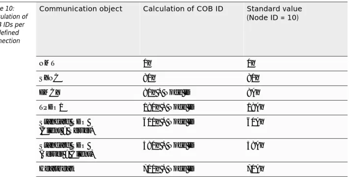
Table 10 displays the basis for calculation and the standard values (Node ID = 10).
Table 10:
Calculation of COB IDs per predefined connection set
Communication object Calculation of COB ID Standard value (Node ID = 10)
NMT 0h 0h
SYNC 80h 80h
EMCY 80h + Node ID 8Ah
TPDO1 180h + Node ID 18Ah
Standard SDO (Client > Server)
600h + Node ID 60Ah
Standard SDO (Server > Client)
580h + Node ID 58Ah
Heartbeat 700h + Node ID 70Ah
D101846 1801 - Inclinometers 5-17 Status LED (per CiA DR-303-3)
5.8 Status LED (per CiA DR-303-3)
The built-in two-color LED displays the current device status (Run LED, green), as well as CAN communication errors (Error LED, red) that might have occurred.
The different states are displayed in Table 11.
Table 11:
Status and error display
Status LED
Run LED, green LED status Description
Off The device is in the "reset" status or there is no power supply.
Blinking The device is in the
"pre-operational“ status.
Simple, short illumination The device is in the
"stopped" status.
On The device is in the
"operational" status.
Error LED, red LED status Description
Off The device operates error-free.
Simple, short illumination Error counter CAN controllers has reached the alarm threshold or overreached it.
Dual, short illumination The device recognized failure of the guarding master (Node Guard Event).
On The device is in the "bus off" status.
CANopen interface
5.9 EDS files
An electronic data sheet (EDS file) is available for each inclinometer (download free of charge from the internet under http://www.turck.com...).
It contains a complete description of the object register and can be easily added to a CANopen project planning software.
D101846 1801 - Inclinometers 6-1
6 Glossary
B Baud rate
Data transmission rate (1 Baud = 1 Bit/s)
C CAN
Controller Area Network
CANopen
Standardized application layer for CAN devices
CIA
CAN in Automation (membership corporation) CIA DS
CiA Draft Standard (specification published by CiA)
CIA DS-301
Specification of CANopen application layer and the communication parameters in the OD CIA DP
CiA Device Profile (device profile published by CiA) CIA DR
CiA Draft Standard (specification published by CiA) CIA DR-303-3
Recommended implementation for the display of CANopen device states and errors per LED
CIA DSP
CiA Draft Standard (specification published by CiA) CIA DSP-410
Specification draft of the device profile 410 for inclination sensors
Client
CANopen participant with utilization access to a server
COB
CANopen Communication Object
COB ID
CAN identifier of a COB
E EDS - electronic data sheet
Electronic data sheets which must be written according to a standardized text format. Configuration tools are suitable for reading EDS files, for communicating with the respective device and for parameterizing it if needed.
Glossary
EEPROM - Electrically Erasable Programmable Read-Only Memory
A non-volatile, electronic memory chip is called EEPROM. An EEPROM consists of a field effect transistor matrix with isolated floating gate in which each transistor represents a Bit.
EMCY
Emergency objects are triggered by a significant internal device error. An emergency message can only be sent once for each error. As long as the device remains free of additional errors, no additional emergency objects are sent. Error messages can be received by multiple emergency consumers. The response of the consumers depends on the application. CANopen defines Emergency Error Codes that are sent in the emergency object. The emergency object consists of a single CAN message with eight Byte data supported by standard emergency frames (EMCY) per CiA DS-301.
F Fieldbus
Data network on sensor- /actuator level. The devices on the field level are connected to a control unit by a fieldbus.
A fieldbus is recognized for high transmission integrity and real-time behavior.
FRAM - Ferroelectric Random Access Memory
A non-volatile, electronic storage type based on crystals with ferroelectrical characteristics is called FRAM.
G Guard COB ID
Identification number for Nodeguarding. This COB ID is fixed and can not be changed.
Guard Time
The request-interval time (display in milliseconds) to be expected from the network slave during Nodeguarding.
H Heartbeat
The Heartbeat protocol is used to monitor the operating ability of other CANopen bus participants. With the help of the Heartbeat signals, the CANopen node signals to all CANopen network participants that it is ready for operation even when no data transfer has occurred for an extended period of time. The failure of a CANopen node can be registered by all participants! The Heartbeat Producer Time determines the Heartbeat cycle time.
Hexadecimal (...h)
Number system with the basis 16. The count starts at 0 and ends at 9, and continues with the letters A, B, C, D, E and F.
IEC 61131 LI
IEC 61131 is an international standard which addresses the basic principles for controllers programmable from memory.
Inhibit Time
Minimum off-period for sending. With the help of Inhibit Time, an off-period between two signals is defined so that the bus is not continuously occupied by high priority messages. Is only supported for TPDOs
Initialization
D101846 1801 - Inclinometers 6-3 IP - International Protection
The protection class (IP) defines the suitability of electrical equipment (for example devices, installation material) for diverse environments and in addition, it determines the suitability for protecting persons against potential danger during operation of the electrical equipment.
L Lateral
Assignment of axes (Y-axis)
Lifetime Factor
This factor, multiplied by the Guard Time, determines the time that must pass after an error has occurred in the Nodeguarding protocol and before the error is signaled by the network slave per EMCY. This is how a communication difficulty that has temporarily occurred, for example high bus load, can be attended to without guarding error.
Longitudinal
Assignment of axes (X-axis)
Logistics
Logistics describes integral planning, control, execution, allocation, optimization and monitoring of processes for moving goods, data, energy and persons, as well as the needed transportation vehicles and equipment.
M Master
The Master controls the access conditions during a Master-Slave operation on the fieldbus level.
Mode
Operating mode (mode)
MSB
Most Significant Bit. Bit with the highest place value.
N NID
Node ID
Nodeguarding
Monitoring of the network nodes with the help of a network manager is called nodeguarding. In addition the CANopen network participants are used to check whether their network manager is still operating regularly and whether the network is still operating safely. Nodeguarding is inactive in the default setting. Different parameters must be set via the object register to activate a participant's nodeguarding protocol.
Node ID
Node number of a CANopen device (1...127)
NMT
Network Management Object (object to set and check CANopen device modes)
O Operational
CANopen device mode (SDO, PDO, EMCY, NMT possible)
OD
Object register (virtual register with device parameters, addressing per index and subindex).
P Parameterization
Setting of parameters of single bus participants or better their modules in the configuration software of the DP Master.
Glossary
Preoperational
CANopen device mode (SDO, PDO, EMCY, NMT possible)
Predefined Connection Set
Formula defined in the CiA DS-301 and to be used to calculate the COB IDs of the communication objects in reference to the Node ID.
Process Data Objects (PDOs)
Process data objects (PDO) are sent in a single CAN message. Here, all eight Byte of the data field can be used to send utilization objects. Each PDO must have a clear CAN identifier and must only be sent by one device. However, it can be received by multiple devices (Producer/ Consumer communication). PDO transmissions can be triggered by an internal event (event-driven), also by an internal timer (timer-driven) or by a request from another device.
R Repeater
In regards to digital communication technology, the repeater is a signal generator which receives a signal in the Bit transfer layer, then reprocesses and resends it. Noise as well as jitter of the run time and the pulse form are removed from the received signal with this type of processing.
RTR Remote Transmission Request
A set RTR Bit (Remote Transmission Request) identifies a remote frame (recessive). A participant may send a data transfer request to another participant with the help of a remote frame.
S Server
CANopen participant which offers a service for one/multiple client(s)
SDO - Service Data Objects
A service data object (SDO) reads data from the object register or writes data to the object register. The SDO transport protocol is suitable to send objects of different sizes. The first Byte of the first segment contains the needed flow control information. Among others it contains a toggle Bit to solve the problem of CAN messages that were received twice. The next three Byte of the first segment contain the index and subindex of the entry into the object register to be read or written. The last four Byte of the first segment are available for user data. The second and the following segments (which utilize the same CAN identifier) contain the control Byte and up to seven Byte user data. The receiver acknowledges each segment or a segment block so that a peer-to-peer communication (Client/Server) takes place.
Stopped
CANopen device mode (SDO, PDO, EMCY, NMT possible)
T Transmission Type
The transmission type determines under which circumstances a PDO will be sent or received.
U UNS8
Data type UNSIGNED8 (8 Bit, unsigned, 0...255) UNS16
D101846 1801 - Inclinometers 6-5