These instructions for use describe the structure, functions and use of the product and will assist you in operating the product as intended.
Target groups
Explanation of symbols used
Additional documents
Feedback about these instructions
Product identification
Scope of delivery
Legal requirements
Manufacturer and service
Turck assumes no responsibility for damages caused by failure to observe these warnings and safety instructions.
Intended use
General safety notes
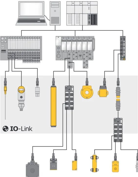
IO-Link technology is described in "IO-Link Interface and System Specification" and IEC 61131-9. The properties, functions and parameters of the IO-Link device are presented in the electronic device description (IODD). The IODD structure is defined by the IO-Link specification and is the same for all IO-Link devices.
Features
Signals and energy can be exchanged between any networks, fieldbuses and backplane buses via a digital, serial point-to-point connection. Each IO-Link system consists of an IO-Link master and an IO-Link device (e.g. sensor, I/O hub, valve block). The communication properties, device parameters, identification, process, diagnostic and device data are assigned to fixed indices in the IODD, through which the parameters can be controlled.
System architecture
Operating principle
Operating modes
IO-Link mode
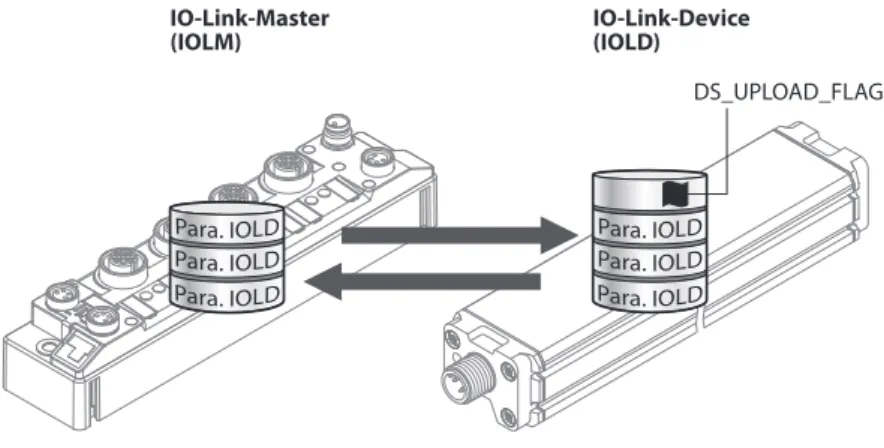
The data exchanged between the IO-Link master and the IO-Link device can be divided into cyclic process data and acyclic data. Data storage mode is only available for devices that comply with the IO-Link specification V1.1. The IO-Link master or IO-Link device saves the device parameters set in the previous configuration.
Standard I/O mode (SIO mode)
In data storage mode, the parameter data memory of IO-Link master and IO-Link device is synchronized. The IO-Link master module TBEN-L…-8IOL has eight IO-Link ports for connecting IO-Link devices. In addition to the eight IO-Link channels, four universal digital DXP channels (PNP) are available.
Device overview
Block diagram
Properties and features
Operating principle
Functions and operating modes
Multiprotocol technology
IO-Link channels
Configurable digital channels – functions
Mounting the device outdoors
Grounding the device
Equivalent wiring diagram and shielding concept
Shielding of the fieldbus and I/O level
Grounding the device – I/O level and fieldbus level
Using a screwdriver, position the ground terminal between the fieldbus connectors so that the terminal contacts the metal housing of the connectors. For mounting on a mounting plate: Secure the device with an M6 metal screw through the lower mounting hole.
Connecting the device to Ethernet
Connecting the power supply
Supply concept
Connecting IO-Link devices and digital sensors
Setting the IP address
Setting the IP address via switches at the device
DHCP mode 400 In DHCP mode, the full IP address is automatically assigned by a DHCP server on the network. In PGM mode, the set IP address and subnet mask are stored in the memory of the gateway. The DHCP client is automatically deactivated when an IP address is assigned to the gateway via the DTM or a web server.
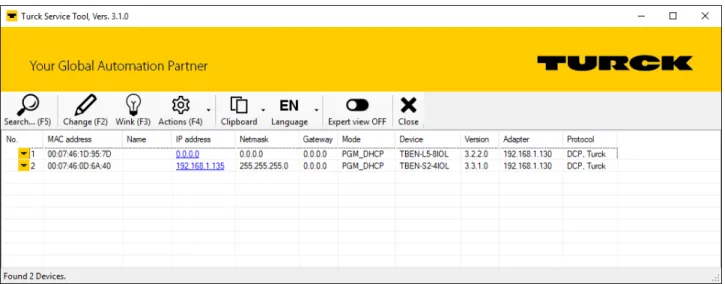
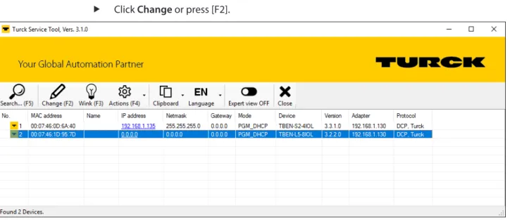
Setting the IP address with Turck Service Tool
To set the IP address via the web server, the device must be in PGM mode. Enter the device's new IP address, subnet mask, and default gateway via Send.
ARGEE/FLC
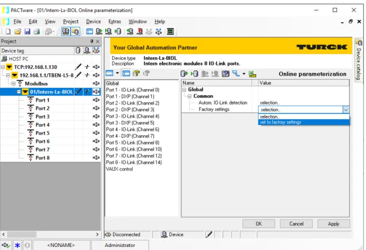
Commissioning an IO-Link device with IO-Link V1.0
Commissioning an IO-Link device with IO-Link V1.1
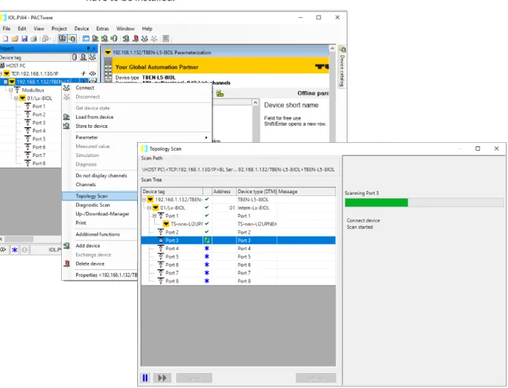
Read in connected IO-Link devices: topology scan in the DTM
Commissioning the device in PROFINET
- PROFINET IO device model
- Device model – TBEN-L…-8IOL
- Address setting in PROFINET
- FSU – Fast Start-Up (prioritized startup)
- MRP (Media Redundancy Protocol)
- User data for acyclic services
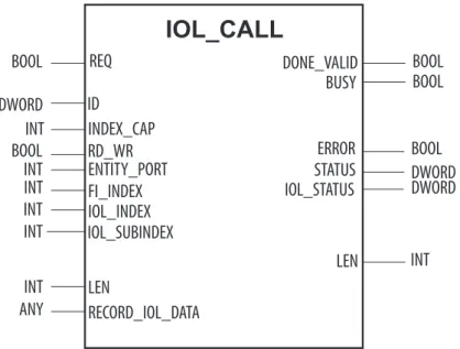
- The IO-Link function block IOL_CALL
The device name must meet the requirements of the Domain Name System (DNS) (see below). FI_INDEX INT Fixed value (65098): defines the access to be an IO-Link CALL IOL_INDEX INT Number of the IO-Link index to be read. 0xXX80C2XX RESOURCE_BUSY The IO-Link master module is busy or waiting for a response from the connected IO-Link device.
Connecting the device to a Siemens PLC in PROFINET
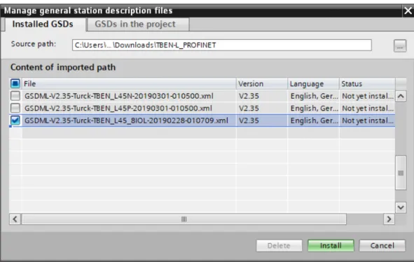
- Installing the GSDML file
- Connecting the devices to the PLC
- Assigning the PROFINET device name
- Setting the IP address in TIA Portal
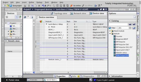
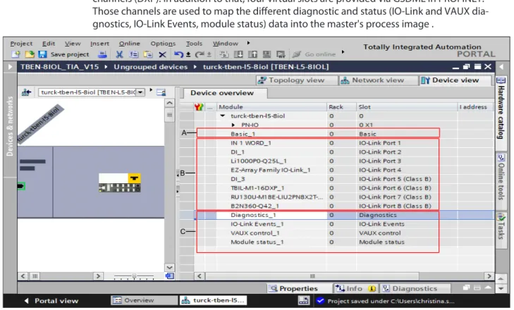
- Configuring device functions
- Going online with the PLC
- PROFINET – mapping
- Use the IO_LINK_DEVICE function block in TIA Portal
Basic parameters/diagnostics for the device's DXP channels (DXP 1, 3, 5 and 7) and valid data signal from the IO-Link ports. IO-Link Events Optional mapping of IO-Link events to the master process image. In the general port configuration, IO-Link master ports can be used in IO-Link mode with different configurations, as well as in SIO (DI) mode.
In specific port configuration, the IO-Link ports receive the parameters from the GSDML file. The IO_LINK_DEVICE function block is based on the IOL_CALL function block according to the IO-Link specification. Access to the port 0 functions of the IO-Link master with an IOL_INDEX of 65535 is not possible with version V3.0.2 of the Siemens IO_LINK_DEVICE block.
In this example, the lookup table Sensor1 serves to visualize the procedure of the read and write access via IO_LINK_DEVICE. The assignment of the SPDU indexes of IO-Link devices can be found in the respective device documentation. Read out the product name (product name, index 0x12) of the TURCK IO-Link I/O hub TBIL-M1-16DXP at IO-Link port 4.
Set the value to be written 0x05 via the first word of the IO-Link Record in the clock table.
Commissioning the device in Modbus TCP
- Implemented Modbus functions
- Modbus registers
- Data width
- Register mapping
- Error Behavior (watchdog)
0 At the first write access, a write authorization for the relevant Modbus connection is requested. If the request is accepted, the write access is executed and the write privilege remains active until the connection is broken. 1 The write permission for the respective Modbus connection has already been opened when the connection was established.
The first Modbus connection thus receives the write authorization, all subsequent connections do not (only if bit 0 = 1). This register defines after which time of inactivity a Modbus connection is closed through a Disconnect. If Modbus is the active protocol and all Modbus connections are closed, the watchdog switches all outputs on after the watchdog time has expired, unless another protocol (PROFINET, Ethernet/IP) has been activated in the meantime.
Commissioning the device in EtherNet/IP
Common EtherNet/IP features
EDS files and catalog files
Device Level Ring (DLR)
Diagnostic messages via process data
EtherNet/IP standard classes
The following description of the Ethernet Link Object is taken from the CIP specification, Vol. G UDINT Contains the identification number of the product (the last 3 bytes of the MAC ID). Refer to the TCP/IP object status diagram for details on the states of this status attribute.
The device must use the previously saved interface configuration (for example, from non-volatile memory, set by a hardware switch, etc.). If the value of the startup configuration bits (configuration control attribute) is 0, the new configuration is stored in non-volatile memory. The device does not respond to the specified service until the values are safely stored in non-volatile memory.
An attempt to set any of the components of the Interface Configuration attribute to invalid values results in an error (status code 0x09) returned from the Set service. If the initial configuration is obtained via BOOTP or DHCP, the Interface Configuration attribute components are all 0 until the BOOTP or DHCP response is received. Upon receiving the BOOTP or DHCP response, the Interface Configuration attribute displays the configuration obtained via BOOTP/DHCP.
The hostname attribute is used when the device supports the DHCP-DNS update capability and has been configured to use DHCP at startup.
VSC-Vendor Specific Classes
The IO-Link parameter object enables the acyclic transfer of parameter data between the IO-Link master and the IO-Link device. The instance attribute numbers address the IO-Link port at the IO-Link master or the port 0 functions of the IO-Link master. Data byte 0 Index (LSB) UINT LSB from index of the IO-Link ISDU object acc.
Data byte 1 Index (MSB) UINT MSB from ISDU IO-Link object index po. Instance Attribute 0x04 IO-Link Port Number Service Code 0x4B Read_ISDU: Access to read data request parameters for ISDU read service. IOL_Master UINT IO-Link master-specific error, see IO-Link master error codes. IOL_Device Error UINT specific to an IO-Link device, see IO-Link Device Error Codes.
Instance attribute 0x04 IO-Link port number Service code 0x4C Write_ISDU: Write access Data request parameters for the ISDU write service. Possible source: the addressed port is parameterized as digital input DI and is not in IO-Link mode 0x1100 I_SERVICE_TIMEOUT Timeout in communication, the device does not repeat. This class provides one instance per IO-Link port on the IO-Link master module.
1 = IO-Link with family compatible device 2 = IO-Link with compatible device 3 = IO-Link with identical device 4 = DI (with parameter access) 5…7 = reserved.
Connecting the Devices to a Rockwell PLC with EtherNet/IP
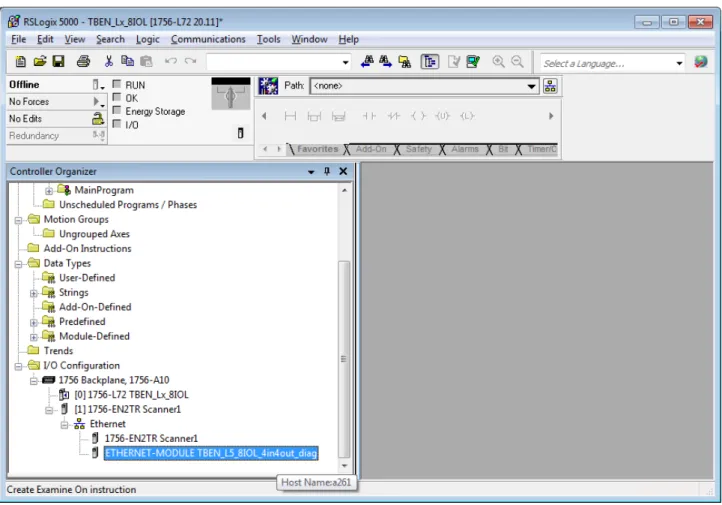
Adding the devices from the catalog files to the new project
Right-click on the EtherNet/IP-Scanner in the second step of RS Logix and add the device to the project via Paste. In this example, the configuration with 4 bytes output data and 4 bytes plus TBEN_L5_8IOL_4in4out_diag diagnostics is used.
Configuring the device in RS Logix
Parameterizing the device
Going online with the PLC
Reading process data
If the master detects a mismatch, IO-Link communication is established, but there is no process data exchange. If the master detects a mismatch, IO-Link communication is established, but there is no process data change. Data storage mode Synchronization of parameter data of IO-Link devices (parameter storage of the connected device in the master).
The start-up time (TSD = Device Detection Time) defined in the IO-Link specification is reduced. 1 0x01 Notifications The master sends all IO-Link events to the fieldbus except IO-Link notifications. The master sends all IO-Link events to the fieldbus, except IO-Link messages and warnings.
The mapping of process data can be adapted application-specifically via the IO-Link master's parameterization. A distinction must be made between data from the IO-Link master (IOLM) and data from connected IO-Link devices (IOLD). The object writes a specific configuration of the devices to be connected to the IO-Link port of the master.
The object reads the configuration of the IO-Link devices connected to the IO-Link master.
Software diagnostic messages
Status- and control word
Diagnostic telegram
The connected device is not in the "served" status, which means that it is not ready for use. For more detailed information about the diagnostics, please refer to the documentation for the IO-Link device. The process value exceeds the parameterized measuring range or the selected measuring range is selected too low.
PROFINET diagnostics
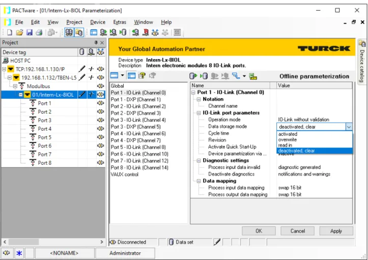
Using the data storage mode
- Parameter ”data storage mode” = activated
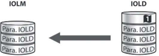
- Parameter ”data storage mode” = read in
- Parameter ”data storage mode” = overwrite
- Parameter ”data storage mode” = deactivated, clear
In this case, turn off the device and replace it with a new device of the same type.
Eliminate parameterization errors
Carry out firmware update via FDT/DTM
Returning devices
Output voltage 24 VDC from potential group Output current per channel 2 A, short-circuit proof Potential isolation Galvanic isolation for P1/P2,. Applies to operation at ambient temperatures defined below with adequate ventilation and maximum load (horizontal nominal position). At ambient temperatures of < 30 °C, the units can also be mounted directly next to each other.
This equipment has been tested and found to comply with the limits for a Class A digital device, pursuant to Part 15 of the FCC Rules. These limits are designed to provide reasonable protection against harmful interference when the equipment is operated in a commercial environment. This equipment generates, uses and can radiate radio frequency energy and, if not installed and used in accordance with the instructions for use, may cause harmful interference to radio communications.
Operation of this equipment in a residential area is likely to cause harmful interference in which case the user will be required to correct the interference at his own expense.