Your Global Automation Partner
PS310… | PS510…
Pressure Sensors
Contents
1 About these Instructions... 5
1.1 Target groups... 5
1.2 Explanation of symbols used ... 5
1.3 Other documents ... 5
1.4 Feedback about these instructions... 5
2 Notes on the Product ... 6
2.1 Product identification... 6
2.2 Scope of delivery ... 6
2.3 Legal requirements... 6
2.4 Manufacturer and service ... 7
3 For Your Safety... 8
3.1 Intended use... 8
3.2 Obvious misuse... 8
3.3 General safety instructions... 8
4 Product Description ... 9
4.1 Device overview ... 9
4.2 Properties and features... 9
4.3 Operating and display functions... 9
4.4 Operating principle... 10
4.5 Functions and operating modes ... 10
4.5.1 Setting options ... 10
4.5.2 Normal operation – Run mode ... 10
4.5.3 Menu mode... 10
4.5.4 Programming mode ... 10
4.5.5 Output functions – Switching output ... 11
4.5.6 Output functions – Analog output... 12
4.5.7 IO-Link mode ... 12
4.6 Technical accessories... 13
5 Installing... 14
6 Connecting ... 15
6.1 Wiring diagrams ... 15
7 Commissioning ... 16
8 Operation ... 17
8.1 LED status indications – Operation... 17
8.2 Display indications... 17
8.3 Display indications – Diagnostic messages... 18
9 Setting ... 19
9.1 Setting via touchpads... 22
9.1.1 Unlocking the touchpads... 22
9.1.2 Locking the touchpads ... 22
9.1.3 Setting parameter values via touchpads... 22
9.1.4 Parameters in the main menu... 23
9.1.5 Parameters in the EF submenu (Extended Functions) ... 24
Contents
10 Troubleshooting ... 27
11 Maintenance... 28
12 Repair... 28
12.1 Returning devices... 28
13 Disposal ... 28
14 Technical Data... 29
1 About these Instructions
These operating instructions describe the structure, functions and the use of the product and will help you to operate the product as intended. Read these instructions carefully before using the product. This is to avoid possible damage to persons, property or the device. Retain the in- structions for future use during the service life of the product. If the product is passed on, pass on these instructions as well.
1.1 Target groups
These instructions are aimed a qualified personal and must be carefully read by anyone mounting, commissioning, operating, maintaining, dismantling or disposing of the device.
1.2 Explanation of symbols used
The following symbols are used in these instructions:
DANGER
DANGER indicates a dangerous situation with high risk of death or severe injury if not avoided.
WARNING
WARNING indicates a dangerous situation with medium risk of death or severe in- jury if not avoided.
CAUTION
CAUTION indicates a dangerous situation of medium risk which may result in minor or moderate injury if not avoided.
NOTICE
NOTICE indicates a situation which may lead to property damage if not avoided.
NOTE
NOTE indicates tips, recommendations and useful information on specific actions and facts. The notes simplify your work and help you to avoid additional work.
u
CALL TO ACTIONThis symbol denotes actions that the user must carry out.
a
RESULTS OF ACTIONThis symbol denotes relevant results of actions.
1.3 Other documents
Besides this document the following material can be found on the Internet at www.turck.com:
n Data sheet n Quick-Start Guide
n IO-Link parameters manual
n Commissioning manual IO-Link devices
1.4 Feedback about these instructions
We make every effort to ensure that these instructions are as informative and as clear as pos- sible. If you have any suggestions for improving the design or if some information is missing in the document, please send your suggestions to [email protected].
Notes on the Product
Legal requirements
2 Notes on the Product
2.1 Product identification
X Special version Special version
X Peak pressure aperture
PS 310 – 1V – 03 – LI2UPN 8 – H1 1 4 1 PS 310 Measuring cell –
Measuring cell
310 Ceramic measuring cell 510 Metal measuring cell Functional principle PS Pressure sensor
1V Measuring range –
Measuring range Ceramic measuring cell OV -1 … 0 bar 1V -1 … 1 bar
1 0 … 1 bar
1A 0 … 1 bar absolute 2.5V -1 … 2.5 bar 2.5 0 … 2.5 bar 2.5A 0 … 2.5 bar absolute Metal measuring cell 10V -1 … 10 bar 10 0 … 10 bar 10A 0 … 10 bar absolute 16 V -1 … 16 bar 16A 0 … 16 bar absolute 25V -1 … 25 bar 25A 0 … 25 bar absolute 40V -1 … 40 bar 100 0 … 100 bar 250 0 … 250 bar 400 0 … 400 bar 600 0 … 600 bar
03 Mechanical version –
Mechanical version 01 G1/4" female thread 02 1/4"-18NPT female thread 03 1/4"-18NPT male thread 04 G1/4" male thread 05 7/16" UNF male thread 08 G1/2" manometer
LI2UPN 8 Electrical version / Operating voltage
8 18...30 VPC Output function
2UPN 2 switching outputs/
IO-Link LI2UPN Current and
switching output/
IO-Link
H1 1 4 1 Electrical connection:
connector /
Assignment
1 Standard assignment Number of contacts 4 4 Contacts Alignment 1 Straight Design H1 Connector
M12 × 1
2.2 Scope of delivery
The scope of delivery includes:
n Pressure sensor
2.4 Manufacturer and service
Hans Turck GmbH & Co. KG Witzlebenstraße 7
45472 Mülheim an der Ruhr Germany
Turck supports you with your projects, from initial analysis to the commissioning of your applic- ation. The Turck product database contains software tools for programming, configuration or commissioning, data sheets and CAD files in numerous export formats. You can access the product database at the following address: www.turck.de/products
For further inquiries in Germany contact the Sales and Service Team on:
n Sales: +49 208 4952-380 n Technology: +49 208 4952-390
Outside Germany, please contact your local Turck representative.
For Your Safety
General safety instructions
3 For Your Safety
The product is designed according to state-of-the-art technology. However, residual risks still exist. Observe the following warnings and safety notices to prevent damage to persons and property. Turck accepts no liability for damage caused by failure to observe these warning and safety notices.
3.1 Intended use
The devices are intended for use in the industrial sector.
The pressure sensors of the PS series monitor media belonging to fluid group 2 and show the measured values in a display. The sensors are vacuum-tight.
The devices may only be used as described in these instructions. Any other use is not in accord- ance with the intended use. Turck accepts no liability for any resulting damage.
3.2 Obvious misuse
n The devices are not safety components and must not be used for personal or property pro- tection.
3.3 General safety instructions
n The device only meets the EMC requirements for industrial areas and is not suitable for use in residential areas.
n The device may only be assembled, installed, operated, parameterized and maintained by professionally-trained personnel.
n The device may only be used in accordance with applicable national and international regu- lations, standards and laws.
n The maximum permissible overpressure must not be exceeded.
4 Product Description
The pressure sensors of the PS+ series are contained in a metal housing with a display and are available with different process connections. The housing can also be aligned and fastened as required after mounting. All devices are provided with a metal-bodied M12 connector for con- necting the sensor cable.
The devices can be set via the touchpads, FDT/DTM or IO-Link. The measured pressure can be displayed in bar, psi, kPa, MPa and in ten other units of pressure (Ud1...Ud10).
Devices with the following output functions are available for selection:
n PS…2UPN8…: Two switching outputs (PNP/NPN)
n PS…LI2UPN8…: One switching output (PNP/NPN) as well as one switching output (PNP/
NPN) or one analog output (adjustable as current or voltage output)
4.1 Device overview
24
91.5 [3.60]
ø 38 [1.50]
Electrical Connection
Process Connection L
55.1 [2.17]
12.2 [0.48]
Fig. 1: Dimensions in mm [inch]
4.2 Properties and features
n Pressure monitoring of fluid group 2 n IO-Link 1.1
n Automatic signal detection
n Up to 7-fold overpressure resistance n Protection types IP6K6K, IP6K7, IP6K9K n 180° invertible multi-color display n Rotatable sensor body
n Stainless steel housing 1.4305 (AISI 303) or 1.4404 (316 L) n Electronic output:
– 1 PNP/NPN output + 1 analog or PNP/NPN output – 2 PNP/NPN outputs
4.3 Operating and display functions
The front of the device is provided with three touchpads [ENTER], [MODE] and [SET], a 4-digit 12-segment multicolor display and status LEDs. This enables the user to set all essential func- tions and properties directly on the device and read the actual process values and taught switch points.
Product Description
Functions and operating modes
4.4 Operating principle
The pressure sensors of the PS310 series operate with ceramic measuring cells. The pressure ex- erted on the ceramic carrier generates a signal proportional to the pressure, which is then elec- tronically processed. Depending on the sensor version, the processed signal is converted either into a switching or an analog output with an accuracy of 0.5 % of full scale.
The pressure sensors of the PS510 series operate with fully welded metal measuring cells. The pressure exerted on the metal carrier material generates a signal proportional to the pressure, which is then electronically processed. Depending on the sensor version, the processed signal is converted either into a switching or an analog output with an accuracy of 0.25 % of full scale.
4.5 Functions and operating modes
The sensors of the PS series monitor media belonging to fluid group 2 and show the measured values in a display.
The device parameters can be set via IO-Link and with the touchpads. A window function and a hysteresis function can be set for the switching outputs. The measuring range of the analog output can be defined as required. The measured pressure is displayed in bar, psi, kPa, MPa and 10 other units of pressure (Ud1...Ud10).
Type Output
PS…2UPN8… Two switching outputs (PNP/NPN)
PS…LI2UPN8… One switching output (PNP/NPN) as well as one switching output (PNP/NPN) or one analog output (adjustable as current or voltage out- put)
4.5.1 Setting options
The devices offer three setting options:
n Setting via IO-Link n Setting via the touchpads n Setting via FDT/DTM
4.5.2 Normal operation – Run mode
The sensor detects the system pressures and shows the measured process values according to the preset switching and analog behavior. The display indicates the system pressure present, the selected unit and the status of the switching outputs present.
4.5.3 Menu mode
Pressing the [MODE] touchpad switches the display to Menu mode. In this mode all parameters and the associated values can be read. A short press of the [SET] touchpad displays the values of a parameter.
4.5.4 Programming mode
Programming mode enables the setting of all adjustable parameter values. A short press of the [SET] touchpad displays the values of a parameter.
4.5.5 Output functions – Switching output
A window function and a hysteresis function can be set for the switching outputs.
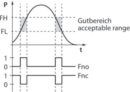
Window function
The window function is used to teach a switching range in which the switching output takes on a defined switching state. The switching range is defined by an upper and lower limit value. The minimum distance between the limit values is 0.5 % of the nominal pressure range. If the upper limit value is changed, the lower limit value is automatically adjusted.
P FH
1 FL
t
0 1 0
Fno Fnc Gutbereich acceptable range
Fig. 2: Behavior of the switching output (window function)
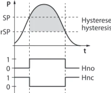
Hysteresis function
The hysteresis function ensures a stable switching state that is not affected by system-related pressure fluctuations and the adjusted setpoint. The switching range is defined with a switch point and a reset point. The minimum hysteresis is 0.5 % of the nominal pressure range. If the switch point is changed, the reset point is automatically adjusted.
P SP
1 rSP
t
0 1 0
Hno Hnc Hysterese hysteresis
Fig. 3: Behavior of the switching output – Hysteresis function
Product Description
Functions and operating modes
4.5.6 Output functions – Analog output
The analog output of the PS…LI2UPN8 sensors can be set as either a current or voltage output.
The measuring range is freely definable.
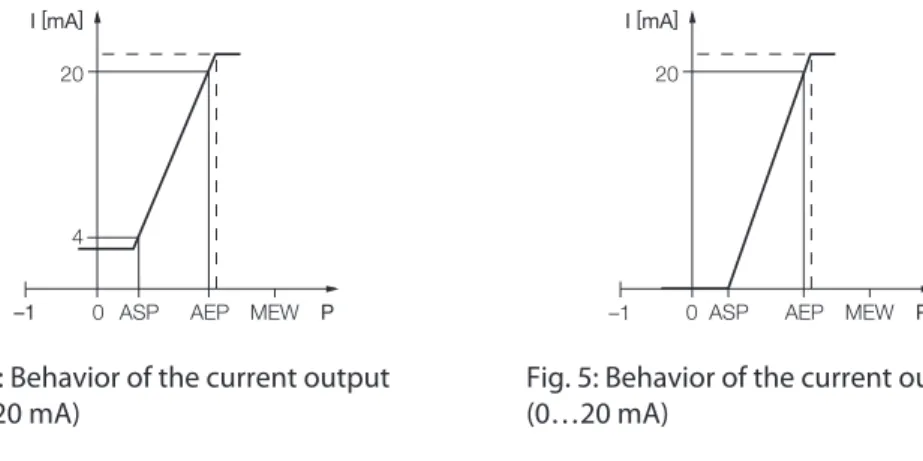
Current output
In the defined measuring range between ASP (analog start point) and AEP (analog end point), the output signal is between 4 and 20 mA or between 0 and 20 mA. The minimum distance between the start and end point is 10 % of the set measuring range.
I [mA]
4
AEP P
20
1 0 ASP MEW
I [mA]
AEP P
20
0
1 ASP MEW
Fig. 4: Behavior of the current output (4… 20 mA)
Fig. 5: Behavior of the current output (0…20 mA)
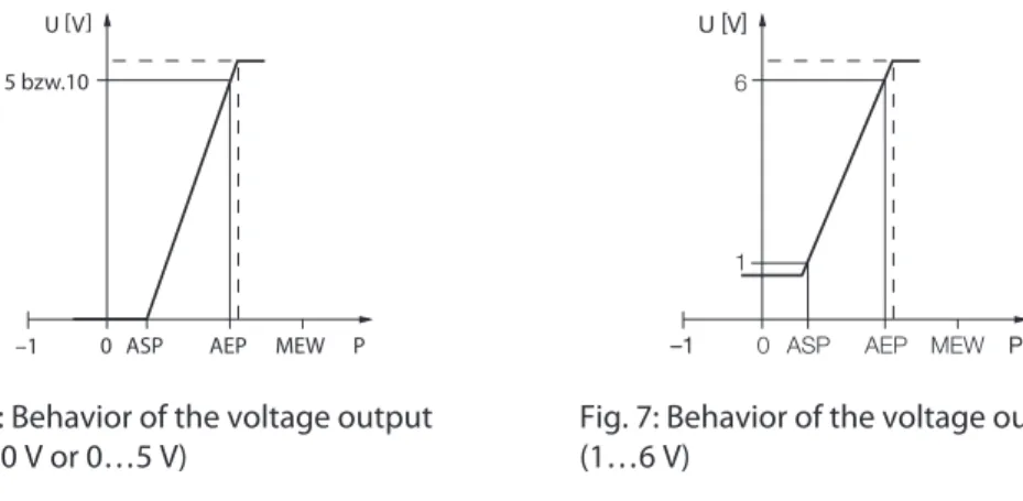
Voltage output
In the defined measuring range between ASP (analog start point) and AEP (analog end point), the output signal is between 0 and 10 V, between 0 and 5 V, or between 1 and 6 V.
U [V]
AEP P
0
1 ASP MEW
5 bzw.10
U [V]
1
AEP P
6
1 0 ASP MEW
Fig. 6: Behavior of the voltage output (0…10 V or 0…5 V)
Fig. 7: Behavior of the voltage output (1…6 V)
4.5.7 IO-Link mode
The devices must be connected to an IO-Link master for operation in IO-Link mode. If the port is configured in IOL mode, bidirectional IO-Link communication is provided between the IO-Link master and the device. For this the device is integrated in the controller level via an IO-Link master. The communication parameters are exchanged first of all; the cyclic data exchange of the process data (process data objects) then starts.
4.6 Technical accessories
Type name Description Figure
WKC4.4T-2-RSC4.4T/TXL Connection cable, M12 female connector, angled to M12 con- nector, straight, 4-pin, cable length: 2 m, sheathing mater- ial: PUR, green; cULus approval
26.5 M12 x 1 ø 15
32 14
L
14M12 x 1 ø 15
49.5 18.2
WKC4.4T-2/TXL Connection cable, M12 female connector, angled, 4-pin, cable length: 2 m, sheathing material: PUR, black; cULus ap- proval
26.5 M12 x 1 ø 15
32 14
L
50 5
USB-2-IOL-0002 IO-Link adapter with integ- rated USB interface
41
24
54
M12 x 1 16
USB-Mini IN-DC LED:
CH1 (C/Q) CH2 (DI/DO) Error
LED: PWR
PAM-P3 Pressure peak aperture for
mounting on the process con- nection
In addition to the above connection cables, Turck also offers other cable types for specific ap- plications with the correct terminals for the device. More information on this is provided in the Turck product database at www.turck.de/products in the Connectivity area.
Installing
5 Installing
Fig. 8: Vertical mounting Fig. 9: Horizontal mounting
Depressurize the installation before mounting.
Do not install the device at a location where high pressure pulses can occur.
Fit the device to the pressure connection using the corresponding counterpiece as shown in the figure.
Note the different pressure connections.
Mount the sensor in any direction.
The display of the unit can be rotated by 180°.
The maximum tightening torque for fastening the sensor is 35 Nm (15 Nm for 7/16 UNF).
The housing can be rotated by 340°.
Severe temperature changes in the environment of the sensor can cause the shifting of the zero point. In this case, the displayed measured value will not be zero when the sensor is in a depressurized state. If the zero point is offset, an offset value can be set via the CoF parameter (see chapter “Settings”).
6 Connecting
Connect the female connector of the connection cable to the male connector of the sensor.
Connect the open end of the connection cable to the power supply and/or processing units.
6.1 Wiring diagrams
3 2
4 1
1 L + 3 L – 2 out 2 switch 4 out 1 switch/IO-Link
Fig. 10: Pin layout PS…2UPN… Fig. 11: Wiring diagram PS…2UPN…
3 2
4 1
1 BN + 3 BU – 2 WH out 2 / IA 4 BK out 1 / IO-Link
Fig. 12: Pin layout PS…LI2UPN… Fig. 13: Wiring diagram PS…LI2UPN…
Commissioning
7 Commissioning
The device is operational automatically once the power supply is switched on.
8 Operation
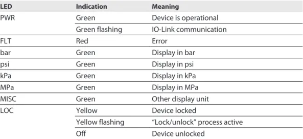
8.1 LED status indications – Operation
LED Indication Meaning
PWR Green Device is operational
Green flashing IO-Link communication
FLT Red Error
bar Green Display in bar
psi Green Display in psi
kPa Green Display in kPa
MPa Green Display in MPa
MISC Green Other display unit
LOC Yellow Device locked
Yellow flashing “Lock/unlock” process active
Off Device unlocked
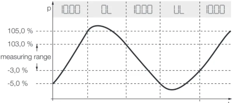
8.2 Display indications
Display Meaning
Flashing Measured value out of analog range
OL Value outside of the measuring range, pressure more than 5 % of full scale above the limit value
UL Value outside of the measuring range, pressure more than 5 % of full scale below the limit value
SC1 Short circuit at output 1
SC2 Short circuit at output 2
SC12 Short circuit at both outputs
boot EEPROM error
Loc Device locked
uLoc Device unlocked
---- Sensor failure
AEP + 2%
AEP
ASP ASP 2%
t p
analog range
Fig. 14: Display – Value within the set measuring range
Operation
Display indications – Diagnostic messages
105,0 % 103,0 %
-3,0 % -5,0 %
t p
measuring range
Fig. 15: Display indications – Value outside the set measuring range
8.3 Display indications – Diagnostic messages
Display Meaning
ErrP Error in measuring cell
ErrC Communication error
ErrA Ambient pressure error
SC1 Short circuit at output 1 SC2 Short circuit at output 2 SC12 Short circuit at both outputs ErrL Error on electrical resistance
Err Undefined error
… Sensor failure
OL Value outside of the measuring range, > 5 % of full scale above limit UL Value outside of the measuring range, > 5 % of full scale below limit
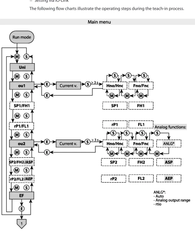
9 Setting
The device can be assigned parameters as follows:
n Setting via touchpad n Setting via IO-Link
The following flow charts illustrate the operating steps during the teach-in process.
Fig. 16: Overview of the teach main menu
Setting
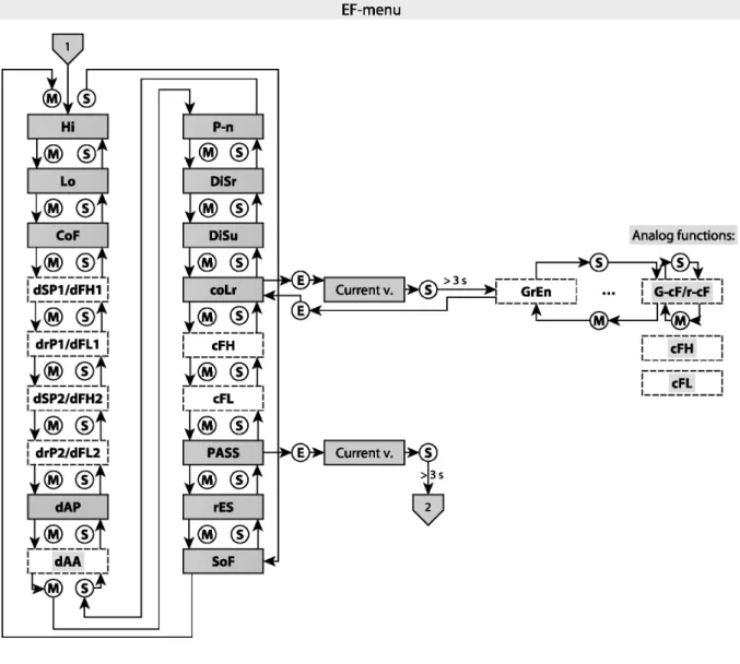
Fig. 17: Overview of the teach EF menu
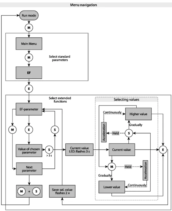
Fig. 18: Overview of the menu navigation
Setting
Setting via touchpads
Fig. 19: Password setting
9.1 Setting via touchpads
Use the [MODE], [SET] or [ENTER] touchpads to set the parameters.
9.1.1 Unlocking the touchpads
Touch [ENTER] for 3 s until all green bars are flashing on the display.
Swipe the [MODE], [ENTER], [SET] touchpads in that order in succession: Two red flashing bars appear on the display when each touchpad is touched.
Swipe the next touchpad once the two red bars turn green.
Release the touchpads when six green bars are lit on the display.
a LED LOC flashes first and then goes out.
9.1.2 Locking the touchpads
Touch and hold down [MODE] and [SET] for 3 s.
a LOC flashes first and then is permanently lit yellow.
The sensor is automatically locked if the touchpads of the sensor are not actuated for 1 min.
9.1.3 Setting parameter values via touchpads
If the display shows a red running light when [MODE] and [SET] are touched, unlock the device.
Touch [MODE] or [SET] until the required parameter appears in the display.
Touch [ENTER] to select the parameter.
Changing the displayed value: Touch [SET] for 3 s until the display is no longer flashing.
Increase or decrease the value gradually via [MODE] or [SET]. Certain values can also be continuously changed by holding down [MODE] or [SET].
9.1.4 Parameters in the main menu
Explanation Options Function
Uni Display unit bar bar
psi psi
kPa kPa
MPa MPa
Ud1 mBar
Ud2 Torr = mmHg (0 °C)
Ud3 Inch of water (60 °F)
Ud4 Inch of water (39 °F)
Ud5 Foot of water (39 °F)
Ud6 Inch of Hg (60 °F)
Ud7 Inch of Hg (32 °F)
Ud8 mH20 (16 °C)
Ud9 mH20 (4 °C)
Ud10 kg/Cm2
ou1 Function of output 1 Hno Hysteresis function (NO contact)
Hnc Hysteresis function (NC contact)
Fno Window function (NO contact)
Fnc Window function (NC contact)
SP1 Switching point 1 for hysteresis function
ou1: Hno/Hnc
Upper limit value at which output 1 changes its switching state when the pressure increases rP1 Reset switching point 1
for hysteresis function ou1: Hno/Hnc
Lower limit value at which output 1 changes its switching state when the pressure drops FH1 Upper switch point for window
function ou1: Fno/Fnc
Upper switch point at which output 1 changes its switching state
FL1 Lower switch point for window function
ou1: Fno/Fnc
Lower switch point at which output 1 changes its switching state
ou2 Function of output 2 Hno Hysteresis function (N/O = NO contact)
Hnc Hysteresis function (N/C = NC contact)
Window function Fno Window function (N/O = NO contact)
Fnc Window function (N/C = NC contact)
Setting
Setting via touchpads
Explanation Options Function
ou2 Analog output auto
4-20 4…20 mA
0-20 0…20 mA
20-4 20…4 mA
20-0 20…0 mA
0-10 0…10 V
0-5 0…5 V
1-6 1…6 V
10-0 10…0 V
5-0 5…0 V
6-1 6…1 V
rtio 0.5…4.5 V
SP2 Switching point 2 ou2: Hno/Hnc
Upper limit value at which output 2 changes its switching state when the pressure increases
rP2 Reset point 2
ou2: Hno/Hnc
Lower limit value at which output 2 changes its switching state when the pressure drops FH2 Upper switch point for window
function ou2: Fno/Fnc
Upper switch point at which output 2 changes its switching state
FL2 Lower switch point for window function
ou2: Fno/Fnc
Lower switch point at which output 2 changes its switching state
ASP Start point of the analog signal ou2: Auto/analogvalues/rtio
Pressure value at which the analog signal has its start point
AEP End point of the analog signal ou2: Auto/analogvalues/rtio
Pressure value at which the analog signal has its end point
EF Submenu for additional setting options
See table “Parameters in the EF submenu”
9.1.5 Parameters in the EF submenu (Extended Functions)
Explanation Options Function
Hi Maximum value memory The highest pressure is stored and can be dis-
played/deleted here.
Lo Minimum value memory The lowest pressure is stored and can be dis-
played/deleted here.
CoF Offset adjustment Severe temperature changes in the environ-
ment of the sensor can cause the shifting of the zero point. In this case, the displayed measured value will not be zero when the sensor is in a depressurized state. An offset
Explanation Options Function
dFH1 Switch delay of FH1 0…60 s in increments of 0.1 s (0 = delay time
not active), only available with window mode Fno or Fnc
dFL1 Switch delay of FL1 0…60 s in increments of 0.1 s (0 = delay time
not active), only available with window mode Fno or Fnc
dSP2 Switch delay of SP2 0…60 s in increments of 0.1 s (0 = delay time
not active).
drP2 Switch delay of rP2 0…60 s in increments of 0.1 s (0 = delay time
not active).
dFH2 Switch delay of FH2 0…60 s in increments of 0.1 s (0 = delay time
not active), only available with window mode Fno or Fnc
dFL2 Switch delay of FL2 0…60 s in increments of 0.1 s (0 = delay time
not active), only available with window mode Fno or Fnc
dAP Damping of switching output (fil- ter)
Momentary or high frequency pressure peaks can be filtered: 0…8 s in increments of 0.01 s (0 = filter is deactivated)
dAA Damping of the analog output Filter for momentary or high frequency pres- sure peaks: 0… 8 s in increments of 0.01 s (0 = filter is deactivated)
P-n Behavior of the switching output auto
npn n switching
pnp p switching
diSr 0° Display rotated by 0°
180° Display rotated by 180°
diSu Measured value display 50 50 ms update time
200 200 ms update time
600 600 ms update time
Off Display update deactivated
coLr Display color GrEn Display is always green.
rEd Display is always red.
G1ou Display is green if ou1 is switched, otherwise red.
r1ou Display is red if ou1 is switched, otherwise green.
G2ou Display is green if ou2 is switched, otherwise red.
r2ou Display is red if ou2 is switched, otherwise green.
G-cF Display is green if the measured value is between switching points cFL and cFH.
r-cF Display is red if the measured value is between switching points cFL and cFH.
Setting
Setting via IO-Link
Explanation Options Function
PASS Password protection Define password and activate password pro-
tection
0000 No password
rES Reset FacT Reset the parameters to the factory setting
Undo Reset of the parameters since the last unlock- ing of the sensor
SOF Software version
9.2 Setting via IO-Link
The device can be parameterized within the technical specifications (see data sheet) via the IO- Link communication interface – both offline, e.g. with the configuration tool as well as also on- line via the controller. An overview of the different functions and properties that can be set and used for IO-Link or SIO mode can be found in the chapter “Setting” and in the IO-Link para- meter manual of the device. Detailed instructions on the parameterization of devices via the IO- Link interface are provided in the IO-Link commissioning manual.
All the parameters can be changed in IO-Link mode via the controller during commissioning as well as during operation. In SIO mode the device operates according to the last setting made in IO-Link mode.
10 Troubleshooting
If the device does not function as expected, first check whether ambient interference is present.
If there is no ambient interference present, check the connections of the device for faults.
If there are no faults, there is a device malfunction. In this case, decommission the device and replace it with a new device of the same type.
Maintenance
Returning devices
11 Maintenance
Ensure that the plug connections and cables are always in good condition.
The devices are maintenance-free, clean dry if required.
12 Repair
The device must not be repaired by the user. The device must be decommissioned if it is faulty.
Observe our return acceptance conditions when returning the device to Turck.
12.1 Returning devices
Returns to Turck can only be accepted if the device has been equipped with a Decontamination declaration enclosed. The decontamination declaration can be downloaded from
https://www.turck.de/en/retoure-service-6079.php
and must be completely filled in, and affixed securely and weather-proof to the outside of the packaging.
13 Disposal
The devices must be disposed of correctly and must not be included in normal household garbage.
14 Technical Data
Type code PS 310 PS 510
Pressure range Sensor-dependent
See data sheet Pressure type
Outputs Transistor switching output, analog outputs and IO-Link (freely configurable)
IO-Link COM2 38.4 kBaud frame type 2.2
Current output (0) 4…20 mA
Voltage output 0…10 V, 0…5 V, 1…6 V
Accuracy of analog output (NLHR), non-linearity, hyster- esis and repeatability
Sensor-dependent See data sheet Switching output
Accuracy/switch point Switching point distance Switch point
Reset switch points Switching frequency
Operating voltage 18…33 VDC
Temperature of medium -40…+90 °C
Ambient temperatur -40…+80 °C
Storage temperature -40…+100 °C
TK: – Zero point/10K – Range/10K
Voltage drop at Ie
Burst protection Sensor-dependent
See data sheet Short-circuit/reverse polarity
protection
Yes, cyclic / yes (power supply)
Rated operational current 0.25 A
Type of protection IP6K6K/IP6K7/IP6K9K acc. to ISO 20653
Protection class III
EMC EN 61000-4-2
EN 61000-4-3 EN 61000-4-4 EN 61000-4-5 EN 61000-4-6
Housing material Stainless steel/plastic, 1.4404 (316L)/ polyarylamide 50% GF UL 94 V-0
Materials with medium-con- tact
Stainless steel 1.4404 (316L) , Al2O3, FKM (Viton)
Stainless steel 1.4404 (316L) / 1.4542
Pressure connection wrench size
24
Technical Data
Type code PS 310 PS 510
Housing nut with tightening torque
35 Nm
Rotatable display Yes
Sensor body adjustable Yes
Vibration resistance 20 g (10…2000 Hz) acc. to EN 60068-2-6
Shock resistance 50 x g (11 ms) acc. to EN 60068-2-27
Type of display 4-digit 12-segment display, rotatable by 180°. Red or green.
Number of touchpads 3
![Fig. 1: Dimensions in mm [inch]](https://thumb-ap.123doks.com/thumbv2/azpdforg/10213333.0/9.892.81.715.226.1122/fig-dimensions-in-mm-inch.webp)