Numerical Simulation of Stress Shielding Induced by Crack Interaction in Human Phalanx Bone
by
Siti Aisyah Binti Abdul Halim (1332120845)
A dissertation submitted in partial fulfillment of the requirement for the degree of Master of Science (Engineering Mathematics)
Institute of Engineering Mathematics UNIVERSITI MALAYSIA PERLIS
2014
© This
item is protecte d by
original
copyr
ight
ii
ACKNOWLEDGEMENT
First of all, praise to Allah s.w.t who had given me the strength and health to complete this dissertation thus completing MSc. Engineering Mathematics. Firstly, I would like to say thank you to Mr. Wan Zuki Azman Wan Muhamad, my supervisor and Dr. Ruslizam Daud, my co-supervisor, for their knowledge and helpful guidance throughout this project. Their knowledge and guidance is very important to me to finish this project.
Also, my acknowledgment is dedicated to all of my friends for their helping throughout this project. Then, a special gratitude to my coordinator program, Dr. Muhammad Zaini Ahmad for his effort to manage and guide me in the dissertation sessions. Not forgotten to all members and staff of Institute of Engineering Mathematics and my beloved family for all the caring, encouragement and support they had given towards me.
Last but not least, thank you to all other contributors during the completing this Dissertation study.
© This
item is protecte d by
original
copyr
ight
iii
TABLE OF CONTENTS
PAGE
THESIS DECLARATION i
ACKNOWLEDGEMENT ii
TABLE OF CONTENTS iii
LIST OF TABLES vi
LIST OF FIGURES vii
LIST OF ABBREVIATIONS x
ABSTRAK xi
ABSTRACT xii
CHAPTER 1 INTRODUCTION 1.1 Research Background 1 1.2 Problem Statement 2 1.3 Research Objective 3 1.4 Research Scope 3 1.5 Research Significance 4 1.6 Organization of the Dissertation Report 4 CHAPTER 2 LITERATURE REVIEW 2.1 Introduction 6
© This
item is protecte d by
original
copyr
ight
iv
2.2 Fractures in Bones 8
2.2.1 Fractures in Long Bones 9
2.2.2 Fracture in Human Cortical Bone 10
2.3 Fracture Parameter 13
2.3.1 Governing Equation for Linear Elastic Crack-tip Fields Equation 15
2.4 Parallel Edges Crack 18
2.5 Finite Element Analysis (FEA) 21
2.5.1 Introduction of Finite Element Analysis (FEA) 21
2.5.2 Two-dimensional (2D) Elements in ANSYS 21
2.5.3 Quadratic Quadrilateral Elements 24
2.6 Summary 27
CHAPTER 3 RESEACRH METHODOLOGY 3.1 Introduction 28
3.2 Model Characteristics 30
3.3 The Finite Element Analysis (FEA) Performed on Human 32
Phalanx Bone 3.3.1 Introduction of Finite Element Analysis (FEA) and 32
ANSYS Software 3.3.2 ANSYS Software Procedure 32
3.3.3 Element Type and Mechanical Properties in ANSYS 33
Software 3.3.4 Creating Keypoints in ANSYS Software 36
3.3.5 Creating Lines in ANSYS Software 38
3.3.6 Creating Areas in ANSYS Software 40
© This
item is protecte d by
original
copyr
ight
v
3.3.7 Meshing 42
3.3.8 Constraint and Load Applied 44
3.3.9 Post-processing 46
3.4 Graphical User Interface (GUI) and ANSYS Parametric 49
Design Language in ANSYS Software 3.5 Summary 50
CHAPTER 4 RESULTS AND DISCUSSION 4.1 Introduction 51
4.2 Numerical Modeling Validation for Single Edge Crack 52
4.3 Mode I and Mode II Fracture Behavior 54
4.3.1 Closed Form Expression for Mode I SIF and Mode II SIF 61
Fracture Behavior 4.4 Crack interaction factor ɣI,D comparison with analytical 62
data ɣI,BS 4.5 The Relationship between Strain Energy Rate, G with 71
Crack-To-Width Ratio CHAPTER 5 CONCLUSION AND RECOMMENDATION 5.1 Introduction 76
5.2 Summary of Project 76
5.3 Recommendation on Future Project 77
REFERENCES 78
APPENDICES Appendix A 81
© This
item is protecte d by
original
copyr
ight
vi
LIST OF TABLE
NO. PAGE
4.1 Error difference (%) between SIF single edge crack with 54 SIF (Brown & Srawley, 1966)
© This
item is protecte d by
original
copyr
ight
vii
LIST OF FIGURES
NO. PAGE
2.1 The structure of fingers hand 7
2.2 The patterns of fracture diaphysis long bone 9
2.3 The types of malalignment condition on phalanx long bone 10
2.4 An example of crack in Cartesian axis 15
2.5 The three basic modes of crack surface displacements 16
2.6 The linear elastic crack tip fields in Cartesian axis 18
2.7 Four node element in Plane 42 and Plane 182 22
2.8 Four node element in Plane 82 22
2.9 Four node element in Plane 25 23
2.10 Four node element in Plane 83 23
2.11 Eight-node quadrilateral element 24
3.1 The steps that involve in this project 29
3.2 2D models (a) Double edge crack model (b) Single 31
edge cracks model 3.3 Flowchart of procedure in ANSYS software 33
3.4 Type of element in the single and double edge crack 34
models in ANSYS software 3.5 The material models defined in ANSYS software 35
3.6 The linear isotropic properties for material in ANSYS 36
software 3.7 Keypoints of the double edge crack model in ANSYS 37
software 3.8 Keypoints of the single edge crack model in ANSYS 38
© This
item is protecte d by
original
copyr
ight
viii software
3.9 Lines of the double edge crack geometrical model in 39
ANSYS software 3.10 Lines of the single edge crack geometrical model in 40
ANSYS software 3.11 Areas of the double edge crack geometrical model in 41
ANSYS software 3.12 Areas of the single edge crack geometrical model in 42
ANSYS software 3.13 Meshing of the double edge crack geometrical model in 43
ANSYS software 3.14 Meshing of the single edge crack geometrical model in 43
ANSYS software 3.15 Deformed shape of crack after applied load on the double 45
edge crack geometrical model 3.16 Deformed shape of crack after applied load on the single 45
edge crack geometrical model 3.17 (a) Eight nodes quadratic isoparametric elements 46
(b)Parent element 3.18 Barsoum singular element for (a) strong interaction and 47
(b) weak crack interaction 3.19 Define path at the crack opening 48
3.20 Values of stress intensity factor (SIF) determined 49
4.1 Variation of Mode I SIF for (b = 1-25) 53
4.2 Variation of Mode I SIFand Mode II SIF for a/w = 0.05 56
4.3 Variation of Mode I SIFand Mode II SIF for a/w = 0.10 56
4.4 Variation of Mode I SIF and Mode II SIF for a/w = 0.15 57
4.5 Variation of Mode I SIFand Mode II SIF for a/w = 0.20 57
4.6 Variation of Mode I SIFand Mode II SIF for a/w = 0.25 58
4.7 Variation of Mode I SIFand Mode II SIF for a/w = 0.30 58
4.8 Variation of Mode I SIFand Mode II SIF for a/w = 0.35 59
4.9 Variation of Mode I SIF and Mode II SIF for a/w = 0.40 59
4.10 Variation of Mode I SIF and Mode II SIF for a/w = 0.45 60
4.11 Variation of Mode I SIFand Mode II SIF for a/w = 0.50 60
© This
item is protecte d by
original
copyr
ight
ix
4.12 Variation of ɣI,D against a/w for range b = 1 until b = 4 withɣI,BS 63
4.13 Variation of ɣI,D against a/w for range b = 5 until b = 7 with ɣI,BS 64
4.14 Variation of ɣI,Dagainst a/w for range b = 8 until b = 10 with ɣI,BS 65
4.15 Variation of ɣI,D against a/w for range b = 11 until b = 13 with ɣI,BS 66
4.16 Variation of ɣI,D against a/w for range b = 14 until b = 16 with ɣI,BS 67
4.17 Variation of ɣI,D against a/w for range b = 17 until b = 19 with ɣI,BS 68
4.18 Variation of ɣI,Dagainst a/w for range b = 20 until b = 22 with ɣI,BS 69
4.19 Variation of ɣI,Dagainst a/w for range b = 23 until b = 25 with ɣI,BS 70
4.20 Interacting energy release rate limit GI in, for range crack 72
interval, b = 1 – 5 4.21 Interacting energy release rate limit GI in, for range crack 72
interval, b = 6 – 10 4.22 Interacting energy release rate limit GI in, for range crack 73
interval, b = 11 – 15 4.23 Interacting energy release rate limit GI in, for range crack 74
interval, b = 16 – 20 4.24 Interacting energy release rate limit GI in, for range crack 75
interval, b = 21 - 25
© This
item is protecte d by
original
copyr
ight
x
LIST OF ABBREVIATIONS
LEFM Linear elastic fracture mechanics
SIF Stress intensity factor
FEA Finite element analysis
2D Two-dimensional
CIL Crack interaction limit
CUL Crack unification limit
SEM Scanning electron microscope
DCB Double cantilever beam
3D Three dimensional
µCT Micro computed-tomography
K Stress intensity factor
G Elastic energy release rate
J J-integral
CTOD Crack tip opening displacement
SSD Stress shielding damage
t Thickness of model developed in ANSYS
h Height of model developed in ANSYS
w Width of model developed in ANSYS
a/w Crack-to-width ratio
Cr Crack
a Crack length
b Crack interval
GUI Graphical user interface
APDL ANSYS parametric language
DEM Dispalcement extrapolation method
ERR Energy release rate
© This
item is protecte d by
original
copyr
ight
xi
Simulasi Berangka Tekanan Melindungi Teraruh oleh Interaksi Retak di Tulang Jari Manusia
ABSTRAK
Patah tulang adalah kecederaan biasa dalam kehidupan seharian. Kebanyakannya, ia meninggalkan kerosakan kekal dan memerlukan tempoh masa yang panjang untuk proses pemulihan. Keadaan ini boleh dielakkan jika kita memahami mekanik dan proses patah tulang. Kajian ini bertujuan untuk menilai tekanan pelindung oleh interaksi retak menggunakan model yang mudah berdasarkan Mekanik Linear Elastik Patah (LEFM).
Simulasi yang dilakukan adalah berdasarkan penentuan Faktor Keamatan Tegasan (SIF) dan perubahan tekanan pelindung dalam keadaan retak berbeza terhadap tulang ruas manusia. Simulasi berangka telah dijalankan dalam projek ini untuk memahami tekanan pelindung yang disebabkan oleh interaksi retak. Keputusan menunjukkan bahawa interaksi dua retak adalah berkadar terus dengan magnitud SIF dan faktor interaksi pada hujung retak. Retak selari telah meningkatkan kesan pelindung apabila selang retak bertambah.
Had interaksi retak (CIL) dan had penyatuan retak (CUL) juga telah diperolehi bagi setiap selang retak dalam projek ini. Beberapa penambahbaikan boleh dijalankan untuk pembangunan masa depan kajian ini, termasuklah pelbagai tekanan dikenakan kepada model, elemen berliang ditambah dalam model, satah yang berbeza pada model dan menggunakan pelbagai kaedah dalam pengiraan faktor keamatan tegasan (SIF).
© This
item is protecte d by
original
copyr
ight
xii
Numerical Simulation of Stress Shielding Induced by Crack Interaction in Human Phalanx Bone
ABSTRACT
Bone fracture is an injury not uncommon to everyday life. Most of the time, it leaves permanent damage and a long period of recovery. This situation can be prevented if we understand the mechanics and the process of the bone fracture. This study aims is to evaluate stress shielding induced by crack interaction using a simple model based on Linear Elastic Fracture Mechanics (LEFM). This simulation based on the determination of the Stress Intensity Factor (SIF) and the changes of stress shielding in different crack interval towards the human phalanx bone. Numerical simulation had been carried out in this project to understand the stress shielding induced by crack interaction. The results revealed that the interaction of two cracks is directly proportional to the SIF magnitude and interaction factor at the crack tips. The parallel cracks have experienced increasing shielding effect as the cracks interval increase. The crack interaction limit (CIL) and crack unification limit (CUL) also had been accomplished for every range of crack interval in this project. Several improvements will be conducted for future development of this study, including various stresses loading subjected to the model, porous element added in the model, different planes of the model and use various methods in calculating the stress intensity factor (SIF).
© This
item is protecte d by
original
copyr
ight
1 CHAPTER 1
INTRODUCTION
1.1 Research Background
Bone fracture is an injury not uncommon to everyday life. Most of the time, it leaves permanent damage and a long period of recovery. This situation can be prevented if we understand the mechanics and the process of the bone fracture. Bone is the primary structural component of the body, serving as a protective load-bearing skeletal framework.
Bone consists of heterogeneous tissue. There are two types of bone tissue; compact bone and spongy bone. These types of bone tissue differences in density and how tightly the tissue is packed together. The cells of compact bone, known as cortical bone, appear to be tightly packed into a solid mass. However, this type of bone is not completely solid as there are small canals (blood vessels) run through the bone. For spongy bone, this bone has large bone spaces and resembles a sponge. Therefore, spongy bone is lighter and less dense than compact bone (Doblare et al., 2004 and Marieb, 2009). Thus, this research study will concentrate on fracture phenomenon on cortical bone.
Fracture bone can occur in all parts of human skeletal cortical bone including phalanx bones of finger bone. This fracture bone seemingly insignificant among us, but it may lead to fine motor dysfunction and chronic problem (Prentice, 2006). Thus, the injury may not only limit the functionality of a finger’s usefulness in activities of daily living.
© This
item is protecte d by
original
copyr
ight
2
Fracture of finger bone can be categorized into malunion, nonunion and posttraumatic osteoarthritis (Ring, 2005). The fracture phenomena in cortical bone are accompanied by formation of microcrack or microcracks accumulation (O’Brien et al., 2005). Therefore, this study interested to investigate fracture phenomena in phalanx cortical of finger bone.
This study aims is to evaluate stress shielding induced by crack interaction using a simple model based on Linear Elastic Fracture Mechanics (LEFM). This simulation based on the determination of the Stress Intensity Factor (SIF) and the changes of stress shielding in different crack interval towards the human phalanx bone. The stress shielding effect usually occurs at two parallel edge cracks of finite body.
1.2 Problem Statement
Fingers allow us to perform specialized functions such as grasping a pen or manipulating small objects in our palm. When a finger bone is fractured, it can cause the whole of our hand to be out of alignment. However, bone fracture may leave permanent damage and a long recovery. Normal healing time for bone is about four to six weeks, whereas for small bones, it may even heal in as little as three weeks (Hajdas, 2009). This situation can be prevented if we understand the biomechanics of bone behavior. There are various types of biomechanical behavior of bone and foremost is shielding interaction.
Numerical simulation is a one of the methods that best to evaluate the shielding interaction as well as to predict its behavior under prescribed conditions and problems.
Therefore, numerical simulation will be carried out in this project to understand the stress shielding induced by crack interaction consequently expedite the healing time of bone.
© This
item is protecte d by
original
copyr
ight
3 1.3 Research Objective
The objective of this study is to find the value of Stress Intensity Factor (SIF) ona human phalanx of finger bone within the variation of crack interval. This project required the use of Finite Element Analysis (FEA) for further analysis on the fracture behavior of double parallel edge cracks in phalanx bone. The two-dimensional model will be constructed and the crack interval on a human phalanx of finger bone will be altered using ANSYS software. Therefore, it can be concluded with four main objectives in this study, including:
1) To develop two-dimensional (2-D) model based on Linear Elastic Fracture Mechanics (LEFM) in continuum body.
2) To identify the effect of crack interval on Stress Intensity Factor (SIF).
3) To evaluate the stress shielding effect on the fracture behavior of double parallel edge cracks in phalanx bone.
4) To evaluate the crack interaction limit (CIL) and crack unification limit (CUL) on the fracture behavior of double parallel edge cracks in phalanx bone.
1.4 Research Scope
The study is focused in presenting the mathematical modeling of human phalanx cortical bone with biomechanical properties of the bone. This study needs to be acquainted with biomechanical properties of human phalanx cortical bone and basic principles of the finite continuum body. Through the stress singularity formulation, the study is limited to SIF determination at the crack tips. This calculation is done by numerical simulation in
© This
item is protecte d by
original
copyr
ight
4
ANSYS software. Finally, the values of SIF will indicate the stress intensity level at the crack tips.
1.5 Research significance
The significance of this research project is pinpoint to the interaction between cracks in cracked bone. The interaction is vital aspect, especially in the medical sector. The interaction of cracks indicates the human pain within the phalanx bone. As nowadays, several of implant artificial bone have been used extensively to replace fractured bone towards helping recover the pain in bone. Hence, if the unification limit is known, the pain can be reduced. In addition, this project also provides the maximum limit of crack interaction based on several parameters. These are needed because in real life situation, human phalanx bone has possibility getting completely damage if the parameters exceed certain values, for example; the load is applied too much on the bone.
1.6 Organization of the dissertation report
Chapter 1 begins with introduction of human bone. This chapter also explained about fracture of human bone including in phalanx bones of finger bone. The objectives of this study also included to explain about what will expect from this study.
Chapter 2 covers the literature review concerning the study on research and methodology that are related with this project or the past thesis and project.
© This
item is protecte d by
original
copyr
ight
5
Chapter 3 discussed on the methodology, where it would outlined the tools to run the project and the method used. This project can be described in three stages. The first stage, the two-dimensional (2-D) human phalanx model would be constructed in ANSYS APDL software. The second stage described on the finite element analysis (FEA) process. This stage involved the area that would be plotted on 2-D model before it was being mesh with suitable size of meshing and static uniaxial loading that was subjected on 2-D model. The third stage demonstrated upon the use of the finding in finite element.
Chapter 4 discussed on the results as well as the discussion. In this chapter, the obtained results were being discussed in details.
Chapter 5 was a summary on the project overall. The recommendation may be included for future study.
© This
item is protecte d by
original
copyr
ight
6 CHAPTER 2
LITERATURE REVIEW
2.1 Introduction
Bone is the main structural component of the body, providing an internal framework for the body. It also serves as levers for the muscles to pull on, subsequently cause movements in joints. The structural basis of bone can be classified into two types of macroscopic approach; compact bone (cortical bone) and spongy bone. Compact bone is a bone that contributes the majority of human weight due to its dense structure, lower surface area and lower porosity. Thus, compact bone is functional in supporting the human body and protecting the soft organ. In contrast, the spongy bone is less dense, has large bone space and has higher porosity. This makes the spongy bone prefer functioning in mobilization than supporting and protecting.
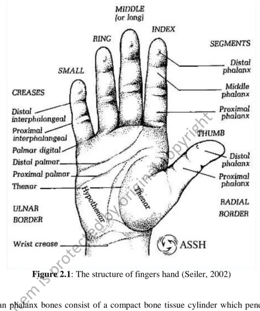
The average total of bones in adult human skeleton is about 206 bones, including phalanges bone of the human hand. Phalanges bone is a vital segment of the human body in helping human do many activities in their daily life. Therefore, the interest area in this project is on the phalanx bone of the human hand. The phalanx bone of human hand located at fingers. Generally, the fingers are formed by three phalanges; proximal, middle and distal phalanx. Figure 2.1 illustrated in details the structures of fingers hand.
© This
item is protecte d by
original
copyr
ight
7
Figure 2.1: The structure of fingers hand (Seiler, 2002)
Human phalanx bones consist of a compact bone tissue cylinder which penetrated by medullar cavity and inside the medullar cavity is the bone marrow. Then, at the end of the bones are built by a compact substance thin layer outside and a spongy mass inside.
This shows that human phalanx bone having a complex biological tissue. However, this type of bone can be modeled in the finite element analysis (Tarnita et al., 2005).
© This
item is protecte d by
original
copyr
ight
8 2.2 Fractures in bones
From 206 bones of the human skeleton, it can be classified into four groups; long bones, short bones, flat bones and irregular bones (Marieb, 2009). These bone classified is based on the shape of the bone.
Long bones relatively in long and slender shape. This type of bone usually situated in the arms, legs, thighs, palms, soles, fingers and toes. Then, short bones having cube- shaped which length and width is in same size. This short bone usually be found in the bone of the wrists (carpals) and bone of the ankle (tarsals).
Next are flat bones which having thin, flat surfaces and no marrow cavity structure.
However, this type of bone has the spongy bone sandwiched between layers of compact bone.Also, this type of bone can be searched in sternum, ribs, scapula, clavical and the bones which shape the roof of the skull (parietal, frontal, temporal and occipital).Last are irregular bones that have the complexity of shape, notched or with ridges. This irregular bone commonly located in the facial bones, pelvic bones, heel bone and mandible.
Therefore, this study focused on long bones fractured of human phalanx bone (finger bone). In addition, long bone having particular features such as hard and dense bone. These features had provided strength, structure and mobility. The structure and fractures in long bones will be discussed in details in next subtopic.
© This
item is protecte d by
original
copyr
ight
9 2.2.1 Fractures in Long Bones
Phalanges bones (finger bone) can be defined as long bone. These types of bones can be categorized into two regions; diaphysis and epiphysis. The structure of long bones that connect diaphysis with epiphysis is known as metaphysis. The long bone fractured, sometimes may occur at a portion of metaphysis or sometimes at the diaphysis.
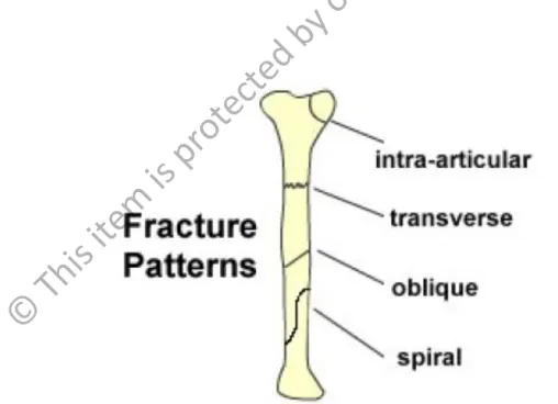
There are various types of fracture patterns occur at diaphysis such as intra- articular, transverse, oblique and spiral. In this study, transverse fractures were highlighted and these types of fractures usually related to angulate injuries or direct blows (Dent, 2008). Figure 2.2 illustrated in details the pattern of fracture diaphysis long bone.
Figure 2.2: The patterns of fracture diaphysis long bone (Dent, 2008)
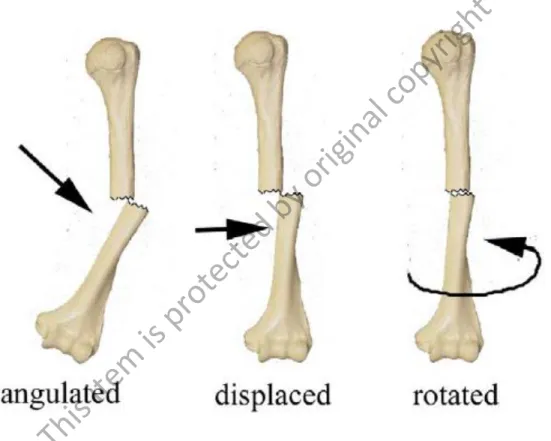
This transverse pattern can be related to the malalignment of phalanx bone.
Malalignment can be formed on phalanx bone in three conditions such as angulated, displaced and rotated. These types of malalignment conditions had been depicted in details
© This
item is protecte d by
original
copyr
ight
10
in Figure 2.3. Displaced condition had been focused on this study as this type of condition usually occur when the two bone ends are shifted on each other to different extents either in a forward/backwards direction or a sideways direction (Dent, 2008). Extensive works that had been done by other researchers on fractures in cortical bone will be discussed in next subtopics.
Figure 2.3: The types of malalignment condition on phalanx long bone (Dent, 2008).
2.2.2 Fractures in Human Cortical Bone
During the last decades, interaction of microcracks or fracture in human cortical bone attracts researchers’ attention. There were extensive works in developing the most accurate methods to be applied.
© This
item is protecte d by
original
copyr
ight
11
Najafi et al. (2009) accomplished a study that adopted Green's function to formulate a system of singular integral equations for the general microcracks in vicinity of the osteon.
Green's function is solution for the edge dislocations. This paper presented a two- dimensional micromechanical fiber-ceramic matrix composite material model that based on LEFM to evaluate the interaction between microcracks. This paper also studied the interaction between microcracks and the bone microstructure by understanding the effect of microstructural morphology and heterogeneity towards fracture behavior. The results show that when osteon is softer than interstitial tissue, the SIF is increased. For osteon is harder than interstitial tissue, the SIF is found to be decreased. It indicated that the SIF value depending on material mechanical properties. The SIF value also dependent on the configuration of microcracks either in the shape of stress amplification or in the shape of stress shielding.
Then, Shah et al. (2009) proposed two resin based dental composite materials;
microhybrid and nanofill in this study to investigate significant fracture and toughening mechanism. This study used an R-curve approach to characterize the fracture behavior of two dental composites. An experiment was conducted in this study including sample preparation, R curve testing, flexural strength testing, double notched experiment, and fracture and toughening mechanism. Fracture and toughening mechanism was characterize by Scanning Electron Microscope (SEM). Results showed that microhybrid composite having a 20% higher mean flexural strength compared to nanofill composite. The fracture resistance of both composite increases with crack extension over ~1 mm of crack length.The higher rising R-curve of the microhybrid dental composite indicated higher fracture toughness and higher flexural strength but less scatter in flexural strength. Two different extrinsic toughening mechanisms were identified; crack deflection and crack
© This
item is protecte d by
original
copyr
ight
12
bridging. Although Nanofill composite have the lower strength and toughness but this nanoparticle cluster is more effective at deflecting crack and imparting as the solid particles of the microhybrid.
Morais et al. (2010) conducted the Double Cantilever Beam (DCB) test in determining fracture toughness under pure mode I of cortical bone. A new data reduction scheme based on specimen compliance and crack equivalent concepts was introduced to overcome the difficulties in monitoring crack length of material. A cohesive zone model was used to simulate damage initiation and propagation, thus assessing the efficacy of the proposed testing method and data reduction scheme. Then, the DCB test was applied to evaluate the mode I fracture energy of hydrated and thermally dehydrated cortical bone tissue from the young bovine femur, in the tangential-longitudinal propagation system.
Results showed that the fracture process zone of dehydrated bone is much less that in hydrated tissue. The interaction between water and collagen matrix contributes significantly to fracture process and cortical bone fracture behavior. The DCB test and the proposed data reduction scheme on the bone fracture characterization under mode I loading l was demonstrated efficiently in this study.
While, Ural et al. (2011) focused on traumatic fractures of the human cortical bone.
The main objective of this study is to develop a computational approach based on cohesive finite element modelling in evaluating the effect of strain rate on both initiation and propagation toughness of human cortical bone. Two finite element modeling of compact tension was constructed, but in different dimensions. The first model includes the two dimensions (2-D) were simulated to evaluate the change in initiation and propagation fracture toughness with increasing strain rate. Second model involved three-dimensional (3- D) micro computed-tomography (µCT) which to assess the effect of porosity with
© This
item is protecte d by
original
copyr
ight