Review
Current Status of Cellulosic and Nanocellulosic Materials for Oil Spill Cleanup
Siegfried Fürtauer1,* , Mostafa Hassan2 , Ahmed Elsherbiny3, Shaimaa A. Gabal4 , Sherif Mehanny2 and Hatem Abushammala5
Citation: Fürtauer, S.; Hassan, M.;
Elsherbiny, A.; Gabal, S.A.; Mehanny, S.; Abushammala, H. Current Status of Cellulosic and Nanocellulosic Materials for Oil Spill Cleanup.
Polymers2021,13, 2739. https://
doi.org/10.3390/polym13162739
Academic Editor: Mirta I. Aranguren
Received: 18 July 2021 Accepted: 9 August 2021 Published: 16 August 2021
Publisher’s Note:MDPI stays neutral with regard to jurisdictional claims in published maps and institutional affil- iations.
Copyright: © 2021 by the authors.
Licensee MDPI, Basel, Switzerland.
This article is an open access article distributed under the terms and conditions of the Creative Commons Attribution (CC BY) license (https://
creativecommons.org/licenses/by/
4.0/).
1 Fraunhofer Institute for Process Engineering and Packaging IVV, 85354 Freising, Germany
2 Mechanical Design & Production Department, Faculty of Engineering, Cairo University, Cairo 12613, Egypt;
[email protected] (M.H.); [email protected] (S.M.)
3 Mechanical Engineering Department, University of Alberta, Edmonton, AB T6G 2R3, Canada;
4 Cellulose and Paper Department, National Research Centre, Dokki, Giza 12611, Egypt;
5 Environmental Health and Safety Program, College of Health Sciences, Abu Dhabi University, Abu Dhabi 51133, United Arab Emirates; [email protected]
* Correspondence: [email protected]; Tel.: +49-8161-491-526
Abstract:Recent developments in the application of lignocellulosic materials for oil spill removal are discussed in this review article. The types of lignocellulosic substrate material and their different chemical and physical modification strategies and basic preparation techniques are presented. The morphological features and the related separation mechanisms of the materials are summarized.
The material types were classified into 3D-materials such as hydrophobic and oleophobic sponges and aerogels, or 2D-materials such as membranes, fabrics, films, and meshes. It was found that, particularly for 3D-materials, there is a clear correlation between the material properties, mainly porosity and density, and their absorption performance. Furthermore, it was shown that nanocellu- losic precursors are not exclusively suitable to achieve competitive porosity and therefore absorption performance, but also bulk cellulose materials. This finding could lead to developments in cost- and energy-efficient production processes of future lignocellulosic oil spillage removal materials.
Keywords:cellulose; nanocellulose; oil spillage removal; aerogels; membranes; fabrics; chemical modification; separation; absorption
1. Introduction
1.1. Oil Spillage as an Environmental and Economic Challenge
Regularly, more than 35 billion gallons of petroleum oil are transported on ships per annum, and more than 10 million gallons are spilled in marine water, which poses severe jeopardy to aquatic habitats and causes catastrophic consequences for tourism, the economy, and human health [1,2].
In disastrous situations, as in the Gulf of Mexico in 2010, 184 million gallons were released into the ocean [3]. During the Gulf War in Kuwait (1991), 38 million gallons were emptied into Arab Gulf water [4]. Tanker spills like Atlantic Empress in 1978 near the West Indies constituted more than 8.9 million gallons, and the tanker ABT Summer in 1991 near Angola coast spilled more than 8 million gallons [5]. Less severely, natural oil seepages in the Gulf of Mexico exceed 2.1 million gallons, and 0.6 million gallons in California and Alaska offshore regions [6], with a best estimate of 18 million gallons around the globe per annum [7].
Oil inhibits sunlight from underwater photosynthetic activity, which directly disturbs the marine food chain. As a result of the fact that nutrients were set free through the bio- or photochemical degradation of oil, massive amounts of green algae were found, often
Polymers2021,13, 2739. https://doi.org/10.3390/polym13162739 https://www.mdpi.com/journal/polymers
Polymers2021,13, 2739 2 of 30
months or even years after the oil spills. Many creatures like mussels with plankton larvae have difficulty in re-settling as the algae then occupy the region. Coral reefs are susceptible to oil components and often die when oil spills occur near the reefs [5]. Oil droplets act as flypaper for many tiny organisms and entrap those organisms and kill them. Larger creatures may assimilate the oil when they go for their trapped microorganism prey, or they may inhale it and get it stuck on their gill membranes as they swim through the emulsion, which eventually intoxicates the human body (if fed on fish). If they are exposed to high concentrations, they will die; at much lower contamination levels, their physiologies will become impaired [8].
For being cost-effective, petroleum-based materials used for oil spillage clean-up have been widely used during the last few decades. However, their toxic effect in the marine environment—which is more harmful than the oil itself in some cases—has encouraged re- searchers and engineers to look for eco-friendly biodegradable alternatives which manifest almost zero toxicity and low cost.
1.2. Current Solutions and Materials Used for Oil Spill Clean-Up
Several solutions were implemented to solve oil spill (or seepage) problems. Those solutions can be used separately or jointly. Dave et al. [9] categorized solution methods into physical, chemical, biological, and in situ burning. Physical methods comprise con- tainment booms, skimming machines, and adsorbent materials. Chemical methods contain dispersants and solidifiers [9]. The biological method (bioremediation) is simply utilizing microbial activity to biodegrade (assimilate) heavy crude oil components into cell biomass and lighter constituents that are ecofriendly [10]. Thermal solution or in situ burning is also an efficient solution to eliminate oil spills; however, combustion wastes sometimes jeopardize aquatic life [11].
Inorganic natural adsorbents including clay, glass, and sand [12], or synthetic adsor- bent including polypropylene, polystyrene, and polyester foams exhibited good perfor- mance in oil spill removal [13]. However, lignocellulosic adsorbents still have substantial advantages compared to other materials particularly in terms of friendliness to the marine environment and light weight [14], in addition to other benefits that we will throw light upon in the next section. After conducting comparative analysis, mechanical processing and the application of dispersants followed by bioprocessing (bioremediation) is the most efficient procedure for marine oil spills [9].
1.3. Lignocelluloses Are Promising Alternatives
As per sorbent material functionality, lignocellulosic material is a promising candidate to carry out oil sorption tasks. Unlimited resource availability of this versatile biopolymer is roughly calculated to be 1.3×10¹⁰metric tons per annum [15,16], which directly reflects the low cost of developed lignocellulose solutions. The significantly lower specific weight (0.9–1.2 g cm−3) than sand and clay (3.2 and 1.7 g cm−3) facilitates the floatability of ligno- cellulose compared to other materials. Biodegradability is the key advantage in promoting lignocellulose material, composed mainly of cellulose, hemicellulose, and lignin [17], and does not have any toxic effect on marine or terrestrial environments. Cellulose-based materi- als can be versatile functionalized and modified to alter their properties, including porosity and hydrophobicity (oleophilicity) [18]. The porosity of the materials is a prerequisite to allow their use as adsorbers, to enable incorporation of oil spillages in their matrix. To increase the wettability of lignocellulosic materials, which are hydrophilic by nature, with oil and oil-like liquids, their surface can be chemically modified. Both material properties, porosity and hydrophobicity account for the overall adsorption performance of the ad- sorption materials. Due to emerging interest of lignocellulosic materials for oil adsorption, several reviews on their production and use have been published recently [2,17–24].
2. Introduction to Lignocellulose and Nanocellulose
Lignocelluloses, such as wood and plants, are composites of three polymers: cellulose, hemicelluloses, and lignin [25,26]. Cellulose is a semicrystalline linear homopolymer of glucose units connected via 1,4-β-glycosidic bonds. The degree of polymerization of cel- lulose can go up to 15 thousand units [19,27]. Hemicelluloses are amorphous branched heteropolymers of several sugars, including glucose, galactose, xylose, mannose, arabinose, glucu- and galacturonic acids. These sugars and sugar acids are connected using a variety of glycosidic bonds [28]. Lignin is an amorphous networked polyphenol of three phenyl propane units that differ on the degree of methoxylation at the meta position [29]. Lig- nocelluloses’ microstructure is very complex. Initially, around 36 cellulose chains bundle together to form elementary fibrils (diameter of 3–4 nm). These fibrils aggregate together to form sheets of microfibrils with a thickness of 10–30 nm, which are in turn embedded in an amorphous matrix of lignin and hemicelluloses [30]. The three polymers interlock together through lignin-carbohydrate complexes [31]. During pulping, the lignin-carbohydrate complexes are chemically disintegrated, the hemicelluloses and lignin are depolymerized, and cellulose is extracted in the form of 20–40µm pulp fibers. These fibers are directly used in the paper industry or dissolved and spun for the textile industry [32]. Recently, cellulose fibers have been chemically and mechanically disintegrated to form cellulose nanoparticles (NPs) or nanocellulose (NC) [33].
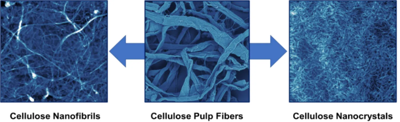
As shown in Figure1, there are two primary forms of nanocellulose: cellulose nanofib- rils (CNFs) and cellulose nanocrystals (CNCs). CNFs are semicrystalline spaghetti-like NPs with a thickness of 5–50 nm and a length of a few millimeters. They can be produced by the mechanical fibrillation of cellulose fibers using various equipment such as microflu- idizers, homogenizers, and micro grinders [34]. A synonymous term for CNF is also MFC (micro fibrillated cellulose). CNCs are highly crystalline rod-like NPs with a thickness of 5–20 nm and a length of a few hundred nanometers [35]. They are produced by the chemi- cal liberation of the cellulose crystallites from the pulp fibers using acid hydrolysis [36,37].
Sulfuric acid is mainly used, but other acids and chemical reagents have also been used [38].
If other mineral acids are used for hydrolysis, and larger particles are obtained, the result- ing material is microcrystalline cellulose (MCC). Both forms of nanocellulose have been widely explored in the last two decades due to their attractive properties. A special kind of nanocellulose, which falls under the CNFs umbrella, is bacterial nanocellulose (BNC).
Unlike other nanocelluloses, BNC is produced using a bottom-up approach by building up CNFs from simple sugars using bacteria [39].
2. Introduction to Lignocellulose and Nanocellulose
Lignocelluloses, such as wood and plants, are composites of three polymers: cellu- lose, hemicelluloses, and lignin [25,26]. Cellulose is a semicrystalline linear homopolymer of glucose units connected via 1,4-β-glycosidic bonds. The degree of polymerization of cellulose can go up to 15 thousand units [19,27]. Hemicelluloses are amorphous branched heteropolymers of several sugars, including glucose, galactose, xylose, mannose, arabi- nose, glucu- and galacturonic acids. These sugars and sugar acids are connected using a variety of glycosidic bonds [28]. Lignin is an amorphous networked polyphenol of three phenyl propane units that differ on the degree of methoxylation at the meta position [29].
Lignocelluloses’ microstructure is very complex. Initially, around 36 cellulose chains bun- dle together to form elementary fibrils (diameter of 3–4 nm). These fibrils aggregate to- gether to form sheets of microfibrils with a thickness of 10–30 nm, which are in turn em- bedded in an amorphous matrix of lignin and hemicelluloses [30]. The three polymers interlock together through lignin-carbohydrate complexes [31]. During pulping, the lig- nin-carbohydrate complexes are chemically disintegrated, the hemicelluloses and lignin are depolymerized, and cellulose is extracted in the form of 20–40 µm pulp fibers. These fibers are directly used in the paper industry or dissolved and spun for the textile industry [32]. Recently, cellulose fibers have been chemically and mechanically disintegrated to form cellulose nanoparticles (NPs) or nanocellulose (NC) [33].
As shown in Figure 1, there are two primary forms of nanocellulose: cellulose nano- fibrils (CNFs) and cellulose nanocrystals (CNCs). CNFs are semicrystalline spaghetti-like NPs with a thickness of 5–50 nm and a length of a few millimeters. They can be produced by the mechanical fibrillation of cellulose fibers using various equipment such as micro- fluidizers, homogenizers, and micro grinders [34]. A synonymous term for CNF is also MFC (micro fibrillated cellulose). CNCs are highly crystalline rod-like NPs with a thick- ness of 5–20 nm and a length of a few hundred nanometers [35]. They are produced by the chemical liberation of the cellulose crystallites from the pulp fibers using acid hydrol- ysis [36,37]. Sulfuric acid is mainly used, but other acids and chemical reagents have also been used [38]. If other mineral acids are used for hydrolysis, and larger particles are ob- tained, the resulting material is microcrystalline cellulose (MCC). Both forms of nanocel- lulose have been widely explored in the last two decades due to their attractive properties.
A special kind of nanocellulose, which falls under the CNFs umbrella, is bacterial nano- cellulose (BNC). Unlike other nanocelluloses, BNC is produced using a bottom-up ap- proach by building up CNFs from simple sugars using bacteria [39].
Figure 1. From cellulose pulp fibers to CNFs and CNCs. The photo of the cellulose pulp fibers was obtained using a scanning electron microscope (500 × 500 µm), while those of CNFs and CNCs are atomic force microscopy images (5 × 5 µm).
Nanocelluloses have inherited both the properties of cellulose, such as low density, high mechanical properties, biodegradability, and biocompatibility, and the properties of NPs such as specific surface area and self-assembly [40]. However, nanocelluloses are Figure 1.From cellulose pulp fibers to CNFs and CNCs. The photo of the cellulose pulp fibers was obtained using a scanning electron microscope (500×500µm), while those of CNFs and CNCs are atomic force microscopy images (5×5µm).
Nanocelluloses have inherited both the properties of cellulose, such as low density, high mechanical properties, biodegradability, and biocompatibility, and the properties of NPs such as specific surface area and self-assembly [40]. However, nanocelluloses are most famous for the abundance of hydroxyl groups on their surfaces, opening the doors
Polymers2021,13, 2739 4 of 30
for unlimited possibilities to functionalize them [41]. A wide range of chemical moieties has been placed on the surface of nanocelluloses, including simple molecules and poly- mers [42]. Due to these exciting properties, nanocelluloses have shown great potential in a wide range of applications [43], including tissue engineering [44], automotive and aerospace industries [45], pharmaceutical formulation [46], water filtration [47], flexible electronics [48], packaging materials [49], lightweight composites and construction mate- rials [50,51] and needless to say oil spillage clean up [52,53]. This has also led to massive interest from academia and industry. More than 3000 articles about nanocellulose were published in 2020 compared to around 200 in 2009. This has also led to the establishment of tens of nanocellulose manufacturing facilities worldwide [42].
3. Surface Modification of Cellulose and Nanocellulose
Cellulose and nanocellulose are highly hydrophilic materials due to their chemical nature. Hydroxyl groups exposed to the surface of cellulose fibrils and along the cellulose molecule backbone form intermolecular hydrogen bonds but also interfere with water molecules. The wettability of a surface with any solvent is determined via contact angle measurement of a sessile drop of respective solvent—in the case of water, this is defined as the water contact angle (WCA). The higher the WCA, the more hydrophobic is the wetted surface. The theoretical limits are WCA = 0◦(full wettability with water) and WCA = 180◦ (no wettability with water = super-hydrophobic). In practice, materials with a WCA above 90◦ are related to hydrophobic materials, such as those with WCA above 150◦ which are considered super-hydrophobic. For increasing the hydrophobicity of cellulosic and nanocellulosic materials, the surface has to be chemically or physically modified. In the following, some methods are summarized and compared.
3.1. Silylation
Silylation or silanization is a ubiquitous, effective, and easy method for surface hy- drophobization via grafting. Here the hydroxyl groups of cellulose undergo a condensation reaction with a wide range of silanes. Those silanes are generally alkoxy- (methoxy-, ethoxy-) or chlorosilanes, which have additional organic functionality, representing the hydrophobic part of the molecule (see Figure2; nomenclature for silanes throughout this review: “hydrophobic chain type” + “number of cleavage groups” + “cleavage group type”-silane, e.g., methyltrichlorosilane, abbreviation MTCS).
Polymers 2021, 13, x FOR PEER REVIEW 4 of 31
most famous for the abundance of hydroxyl groups on their surfaces, opening the doors for unlimited possibilities to functionalize them [41]. A wide range of chemical moieties has been placed on the surface of nanocelluloses, including simple molecules and poly- mers [42]. Due to these exciting properties, nanocelluloses have shown great potential in a wide range of applications [43], including tissue engineering [44], automotive and aero- space industries [45], pharmaceutical formulation [46], water filtration [47], flexible elec- tronics [48], packaging materials [49], lightweight composites and construction materials [50,51] and needless to say oil spillage clean up [52,53]. This has also led to massive interest from academia and industry. More than 3000 articles about nanocellulose were published in 2020 compared to around 200 in 2009. This has also led to the establishment of tens of nanocellulose manufacturing facilities worldwide [42].
3. Surface Modification of Cellulose and Nanocellulose
Cellulose and nanocellulose are highly hydrophilic materials due to their chemical nature. Hydroxyl groups exposed to the surface of cellulose fibrils and along the cellulose molecule backbone form intermolecular hydrogen bonds but also interfere with water molecules. The wettability of a surface with any solvent is determined via contact angle measurement of a sessile drop of respective solvent—in the case of water, this is defined as the water contact angle (WCA). The higher the WCA, the more hydrophobic is the wet- ted surface. The theoretical limits are WCA = 0° (full wettability with water) and WCA = 180° (no wettability with water = super-hydrophobic). In practice, materials with a WCA above 90° are related to hydrophobic materials, such as those with WCA above 150° which are considered super-hydrophobic. For increasing the hydrophobicity of cellulosic and nanocellulosic materials, the surface has to be chemically or physically modified. In the following, some methods are summarized and compared.
3.1. Silylation
Silylation or silanization is a ubiquitous, effective, and easy method for surface hy- drophobization via grafting. Here the hydroxyl groups of cellulose undergo a condensa- tion reaction with a wide range of silanes. Those silanes are generally alkoxy- (methoxy-, ethoxy-) or chlorosilanes, which have additional organic functionality, representing the hydrophobic part of the molecule (see Figure 2; nomenclature for silanes throughout this review: “hydrophobic chain type” + “number of cleavage groups” + “cleavage group type”-silane, e.g., methyltrichlorosilane, abbreviation MTCS).
Figure 2. Typical functional groups for hydrophobic silanes.
The alkoxy- or chloro-functional groups are cleavage groups, forming either the re- spective free alcohols such as methanol or ethanol, or hydrochloric acid during the con- densation reaction. The condensation reaction can be initiated thermally, e.g., via chemical vapor deposition of a chlorosilane onto the surface of the dry aerogel, at temperatures of 70–100 °C. Another possibility for grafting is the hydrolysis of alkoxysilanes with diluted acids and mixing with the cellulose matrix before freeze-drying or impregnating the ready-made aerogel and curing at temperatures up to 120 °C. The hydrophobicity de- pends on the grafting yield, which is related to the process parameters and the type of organic modification of the silane. For instance, long-chain alkyl residues (C16 [54–58],
Figure 2.Typical functional groups for hydrophobic silanes.
The alkoxy- or chloro-functional groups are cleavage groups, forming either the respec- tive free alcohols such as methanol or ethanol, or hydrochloric acid during the condensation reaction. The condensation reaction can be initiated thermally, e.g., via chemical vapor de- position of a chlorosilane onto the surface of the dry aerogel, at temperatures of 70–100◦C.
Another possibility for grafting is the hydrolysis of alkoxysilanes with diluted acids and mixing with the cellulose matrix before freeze-drying or impregnating the ready-made aerogel and curing at temperatures up to 120◦C. The hydrophobicity depends on the grafting yield, which is related to the process parameters and the type of organic modifi- cation of the silane. For instance, long-chain alkyl residues (C16 [54–58], C18 [59]) show also higher hydrophobicity (WCA = 139–159◦) as in short-chain alkyl residues (C8 [60,61], C12 [62]; WCA = 120–150◦). However, very high WCAs can be achieved by grafting with
methyl-substituted organosilanes (methyltrimethoxysilane, MTMS), probably due to a sterically favorable condensation reaction (WCA = 168.4◦[63]). Also, vinyltrimethoxysilane (VTMS) is used [64]. Other silane-based surface hydrophobization agents contain fluori- nated alkyls (perfluorooctyltriethoxysilane, PFOTES [65] and perfluorodecyltriethoxysilane, PFDTES [66]); however, the WCAs are similar to those achieved by non-fluorinated silanes (146 and 157◦, respectively).
3.2. Carbon
Hydrophobic modification in the form of carbon has become increasingly important, since this is considered as a green alternative to silanization. Typically, organic matrices are pyrolyzed under the exclusion of oxygen (e.g., 800◦C under N2[67] or at even lower temperatures, 350◦C [68]), and/or mixed with graphene oxide (GO), which could also be reduced to graphene (e.g., 200◦C under H2[69,70]). In other cases, graphite flakes [71]
or carbon nanotubes (CNTs) [72] are directly mixed with the cellulosic matrices before freeze-drying. The hydrophobicity (WCA) of carbonized surfaces is lower than that of silylated ones (WCA = 123–141◦ [67,72]), but still in a range to have effective wetting with oils and oil-like liquids. The adsorption capacities of such carbon-based adsorption materials can be quite high compared to those solely produced by freeze drying. However, this is more a function of the precursor used than the processing route, since adsorption capacities can vary tremendously [67,69,71,72].
3.3. Other Methods
Further strategies to increase hydrophobicity is the incorporation of inorganics (TiO2
layers [73] or NPs [74,75]) Cu-NPs [76], Ag-NPs [77], Al2O3-NPs, surfactants (cetyltrimethy- lammonium chloride, CTAC [78], SDS [79], stearic acid (SA) [71,80], oleic acid [56,81], epoxidized soybean oil (ESBO) [82]) or other types of grafting molecules (polydopamine PDA and octadecylamine ODA [83,84], poly(N,N-dimethylamino-2-ethyl methacrylate) PDMAEMA [85], polythiophene [86], acid chlorides [87,88], by carboxymethylation [60] or polymers [89,90]). As with the materials formed by carbonization, there cannot be a general rule deduced to state which hydrophobization method is the best in order to achieve the most beneficial material properties. Many different factors, like precursor type and origin, processing method and processing parameters, and even testing setup, influence the evaluation of the adsorption material performance.
4. Processing of Cellulose and Nanocellulose to 3D and 2D Materials
Cellulose and its derivatives, by nature, are among the perfect candidates to constitute aerogel textures. The high content of hydroxyl groups in cellulose chains increases the like- lihood of linking with other chains to form a stable 3D gel texture, which is already stable without using a chemical crosslinker [91–93]. However, concerning improved mechanical stability, shape recovery, and insolubility, chemical crosslinkers could be beneficial. In the following lines, we will throw light on aerogel fabrication methods.
4.1. Sol-Gel Preparation
In a sol, colloidal cellulose particles with sizes ranging from 1 nm to 1000 nm are dispersed in a liquid. A gel consists of a solid, spongy 3D network whose clusters are filled with another liquid [94]. The sol-gel reaction is the process in which material converts from liquid sol phase to solid gel phase (gelation). The sol-gel reaction is the most decisive step in creating a porous 3D web structure in an aerogel. In other words, a sol-gel reaction is a reaction of fixing molecules in the same position via physical or chemical links after moving freely in liquid sol [95,96].
As a result of complex intermolecular and intramolecular hydrogen bond networking in cellulose macromolecules, cellulose is not soluble in water and shows amphiphilic nature, but can be dissolved in various solvents and be regenerated afterwards. LiCl/dimethylacetamide (DMAc) [97], LiCl/DMSO [98], alkali/water/urea [82,99–102] or thiourea [74,103], ionic liq-
Polymers2021,13, 2739 6 of 30
uids (IL), e.g., 1-allyl-3-methylimidazolium chloride (AmimCl) [59,104–106] and deep-eutectic solvents (DES), e.g., choline-chloride/urea [107]) are most famous cellulose dissolution systems. Cellulose solvents substantially influence regenerated cellulose properties, regard- less of the fabricated material being membrane, hydrogel, or aerogel. After a homogenous solution is maintained, new cellulose chains are regenerated (coagulated) using several coagulants depending on the solvent type; for instance, the NaOH/urea system is regener- ated by dilute H2SO4, the DMAc system is regenerated by ethyl acetate, and some other systems do not need anything but water as a coagulant. A wide variety of membranes, either by casting or spinning, can be fabricated by dissolution/regeneration reaction [108].
4.2. Stabilization of the Gel 4.2.1. Chemical Crosslinkers
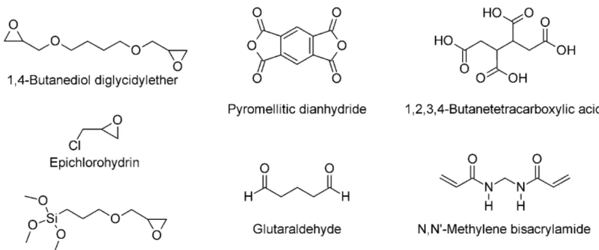
Chemical crosslinkers covalently crosslink the cellulose backbone of the aerogels to ensure higher mechanical stability, better shape recovery, and less solubility. They are usually mixed with the cellulose sol and activated via heat treatment after the aerogel formation. In many cases, the hydroxyl group of the cellulose is a target for crosslink- ing (typical examples for chemical crosslinkers see Figure 3). Ethers are formed with homo-biofunctional crosslinkers such as 1,4-butanediol diglycidylether (BDE) [82,109], glutaraldehyde (GA) [106,110–112], polymethylsilsesquioxane (PMSQ) [113], or hetero- bifunctional crosslinkers, such as (3-glycidyloxypropyl)trimethoxysilane (GPTMS), which undergoes subsequently self-condensation with its silanol-group [85], or epichlorohy- drin (ECH) [57,77,114]. Oxidation of the cellulose pyrane ring with NaIO4results in a highly reactive dialdehyde, which could be crosslinked with chitosan to form the Schiff base [101]. The dialdehyde functionality could also react with hydrazine-functionalized CNCs, originating from carboxylated CNCs via carbodiimide chemistry, forming a hy- drazone cross-linkage [115]. Ester linkages can be formed between the hydroxyl group of cellulose and pyromellitic dianhydride (PMDA) [61] or butanetetracarboxylic acid (BTCA) [116,117]. The reactivity of cellulose acetoacetate (CAA) with primary amine groups of 3-aminopropyltriethoxysilane (APTES) [118], or the reaction of the azetidinium groups of polyamideamine-ECH (PAE) and carboxyl groups of CNFs [117,119], was used to form other types of covalent linkage. Another common crosslinker isN,N0-methylene bisacrylamide (MBA) [100,102], which forms urea-like linkages between hydroxyl groups of different cellulose molecules. Grafted VTMO (vinyl-trimethoxysilane) on nanocellulose surfaces can undergo radical polymerization with azobis(isobutyronitrile) (AIBN) [120].
Polymers 2021, 13, x FOR PEER REVIEW 6 of 31
As a result of complex intermolecular and intramolecular hydrogen bond network- ing in cellulose macromolecules, cellulose is not soluble in water and shows amphiphilic nature, but can be dissolved in various solvents and be regenerated afterwards. LiCl/di- methylacetamide (DMAc) [97], LiCl/DMSO [98], alkali/water/urea [82,99–102] or thiourea [74,103], ionic liquids (IL), e.g., 1-allyl-3-methylimidazolium chloride (AmimCl) [59,104–
106] and deep-eutectic solvents (DES), e.g., choline-chloride/urea [107]) are most famous cellulose dissolution systems. Cellulose solvents substantially influence regenerated cel- lulose properties, regardless of the fabricated material being membrane, hydrogel, or aer- ogel. After a homogenous solution is maintained, new cellulose chains are regenerated (coagulated) using several coagulants depending on the solvent type; for instance, the NaOH/urea system is regenerated by dilute H
2SO
4, the DMAc system is regenerated by ethyl acetate, and some other systems do not need anything but water as a coagulant. A wide variety of membranes, either by casting or spinning, can be fabricated by dissolu- tion/regeneration reaction [108].
4.2. Stabilization of the Gel
4.2.1. Chemical Crosslinkers
Chemical crosslinkers covalently crosslink the cellulose backbone of the aerogels to ensure higher mechanical stability, better shape recovery, and less solubility. They are usually mixed with the cellulose sol and activated via heat treatment after the aerogel formation. In many cases, the hydroxyl group of the cellulose is a target for crosslinking (typical examples for chemical crosslinkers see Figure 3). Ethers are formed with homo- biofunctional crosslinkers such as 1,4-butanediol diglycidylether (BDE) [82,109], glutaral- dehyde (GA) [106,110–112], polymethylsilsesquioxane (PMSQ) [113], or hetero-bifunc- tional crosslinkers, such as (3-glycidyloxypropyl)trimethoxysilane (GPTMS), which un- dergoes subsequently self-condensation with its silanol-group [85], or epichlorohydrin (ECH) [57,77,114]. Oxidation of the cellulose pyrane ring with NaIO
4results in a highly reactive dialdehyde, which could be crosslinked with chitosan to form the Schiff base [101]. The dialdehyde functionality could also react with hydrazine-functionalized CNCs, originating from carboxylated CNCs via carbodiimide chemistry, forming a hydrazone cross-linkage [115]. Ester linkages can be formed between the hydroxyl group of cellulose and pyromellitic dianhydride (PMDA) [61] or butanetetracarboxylic acid (BTCA) [116,117]. The reactivity of cellulose acetoacetate (CAA) with primary amine groups of 3- aminopropyltriethoxysilane (APTES) [118], or the reaction of the azetidinium groups of polyamideamine-ECH (PAE) and carboxyl groups of CNFs [117,119], was used to form other types of covalent linkage. Another common crosslinker is N,N′-methylene bisacryla- mide (MBA) [100,102], which forms urea-like linkages between hydroxyl groups of differ- ent cellulose molecules. Grafted VTMO (vinyl-trimethoxysilane) on nanocellulose sur- faces can undergo radical polymerization with azobis(isobutyronitrile) (AIBN) [120].
Figure 3.Typical molecules for cellulose crosslinking.
4.2.2. Polymeric Matrix Stabilizers
For increasing the stiffness and hydrophobicity of formed aerogels, polymers can be used as matrix stabilizers. The main difference between chemical crosslinkers and polymers as matrix stabilizers is that polymers do not necessarily form covalent bonds with the cellulosic matrix, but are mainly physically adsorbed and interact by weaker intermolecular bonds. However, the stabilization of the cellulosic matrices by polymer networks is not less effective than by covalent crosslinkers, since the degree of formation of new covalent bonds with the cellulose is highly dependent on the accessibility of linking groups, which may vary between substrates, depending on their origin, morphology and pretreatment. Some examples for polymer-stabilized cellulosic materials are given as follows: wood fines coated with a poly(methyl methacrylate) (PMMA)-solution in tetrahydrofuran (THF) [121] or polyethyleneimine (PEI) on GPTMS stabilized aerogel [85]
are examples of polymer coatings from solutions. Polyvinyl alcohol (PVOH), but also ethylene vinyl alcohol (EVOH) are widely used matrix polymers for cellulosic aerogels since they can be thermally cured and can, due to their chemical similarity to cellulose, be crosslinked with the same crosslinker types [89,111,114,116]. Also, natural polymers such as chitosan are used [70,122]. Matrix polymer coatings can also be formed in-situ, such as polyhemiaminals (PHAs) [90], polydopamine/PEI [58], or polymerization resins of methacrylates (styrene-butyl acrylate SBA, ethylene dimethacrylate EDMA) [123]. Also, metal oxide frameworks (MOFs) [124] or inorganic clay species [125], which are not strictly polymeric but also do not covalently crosslink with cellulose, can stabilize the final aerogel.
4.3. Drying Processes for Aerogel Formation 4.3.1. Supercritical CO2Drying
Since CO2has a suitable critical point (304 K, 7.4 MPa) in addition to low cost and high safety, it is a kind of fluid that is commonly used for drying cellulose aerogels [74].
Supercritical drying comprises two successive stages; firstly, supercritical carbon dioxide (scCO2) diffuse into the gel pores substituting solvent molecules that will be spilled out of the gel structure; secondly, the gel texture will be dominated by supercritical fluid which exhibit neither surface tension nor capillary action behavior; hence, no structure shrinkage will take place. In non-supercritical drying, shrinkage happens by climbing up liquid through capillary channels, leading to inward forces from the channel walls towards the channel axis, which shrinks the whole texture and induces cracks [126,127].
4.3.2. Vacuum Freeze Drying
Prior to the freeze-drying process, the gel is first cooled below the freezing point of the gel liquid (usually water) afterward; the liquid is eliminated by sublimation (transformation of solid to gas directly, without passing through the liquid phase), which is a major factor in preventing shrinkage texture collapse. Temperature and cooling rate play a drastic role in the crystallization and growth behavior of the newly formed structure, including pore size and distribution [105,128]. For cellulose aerogels, freeze-drying was found to be a more efficient way than scCO2. Moreover, rapid cooling to cellulose gels inhibits potential agglomeration of cellulose chains, yielding more coherent structure, which is why treatment with liquid nitrogen is so favored before freeze-drying of cellulose [129]. In some cases, bidirectional freeze-drying is favorable to achieve hierarchical structures with high diffusivity and outstanding mechanical properties [62,130].
4.4. Alternative Preparation Methods
In this section a brief overview about alternative preparation methods is given, which cannot be attributed to the previous techniques, but still play a role for preparation of porous lignocellulosic materials. In the easiest case, porous cellulose materials can be found in nature, like cellulose sponges typically used as kitchen wipes, but those have comparable low-specific surfaces [86]. The incorporation of chemical foaming agents (e.g., p-toluenesulfonyl hydrazide) or physical foaming agents (e.g., Na2SO4) into cellulose
Polymers2021,13, 2739 8 of 30
solutions were reported for the preparation of aerogels [59]. Electrospinning can be used to produce fibers from a dissolved polymer solution or melt. As cellulose acetate (CA) can be processed into deposited fibers with a very high specific surface [58,89], it could either be used directly as absorber material or regenerated to cellulose by deacetylation with NaOH [89]. Also, hydrothermal treatment is another method to produce heterogenous aerogels in a one-pot-approach, e.g., for the system cellulose/GO/silica/PFDTES [66].
5. Performance of Lignocellulosic Materials for Oil Spill Cleanup 5.1. Three-Dimensional (3D) Materials: Aerogels and Foams
In this review, 3D materials are defined as materials, which obtain their oil spillage cleanup properties via their volume dimension. They are typically aerogels, foams, or spongy materials and can perform either as absorbers or membranes/filters.
5.1.1. Separation Mechanism
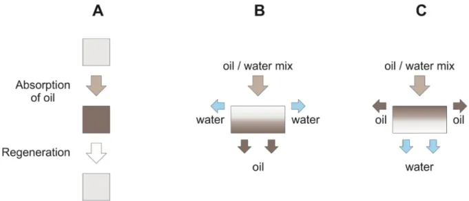
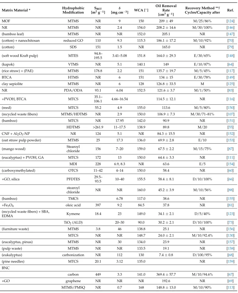
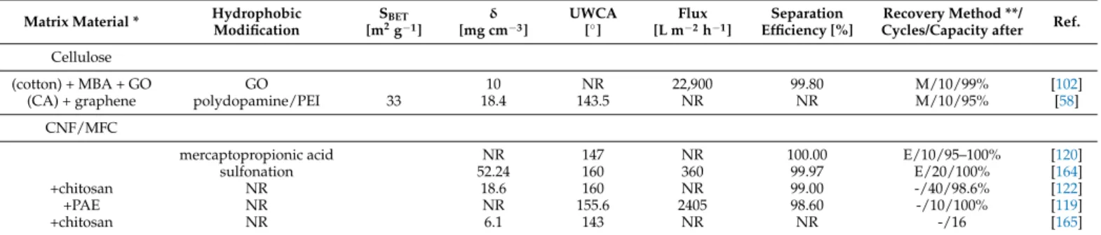
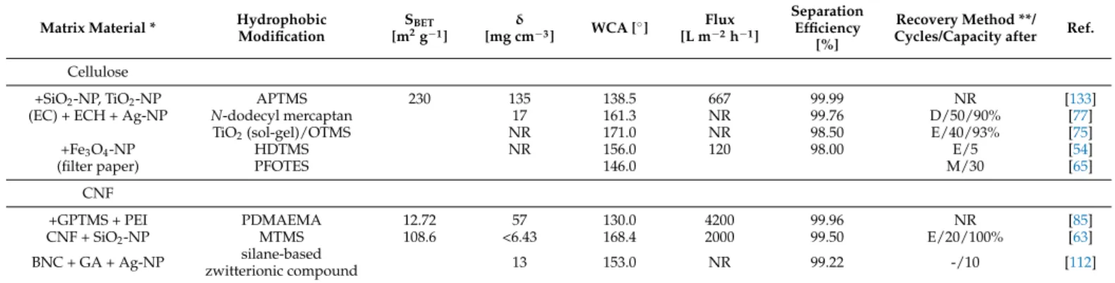
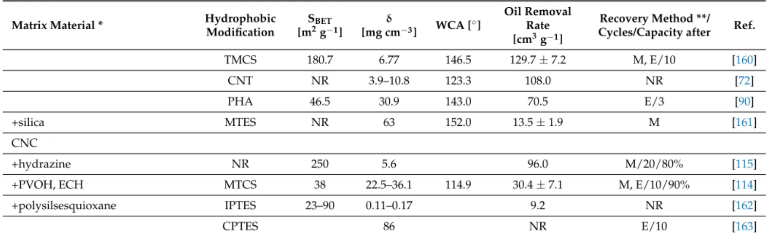
Depending on the surface modification, hydrophilic and hydrophobic 3D materials are reported. Hydrophobic 3D materials are typically absorber -like, which means that the oil is entirely absorbed by the porous material and has to be recovered after cleanup (see Table1[2–9,12–18,20–25,27–78,131,132], and Figure4A). Alternatively, some hydrophobic 3D materials are also used as filters—here the hydrophobic surface repels the aqueous phase—whereby the oil phase passes through the porous material and is so separated (see Table2, [54,63,65,75,77,85,133], and Figure4B). By contrast, hydrophilic 3D materials, which are used as separating membranes, retain the oil phase and let the aqueous phase pass (see Table3, [58,102,119], and Figure4C). For those hydrophilic materials, for practical reasons, the oil contact angle is expressed as underwater contact angle (UWCA) of the oil droplet in water instead of the WCA. The comparison of different separation mechanisms is depicted in Figure4A–C.
Polymers 2021, 13, x FOR PEER REVIEW 8 of 31
found in nature, like cellulose sponges typically used as kitchen wipes, but those have comparable low-specific surfaces [86]. The incorporation of chemical foaming agents (e.g., p-toluenesulfonyl hydrazide) or physical foaming agents (e.g., Na2SO4) into cellulose so- lutions were reported for the preparation of aerogels [59]. Electrospinning can be used to produce fibers from a dissolved polymer solution or melt. As cellulose acetate (CA) can be processed into deposited fibers with a very high specific surface [58,89], it could either be used directly as absorber material or regenerated to cellulose by deacetylation with NaOH [89]. Also, hydrothermal treatment is another method to produce heterogenous aerogels in a one-pot-approach, e.g., for the system cellulose/GO/silica/PFDTES [66].
5. Performance of Lignocellulosic Materials for Oil Spill Cleanup 5.1. Three-Dimensional (3D) Materials: Aerogels and Foams
In this review, 3D materials are defined as materials, which obtain their oil spillage cleanup properties via their volume dimension. They are typically aerogels, foams, or spongy materials and can perform either as absorbers or membranes/filters.
5.1.1. Separation Mechanism
Depending on the surface modification, hydrophilic and hydrophobic 3D materials are reported. Hydrophobic 3D materials are typically absorber -like, which means that the oil is entirely absorbed by the porous material and has to be recovered after cleanup (see Table 1 [2–9,12–18,20–25,27–78,131,132], and Figure 4A). Alternatively, some hydrophobic 3D materials are also used as filters—here the hydrophobic surface repels the aqueous phase—whereby the oil phase passes through the porous material and is so separated (see Table 2, [54,63,65,75,77,85,133], and Figure 4B). By contrast, hydrophilic 3D materials, which are used as separating membranes, retain the oil phase and let the aqueous phase pass (see Table 3, [58,102,119], and Figure 4C). For those hydrophilic materials, for practi- cal reasons, the oil contact angle is expressed as underwater contact angle (UWCA) of the oil droplet in water instead of the WCA. The comparison of different separation mecha- nisms is depicted in Figure 4A–C.
Figure 4. Separation mechanism of 3D materials: (A) absorber type; (B) hydrophobic filters; (C) hydrophilic filters.
5.1.2. Material Performance
Comparability of Different Materials
The material performance for 3D materials can be expressed either as (a) maximum absorption capacity regarding oil or non-polar solvents, in the case of static absorption processes, or (b) (flux-dependent) separation efficiencies, expressed as the ratio of removal Figure 4.Separation mechanism of 3D materials: (A) absorber type; (B) hydrophobic filters; (C) hydrophilic filters.
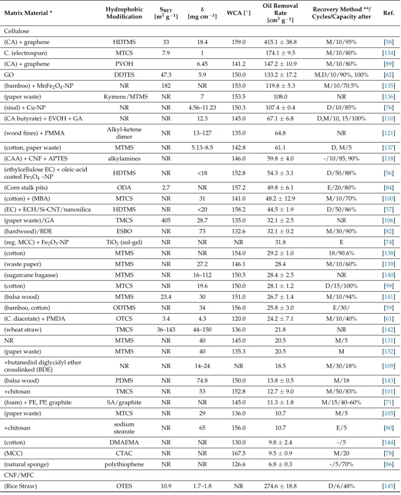
Table 1.Hydrophobic aerogels used for oil absorption.
Matrix Material * Hydrophobic
Modification
SBET
[m2g−1]
δ
[mg cm−3] WCA [◦]
Oil Removal Rate [cm3g−1]
Recovery Method **/
Cycles/Capacity after Ref.
Cellulose
(CA) + graphene HDTMS 33 18.4 159.0 415.1±38.8 M/10/95% [58]
C. (electrospun) MTCS 7.9 1 174.1±9.5 M/10/80% [134]
(CA) + graphene PVOH 6.45 141.2 147.2±10.9 M/10/80% [89]
GO DDTES 47.3 5.9 150.0 133.2±17.2 M,D/10/90%, 100% [62]
(bamboo) + MnFe2O4-NP NR 182 NR 153.0 119.8±5.3 M/10/70.5% [135]
(paper waste) Kymene/MTMS NR 7 153.5 108.0 NR [136]
(sisal) + Cu-NP NR NR 4.56–11.23 150.3 107.4±0.4 D/10/85% [76]
(CA butyrate) + EVOH + GA NR NR 12.3 145.0 67.1±6.8 D,M/10, 15/100% [110]
(wood fines) + PMMA Alkyl-ketene
dimer NR 13–127 135.0 64.8 NR [121]
(cotton, paper waste) MTMS NR 5.13–8.5 142.8 61.1 D, M/5 [137]
(CAA) + CNF + APTES alkylamines NR 146.0 59.8±4.0 -/10/85, 90% [118]
(ethylcellulose EC) + oleic-acid
coated Fe3O4–NP HDTMS NR <18 152.8 54.3±3.1 D/50/88% [56]
(Corn stalk pits) ODA 2.7 NR 157.2 49.8±6.1 E/20/80% [84]
(cotton) + (MBA) MTCS NR 31 141.0 48.2±12.9 M/10/70% [100]
(EC) + ECH/Si-CNT/nanosilica HDTMS NR <20 158.2 44.5±1.9 D/50/86% [57]
(paper waste)/GA TMCS 405 28.7 135.0 32.1±2.5 NR [106]
(hardwood)/BDE ESBO NR 73 132.6 32.1±0.2 M/30/90% [82]
(reg. MCC) + Fe2O3-NP TiO2(sol-gel) NR NR NR 31.8 E [74]
(cotton) MTMS NR NR 154.0 29.2±1.0 18/90.6% [138]
(waste paper) MTMS NR 27.2 146.1 28.4 M/10/60% [139]
(sugarcane bagasse) MTMS NR 16–112 150.5 28.4±2.5 NR [140]
(cotton) MTCS NR 19.6 150.0 28.1±1.2 D/15/100% [99]
(balsa wood) MTMS 23.4 30 151.0 26.7±1.4 M/10/94% [141]
(bamboo, cotton) ODTMS NR 34 156.0 25.8±3.0 E/30/ [59]
(C. diacetate) + PMDA OTCS 3.4 4.3 120.0 24.2±7.1 M/10/40% [61]
(wheat straw) TMCS 36–143 44–150 136.0 21.8 NR [142]
NR MTMS NR 40 145.0 20.5 M/5 [131]
(paper waste) MTMS NR 40 135.3 20.5 M [132]
+butanediol diglycidyl ether
crosslinked (BDE) NR NR 14–24 NR 18.5 M/30/18% [109]
(balsa wood) PDMS NR 74.8 150.0 13.8±0.5 M/18 [143]
+chitosan TMCS NR 53 152.8 12.7±9.0 M/50/83% [101]
(foam) + PE, PP, graphite SA/graphite NR NR 145.0 11.3±1.8 M/15/40–60% [71]
(paper waste) MTCS NR 29 136.0 10.7 M/5 [105]
+chitosan sodium
stearate NR 65 156.0 10.7 E/5 [80]
(cotton) DMAEMA NR NR 130.0 9.8±2.4 -/5 [144]
(MCC) CTAC NR NR 167.5 9.5±0.9 M/20 [78]
(natural sponge) polythiophene NR NR 126.6 6.8±0.3 -/5/70% [86]
CNF/MFC
(Rice Straw) OTES 10.9 1.7–1.8 NR 274.6±18.8 D/6/48% [145]
Polymers2021,13, 2739 10 of 30
Table 1.Cont.
Matrix Material * Hydrophobic
Modification
SBET
[m2g−1]
δ
[mg cm−3] WCA [◦]
Oil Removal Rate [cm3g−1]
Recovery Method **/
Cycles/Capacity after Ref.
MOF MTMS NR 9 150 209±49 M/25/86% [124]
NR MTMS NR 2.4 154.0 208.2±14.6 M/30/100% [146]
(bamboo leaf) MTMS NR NR 152.0 205.1 NR [147]
(cotton) + nanochitosan reduced GO 110 9.3 115.3 186.1±17.2 M/10/92% [70]
(cotton) SDS 151 1.5 NR 165.0 NR [79]
(soft wood Kraft pulp) MTES 94.8–
195.5 3.41–5.08 151.8 164.0±29.3 E/30/65% [148]
(kapok) VTMS NR 5.1 140.1 149 E/10/87% [64]
(rice straw) + (PAE) MTMS 178.8 2.2 151 135.7±19.7 M/5/45% [117]
BTCA HTMS NR 6 151 134±15 E/30/78% [149]
clay sepiolite MTMS NR 6 128 126.8±33.5 M [125]
NR PDA/ODA 93.1 6.04 152.5 121.6±3.7 M/1/50% [83]
+PVOH, BTCA MTCS 35.1–
106.1 4.66–16.54 114.5±12.1 NR [116]
(reed) MTCS 55.2 4.9 155.0 113.6 M/5/80% [150]
(recycled waste fibers) MTMS/HDTMS NR 2.9 150.0 106.9±7.3 M/30/71–81% [107]
(bamboo) MTCS NR 17.95 142.0 90.9 NR [151]
HDTMS >261.9 11–17.5 138.9 89.8 M/20 [55]
CNF + Al2O3-NP NR 124 5.1 NR 84.3±15.5 NR [152]
(oat straw pulp powder) MTMS 25 17.3 136.0 69.9±2.8 E/10 [153]
(mango wood) Stearoyl
chloride 156 7–20 159.0 67.5±2.2 M/15/75% [87]
(eucalyptus) + PVOH, GA MTCS 172 13 150.0 64.4±3.3 NR [111]
MDI 228 6.9, 8.3 NR 63.6 E/5 [154]
(carboxymethylated) OTCS 11–42 4–14 150.0 58.4 NR [60]
+GO, silica PFDTES 29.5–
93.5 10–40 155.5 58.4±8.1 D/10/100% [66]
stearoyl
chloride NR NR 160.0 45.2±3.9 M/10/56% [88]
(bamboo) TMCS 6.78 117.0 38.6 NR [155]
+Fe3O4 oleic acid 397 9.2 84.5 37.8 NR [81]
(recycled waste fibers) + SBA,
EDMA Kymene 18.4 23 149.0 34.1±2.1 D/5/40% [123]
TiO2(ALD) 20–30 90.0 30.2±2.1 D/10/100% [73]
(furniture waste) MTMS 3.8 46 138.8 25.1 NR [156]
MTCS NR NR 148.7 24.0±2.1 M/10/92.4% [130]
(eucalyptus, pinus) MTMS NR 30 134.0 23.9 NR [157]
(pulp waste) MTMS NR NR 133.5 19.1 NR [158]
(eukalyptus) carbonization NR 112 130 7.4±0.8 D/100/95% [68]
(pine needles) MTCS 20.1 3.12 135.0 NR [159]
BNC
carbon 449 3.3 141.0 369.4±57.7 M/10/94.6% [67]
+GO graphene NR NR NR 192.6 NR [69]
MTMS/PMSQ NR 0.7 168 148.8±13.0 M/10/90% [113]
Table 1.Cont.
Matrix Material * Hydrophobic
Modification
SBET
[m2g−1]
δ
[mg cm−3] WCA [◦]
Oil Removal Rate [cm3g−1]
Recovery Method **/
Cycles/Capacity after Ref.
TMCS 180.7 6.77 146.5 129.7±7.2 M, E/10 [160]
CNT NR 3.9–10.8 123.3 108.0 NR [72]
PHA 46.5 30.9 143.0 70.5 E/3 [90]
+silica MTES NR 63 152.0 13.5±1.9 M [161]
CNC
+hydrazine NR 250 5.6 96.0 M/20/80% [115]
+PVOH, ECH MTCS 38 22.5–36.1 114.9 30.4±7.1 M, E/10/90% [114]
+polysilsesquioxane IPTES 23–90 0.11–0.17 9.2 NR [162]
CPTES 86 NR E/10 [163]
Sorted with decreasing oil removal rate, *, in brackets: source or derivative; **, recovery methods: Extraction (E), distillation (D), mechanical (M); Not Reported (NR).
Table 2.Hydrophobic aerogels used as filters.
Matrix Material * Hydrophobic Modification
SBET
[m2g−1]
δ
[mg cm−3] WCA [◦] Flux [L m−2h−1]
Separation Efficiency
[%]
Recovery Method **/
Cycles/Capacity after Ref.
Cellulose
+SiO2-NP, TiO2-NP APTMS 230 135 138.5 667 99.99 NR [133]
(EC) + ECH + Ag-NP N-dodecyl mercaptan 17 161.3 NR 99.76 D/50/90% [77]
TiO2(sol-gel)/OTMS NR 171.0 NR 98.50 E/40/93% [75]
+Fe3O4-NP HDTMS NR 156.0 120 98.00 E/5 [54]
(filter paper) PFOTES 146.0 M/30 [65]
CNF
+GPTMS + PEI PDMAEMA 12.72 57 130.0 4200 99.96 NR [85]
CNF + SiO2-NP MTMS 108.6 <6.43 168.4 2000 99.50 E/20/100% [63]
BNC + GA + Ag-NP silane-based
zwitterionic compound 13 153.0 NR 99.22 -/10 [112]
Sorted with decreasing oil removal rate, *, in brackets: source or derivative; **, recovery methods: Extraction (E), distillation (D), mechanical (M); Not Reported (NR).
Table 3.Oleophobic aerogels used as filters.
Matrix Material * Hydrophobic Modification
SBET
[m2g−1]
δ [mg cm−3]
UWCA [◦]
Flux [L m−2h−1]
Separation Efficiency [%]
Recovery Method **/
Cycles/Capacity after Ref.
Cellulose
(cotton) + MBA + GO GO 10 NR 22,900 99.80 M/10/99% [102]
(CA) + graphene polydopamine/PEI 33 18.4 143.5 NR NR M/10/95% [58]
CNF/MFC
mercaptopropionic acid NR 147 NR 100.00 E/10/95–100% [120]
sulfonation 52.24 160 360 99.97 E/20/100% [164]
+chitosan NR 18.6 160 NR 99.00 -/40/98.6% [122]
+PAE NR NR 155.6 2405 98.60 -/10/100% [119]
+chitosan NR 6.1 143 NR NR -/16 [165]
Sorted with decreasing oil removal rate, *, in brackets: source or derivative; **, recovery methods: Extraction (E), distillation (D), mechanical (M); Not Reported (NR).
5.1.2. Material Performance
Comparability of Different Materials
The material performance for 3D materials can be expressed either as (a) maximum absorption capacity regarding oil or non-polar solvents, in the case of static absorption processes, or (b) (flux-dependent) separation efficiencies, expressed as the ratio of removal of oil from water (maximum value 100%). As there is no standardized process to test those parameters, the authors from Table1[55,62,72,74,76,83,131,132] used different solvents, different oils, and different flux rates to test their oil spill cleanup materials. Consequently, a direct comparison is difficult. Regarding the absorption capacity, it was found that al- though the gravimetric capacities (expressed as [g oil/g absorber]) are quite different, the
Polymers2021,13, 2739 12 of 30
volumetric capacities (defined as [cm3oil per g absorber] = cm3g−1) are comparable. This is reasonable since the maximum absorption of any oil is limited mainly by the pore volume of the absorber, so the volume of absorbed oils or solvents should be approximately equal.
To define a material-specific, comparable parameter, the average volumetric absorption capacity among five selected oils or nonpolar solvents (n-hexane, toluene, chloroform, pump/vacuum oil, gasoline), from which at least one was reported in any experimental work in this review, was calculated. For this, their reported gravimetric absorption capaci- ties were normalized via their respective densities and the means calculated. Although this is an easy approach to generate a comparable material parameter, the absorption capacity is also depending on viscosity and hydrophobicity of absorbed oils and solvents, as well as the absorption conditions such as flux and temperature. To estimate the significance of the average volumetric absorption capacity, also the standard deviation is reported here if more than one solvent could be considered in the calculation (Table1).
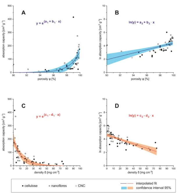
Correlation between Adsorption Capacity and Porosity/Density
The average volumetric absorption capacity was compared to material-specific di- mensions of the absorber material, such as density (δ), porosity (φ) (see Figure5A–D), but also BET surface area (SBET) and WCA. Volume-related dimensions, such as density and porosity, clearly correlate with the oil absorption capacity. The porosity and the density of a material are related via Equation (1),
φ =
1− δporous δnon−porous
·100% (1)
whereasδporouswould be the density of the final aerogel, andδnon−porousis the density of the precursor, e.g., pure lignocellulose before aerogel formation. The higher the porosity of the absorber material, the higher is also the absorption capacity. Below 95% porosity the absorption capacity comes close to zero, which can be considered as the technical limit for those materials (see Figure5A). The logarithmic absorption capacity is then almost proportional to the porosity, and becomes zero at low porosities (see Figure 5B). Vice versa, for high densities (>50 mg cm−3) the absorption capacity approaches the zero value (see Figure5C,D). These relations can be fitted by an exponential expression (parameters see Table4).
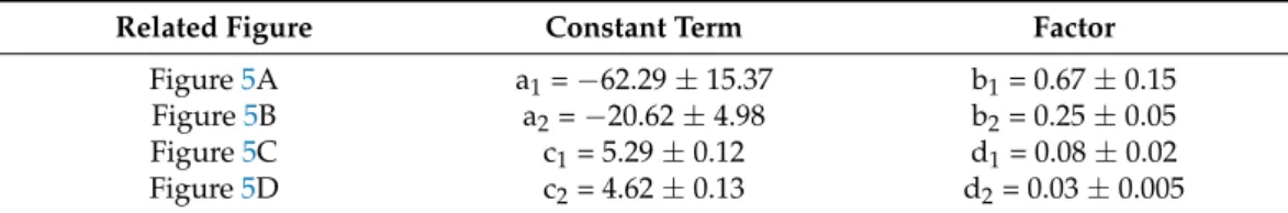
Table 4.Fit parameters to describe the relation between porosity or density and absorption capacity.
Related Figure Constant Term Factor
Figure5A a1=−62.29±15.37 b1= 0.67±0.15
Figure5B a2=−20.62±4.98 b2= 0.25±0.05
Figure5C c1= 5.29±0.12 d1= 0.08±0.02
Figure5D c2= 4.62±0.13 d2= 0.03±0.005
Regarding the cellulosic raw materials for aerogel preparation one could estimate that the dimensions of precursors (nano- or micrometer sized) would influence the porosity and, respectively, the density of the obtained aerogel. It can be seen from Figure5A–D that although low density/high porosity aerogels are produced from a nano- and micro sized fibrous precursor (CNF/MFC), this is not exclusively limited to it, since low densities and high porosities are also found in aerogels produced from bulk cellulose and BNC. Vice versa, high density and low porosity aerogels could also be manufactured from CNF/MFC, bulk cellulose and BNC. Aerogels from CNC were located exclusively in the low den- sity/high porosity region, with the lowest reported density of any aerogel in this review, 0.1 mg cm−3[162]. However, CNCs as precursors are rarely reported [114,115,162,163].
Interestingly, cellulose derivatives, such as CA, are also efficient precursors for low den- sity/high porosity aerogels [58,61,89,118]. It has to be assumed that density and porosity of cellulose based aerogels is not mainly depending on the raw materials, but likely on the