The nanofibers are eventually formed either by evaporation of solvent or freezing of the melt. The work of Miroshnichenko et al provides a representative example of the lines of research in this area by reporting cell interaction improvements when polycaprolactone nanofibers are coated with covalently bound platelet-rich plasma, broadly reviews the progress in the particular field of electrospun polyvinylidene fluoride-based materials used for bone and neural tissue engineering.
Electrospun Functional Materials toward Food Packaging Applications: A Review
Introduction
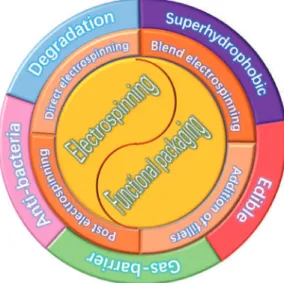
Therefore, the development of functional packaging materials based on electrospinning technology has become a hot spot in the field of food packaging. Furthermore, a conclusion is also discussed which includes the future perspective and key challenges for electrospun functional packaging materials.
Strategies for the Preparation of Functional Electrospun Materials
72] investigated the parameters such as electric field and polymer solution concentration in the electrospinning process to prepare zein nanofiber membranes. By heating the electrospun membrane, the nanofibers in the electrospun membrane can be cross-linked, and the properties such as mechanical properties can be further improved.
![Figure 2. Photographs showing the range of structures that can be produced as the concentration (wt.%) is increased at Mw = 18,000 g/mol [77]](https://thumb-ap.123doks.com/thumbv2/1libvncom/9201316.0/17.723.188.536.162.550/figure-photographs-showing-range-structures-produced-concentration-increased.webp)
Functional Materials for Food Packaging Applications
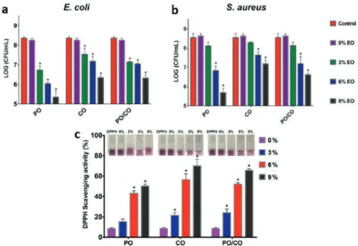
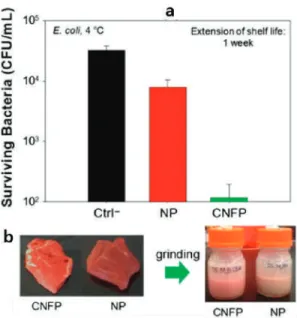
In the field of food packaging, surface modifications for electrospun fiber membrane are often used to endow the membrane with antibacterial properties. The effect of these membranes on the packaging of popular foods such as chips and bread have been investigated (Figure 14).

Conclusions and Challenges
Electrospinning of nano-/microscale poly(l-lactic acid) aligned fibers and their potential in neural tissue engineering.Biomaterials. Coaxial electrospinning of WO3 nanotubes functionalized with bioinspired Pd catalysts and their superior hydrogen sensing performance.Nanoscale. Evaluation of Aloe Vera Extract Loaded Polyvinyl Alcohol Nanofiber Webs Obtained via Needleless Electrospinning.IOP Conf.
Filled and Hollow Carbon Nanofibers by Coaxial Electrospinning of Alcell Lignin Without Binder Polymers.Adv. Characterization of the Morphology and Thermal Properties of Zein Prolamine Nanostructures Obtained by Electrospinning. Food Hydrocoll. Viscoelastic behavior of core-shell structured PLA and PVA nanofibers produced by coaxial electrospinning.Polym.
Subramanian, C.; Ugbolue, S.C.; Warner, S.B.; Patra, P. Melt Electrospinning af polycaprolacton (PCL) ultrafine fibre; MRS Online Proceedings Library Archive: Warrendale, PA, USA, 2008; Bind 1134, s.
Electrospun Nanofibers: from Food to Energy by Engineered Electrodes in Microbial Fuel Cells
Materials and Methods
The duration of the electrospinning process was close to 10 minutes to ensure at the same time a regular distribution of nanofibers, which were directly assembled on the CP without a binder and a high surface-to-volume ratio. This ordered distribution can be optimized when the thickness of the nanofibers is close to several micrometers. The electrolyte solution was based on sodium acetate (C2H3NaO2), ammonium chloride (0.31 gL−1 NH4Cl) used as a nitrogen source to aid bacterial growth, and phosphate-buffered saline (PBS) that maintained a neutral pH.
The first was an electrolyte solution based on sodium acetate (C2H3NaO2), used as a carbon energy source at a concentration of 2 gL−1 together with other compounds that can ensure the optimal operation of the SCMFCs. In the second electrolyte, PBS was added to ensure a neutral pH of the solution; due to the complexity of honey, the second electrolyte required no further addition of nutritional compounds for the micro-organisms. Anodes and cathodes of the SCMFCs were connected to a multichannel data acquisition unit (Agilent 34972A), and two different values of external resistance were applied.
Internal resistance of the SCMFCs was evaluated by Nyquist plots, using electrochemical impedance spectroscopy (EIS).
Results and Discussion
In the red box, the preferential distribution of CP/PEO-NFs on the conductive protrusions of CP is highlighted; (c) Logarithmic representation of OD measurements performed for all samples: bare inoculum (green), carbon-based material (CP, red) and CP/PEO-NFs (blue). The overall performance obtained with CP/PEO-NFS was compared to that of a reference material consisting of bare carbon-based anodes (CP). The maximum value of energy recovered Erec was reached at the highest honey concentration used (2 gL−1) for both CP/PEO-NFs and CP anodes.
At all honey concentrations, CP/PEO-NFs showed a better performance in terms of anode Erectan and CP. a) Recovered energy determined for CP/PEO-NF related to honey concentration;. Moreover, the results allowed the analysis of the resistance related to charge transfer (Rct) of both CP/PEO-NF and CP anodes. The obtained results confirmed that SCMFCs using CP/PEO-NFs as anode presented impedance values close to those achieved with a CP-based anode.
This result suggests the possibility of applying CP/PEO-NFs to achieve a large nanofiber-based interface between a CP anode and a bacterial biofilm, optimizing the adhesion of the biofilm to the anode.

Conclusions
Biochemical evaluation of bioelectricity production process from anaerobic wastewater treatment in a single chamber microbial fuel cell (MFC) using glass wool membrane. Biosens. Utilization of olive mill wastewater to improve performance in electricity generation from domestic wastewater using single-chamber microbial fuel cells. Bioresour. Maximizing energy recovery from homeostasis in the microbial fuel cell via synergistic short-chain volatile fatty acid conversion. Bioresour.
Evaluation of energy conversion efficiencies in microbial fuel cells (MFCs) using fermentable and non-fermentable substrates.Water Res. Wastewater discharge reduction and bioenergy recovery in an osmotic microbial fuel cell for domestic wastewater treatment.Desalination. New electrode materials to improve bacterial adhesion and increase power generation in microbial fuel cells (MFCs). Water Sci.
Electrochemical and impedance characterization of microbial fuel cells based on 2D and 3D anodic electrodes operating continuously with seawater microorganisms. Bioresource.
Electrospun Cadmium Selenide
Nanoparticles-Loaded Cellulose Acetate Fibers for Solar Thermal Application
Materials and Methods 1. Materials
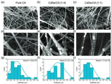
The incident wavelength was varied from 300 to 1100 nm and the absorbance of the fibers was recorded. CA fibers were filled with different concentrations of CdSe (CdSe:CA ratio 1:4 and 1:1, m/m) to analyze the successful incorporation of CdSe into CA fibers and observe the resulting photosensitive properties of the fibers as provided by CdSe NPs. The entire electrospinning of CdSe-CA composites was analyzed by visual inspection during spinning and obtained fiber images (Figure 1).
This may be due to the difficulty in achieving a homogeneous distribution and a stable suspension of CdSe in the rotating rod. The structure of the CdSe-filled CA fibers was characterized by X-ray diffraction (XRD) as shown in Figure 3. XRD peaks of CdSe at 2θ and 50° were observed in the CdSe-filled fibers, while these peaks were absent in the pure CA fiber sample.
As shown in Figure 4a, the absorbance of CA fibers increased with increasing CdSe content, with the light absorption edge around 700 nm for CdSe-loaded CA fibers.
Physico-Chemically Distinct Nanomaterials
Synthesized from Derivates of a Poly(Anhydride) Diversify the Spectrum of Loadable Antibiotics
Results
However, amikacin, neomycin and ciprofloxacin were found to be insoluble in ethanol, and thus insoluble in PMVE/MA-Es solutions. Therefore, nanofibers were obtained from PMVE/MA-Ac solutions in combination with all antibiotics, but PMVE/MA-Es solution was used only with cefotaxime. PMVE/MA-Ac nanofibers with no encapsulated compound were the narrowest in diameter (126±28 nm), which sharply contrasts with uncharged PMVE/MA-Es fibers (871±159 nm).
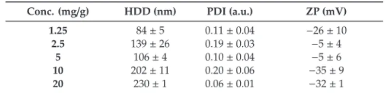
Encapsulation of the compounds increased the diameter of PMVE/MA-E and PMVE/MA-Ac nanofibers by a minimum of 1.6 times (PMVE/MA-Es/cefotaxime) and a maximum of 5.0 times (PMVE/MA-Ac/amikacin). Given these results, nanoparticles made of 10 mg/g PMVE/MA-Es were selected for further studies. Representative TEM image and diameter frequency histogram of PMVE/MA-Es nanoparticles synthesized by solvent displacement method.
Physicochemical properties and encapsulation efficiency (EE) of PMVE/MA-Es nanoparticles loaded with antibiotics.
Discussion
In contrast, the size of PMVE/MA-Es nanoparticles changed significantly (increased by approximately 25%) for some antibiotics, although not as dramatically as in charged PMVE/MA-Ac nanofibers. These magnitude changes do not appear to be related to their MWs, nor to their EEs. Despite the two aminoglycosides tested, amikacin and neomycin, with similar MWs (585.6 and 614.6 g/mol, respectively) and chemical structures (see Figure 1), the size changes of their encapsulating nanostructures (625 vs. 304 nm in nanofibers and 253 vs. 209 nm in nanoparticles) and their EEs (14% vs. 40%) are very different. .
Nevertheless, when encapsulated in both nanomaterials, all tested antibiotics exhibited similar antibacterial activity to their free forms, indicating that none of the synthesis methods used significantly modified their chemical structures.
Conclusions
5-aminolevulinic acid-incorporated poly(vinyl alcohol) nanofiber-coated metal stent for application in photodynamic therapy.Int. Development of a novel delivery system based on drug-loadable electrospun nanofibers for psoriasis treatment. Pharmaceuticals. Evaluation of the cytotoxicity, genotoxicity and mucus permeation capacity of various surface-modified poly (anhydride) nanoparticles designed for oral drug delivery. Int.
Favorable microwave-assisted suzuki polycondensation for the synthesis of alternating aniline-fluorene copolymers as molecular templates with solvent-sensing properties. Polymers. Drug delivery system based on cyclodextrin-naproxen inclusion complex incorporated into electrospun polycaprolactone nanofibers. Colloids Surf. Polyhydroxy surfactants for the formulation of lipid nanoparticles (sln and nlc): Effects on particle size, physical stability and matrix structure. Int.
Molybdenum cluster-loaded plga nanoparticles: An innovative theranostic approach for the treatment of ovarian cancer.Eur.
Micro- and Nanostructures of Agave Fructans to Stabilize Compounds of High Biological Value
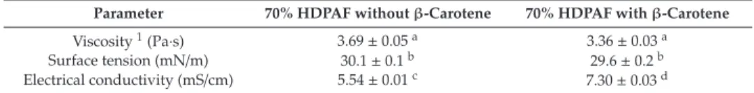
The morphology and size of the obtained fibers were both determined by the scanning electron microscopy (SEM) technique with a Hitachi-S-4800 (Hitachi High-Technologies Corporation, Tokyo, Japan). The difference may be related to the type of surfactant used, but mainly to the biopolymer concentration (70%). A polymer concentration of 70% (w/w) was used, which allowed the formation of a network of polymer chains and sufficient entanglement to electrostretch the solution, obtaining continuous fibers (Figure 1).
This indicates that almost all of the loaded compound was encapsulated in the center of the fibers. The thermal stability of the fibers in the absence of β-carotene (Figure 2b) was characterized by presenting a first weight loss of 5.0% at 100◦C, which is associated with moisture content. This can be explained due to the nature of the compounds and their affinity between β-carotene and HDPAF.
The photostability of the fibers was evaluated by exposing the fibers to ultraviolet A (UVA).
Preparation, Characterization and Properties of Porous PLA/PEG/Curcumin Composite Nanofibers
Experimental 1. Materials
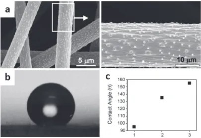
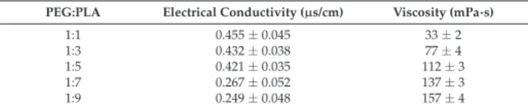
The wettability of the PLA/PEG/Cur CNFMs was characterized using an optical contact angle (CA) measuring instrument (Krüss DSA100, Krüss Company, Hamburg, Germany). The surface morphologies of the electrospun PLA/PEG/Cur CNFs with different weight ratios (PEG:PLA) were examined by SEM. Table 2 illustrates that with the decrease in the weight ratio (PEG:PLA), the mean diameters of the CNFs decreased.
Moreover, the pore distributions of the CNFMs with the weight ratios of 1:7 and 1:9 (PEG:PLA) showed more uniformity. The CA values of the PLA/PEG/Cur CNFMs with different weight ratios (PEG:PLA) were obtained with an optical (CA) measuring instrument (Table 4). The electrical conductivity and viscosity of the spinning solutions with different weight ratios (PEG:PLA) were investigated.
CA measurements illustrated that the CA of the CNFMs increased as the weight ratio decreased.
![Figure 3. A schematic of the experimental setup used in the multi-jet electrospinning process [85].](https://thumb-ap.123doks.com/thumbv2/1libvncom/9201316.0/19.723.157.580.197.566/figure-schematic-experimental-setup-used-multi-electrospinning-process.webp)
![Figure 5. Schematic representation of the coaxial needle electrospinning set-up [94]. © The Korean Society of Pharmaceutical Sciences and Technology 2012.](https://thumb-ap.123doks.com/thumbv2/1libvncom/9201316.0/20.723.199.530.611.904/figure-schematic-representation-electrospinning-society-pharmaceutical-sciences-technology.webp)
![Figure 6. Structure diagram of coaxial fiber [97]. © Elsevier Inc. All rights reserved 2016.](https://thumb-ap.123doks.com/thumbv2/1libvncom/9201316.0/21.723.117.605.334.572/figure-structure-diagram-coaxial-fiber-elsevier-rights-reserved.webp)
![Figure 8. Electrospun hybrid mats; its antimicrobial concept and projected future applications as packaging material for meat and meat-based products [117]](https://thumb-ap.123doks.com/thumbv2/1libvncom/9201316.0/24.723.131.597.348.732/figure-electrospun-antimicrobial-projected-applications-packaging-material-products.webp)
![Figure 11. Appearance changes of strawberries stored at 21 ◦ C. (a) Control; (b) packed with fresh-keeping film and (c) packed with PVA/cinnamon essential oil /b-CD nanofilm [141]](https://thumb-ap.123doks.com/thumbv2/1libvncom/9201316.0/29.723.190.533.380.724/figure-appearance-changes-strawberries-control-cinnamon-essential-nanofilm.webp)