Full Terms & Conditions of access and use can be found at
http://www.tandfonline.com/action/journalInformation?journalCode=lpte20
Download by: [Monash University Library] Date: 01 March 2016, At: 18:47
Polymer-Plastics Technology and Engineering
ISSN: 0360-2559 (Print) 1525-6111 (Online) Journal homepage: http://www.tandfonline.com/loi/lpte20
Enhancement of Interlaminar Fracture Toughness of Carbon Fiber/Epoxy Composites Using Silk
Fibroin Electrospun Nanofibres
Cuong Manh Vu & Houyng Jin Choi
To cite this article: Cuong Manh Vu & Houyng Jin Choi (2016): Enhancement of Interlaminar Fracture Toughness of Carbon Fiber/Epoxy Composites Using Silk Fibroin Electrospun Nanofibres, Polymer-Plastics Technology and Engineering, DOI:
10.1080/03602559.2015.1132459
To link to this article: http://dx.doi.org/10.1080/03602559.2015.1132459
Accepted author version posted online: 01 Mar 2016.
Submit your article to this journal
View related articles
View Crossmark data
1
Enhancement of Interlaminar Fracture Toughness of Carbon fiber/Epoxy Composites using silk fibroin electrospun nanofibres
Cuong Manh Vu1,, Houyng Jin Choi2
1Chemical department, Le Qui Don Technical University, Ha Noi, Viet Nam
2Department of Polymer Science & Engineering, Inha University, Incheon, Korea Corresponding author. Cuong Manh Vu Email: [email protected]
Abstract
In this paper, the effect of silk fibroin nanofibres (nSF) as a toughening agent of Carbon fiber/ fabric reinforced Epoxy Composites (CF/EP) is experimentally investigated. The composites showed up to 30% improvement in Mode II fracture toughness the at 0.1 wt.% of nSF content. The scanning electron microscopy (SEM) observation revealed that the fracture surface of nSF modified CF/EP appearance of the broken fiber and the ductile–like matrix cracks showed a good adhesion between matrix resin and carbon fibers which are reasons for enhance mode II interlaminar fracture toughness.
Downloaded by [Monash University Library] at 18:47 01 March 2016
2
KEYWORDS: Fracture toughness, silk fibroin nanofibres, CF/EP, electrospinning, Mode II fracture toughness
INTRODUCTION
Carbon fiber is one of most important fiber which has been used as reinforced material in preparing light–weight composites for structural applications such as aerospace, marine and automotive because of its superior mechanical properties and low densities. For preparing fiber reinforced polymer composites (FRP) aims, this fiber is embedded in a relatively compatible polymer matrix [1]. The most widely used polymeric matrixs are thermoset epoxies that provide superior thermal, mechanical and electrical properties, dimensional stability and chemical resistance. However due to intrinsic brittleness of epoxy matrix after cured that strength properties of CF/EP composites are sensitive to failure modes such as transverse cracking, longitudinal cracking and delamination between adjacent layers. Since fiber are mechanically stronger than the matrix [2], the matrix fracture toughness is the key material property that controls damage initiation and growth in composites, especially in through–the–thickness properties, such as
delamination properties. Delamination is one of the major failure mechanisms associated with composites that allow cracks to grow between the plies of a laminate. The
investigation before showed that, most epoxy resins are brittle and have Mode I fracture toughness of about 80–300 J/m2 in the delamination mode [3–5]. Considering delamination growth from the point of view of fracture mechanics, interlaminar fracture toughness still plays an important role in damage propagation of CF/EP [6]. In laminate composites based on epoxy matrix, delamination is strongly related to the brittle nature of epoxy matrix. In
Downloaded by [Monash University Library] at 18:47 01 March 2016
3
this case enhancing the matrix toughness may leads to the improvement of the
interlaminar fracture toughness of laminate composites. Previous work has focused on enhancing interlaminar fracture toughness of composites by incorporating a small amount of nano–materials (carbon nanotube [7, 8], vapor grow carbon fiber [9, 10], nano–cellulose
[11], ...) to the epoxy matrix. In addition, using nanomaterials for the CF/EP composites could also satisfy the recent demands on the superior performances and more durability as well as for higher reliability in the fields of advanced applications [12–17].
In this work for modification epoxy matrix the work focused on using nSF as
nanomaterial reinforcer that fabrication by using electrospinning. Electrospinning was patented by Anton Formhals in 1934 and is a combination of two techniques which are electrospray and spinning of fibres [18] which has been very interesting for the recent years for fabrication nanofibers with the help of electrical forces. Silk is an ancient and the only natural filament fibre which is used for thousands of years and for the year 2011, China (126 ktons), India (20.4 ktons), Viet Nam (7.05 ktons), Romania (2.1 ktons), Thailand (1.6 ktons) and Uzbekistan (1.2 ktons) are the six major silk producers in the world [19]. Silk, is a fine, strong continuous fibroin filament produced by the larva of certain insects especially the cultured silkworms constructing their cocoons. Raw silk fibre has natural impurities such as wax, carbohydrates, inorganic matter and pigment less than 3% wt of a fibre. In a composition of a silk fibre, fibroin content is about 70–
80% and the content of sericin, which is silk gum and usually removed in processing, is about 20–30% [20]. Silk fibroin polymers contain protein series and are responsible for cocoon and web formation, nest building, etc. [21, 22]. As they have mostly β–sheet
Downloaded by [Monash University Library] at 18:47 01 March 2016
4
structures consisting of short side chain amino acids in the primary sequence, they permit tight packing of piled sheets of hydrogen bonded anti–parallel protein chains. Because of both large hydrophobic and smaller hydrophilic areas they allow to promote the assembly of silk which is very good in strength and resiliency [23]. The studies on the silk fibroin from silkworm cocoons were first reported in 1994 [24]. A hexafluorisopropanol solvent is used and nano scaled fibres can be produced by the electrospinning process. This process is similar to the spinning process of a silkworm where the polymer solution is subjected to a high electric field and this field overcomes the surface tension so polymer ejects, stretches and deposits a kind of nonwoven mat. Therefore, with this technique the
polymer fibres of micrometres produce fibres in nanometre scales. Nowaday, Silk fibroin is preffered using for for biomedical application [25–27]. However the using of nSF as toughness agent for thermoset resin such as EP and CF/EP composites have no published until now.
The nSF were first prepared by wet electrospinning using methanol bath and then added to EP using as a matrix for fabrication CF/EP composites by using methyl
hexahydrophthalic anhydride (MHHPA) as a curing agent. The bonding between cacbon fibers and EP were accessed by IFSS and interlaminar fracture toughness of CF/EP composites were accessed by using Mode II fracture toughness. The effect of different contents of nSF on the morphology and thermo–mechanical properties of the prepared nanocomposites also was examined.
1. EXPERIMENTAL
Downloaded by [Monash University Library] at 18:47 01 March 2016
5 1.1. Materials
Silk cocoons were obtained from Vietsilk Limited Company Lam Dong Province, Vietnam was used as nanofiber resource. Besides, lithium bromide (LiBr, Sigma
Aldrich), sodium carbonate, methanol, formic acid (Merck, Germany), cellulose dialysis tube (12 KDa, Sigma Aldrich). Plain woven carbon cloth (Toray, Japan). The epoxy resin used is diglycidyl ether of bisphenol A (Epon 828) which was purchased from Shell Chemical and has an epoxide equivalent weight (EEW) of 185–192 g/eq. MHHPA purchased from Lindau Chemical (England), was chosen as the curing agent. 1– metyl imidazol (NMI) purchased from BASF (Germany) was used as the accelerator. The chemical structures of DGEBA, MHHPA, NMI and are shown in Figure 1.
1.2. Fabrication Of Nsf
Silk cocoons were boiled in 0.02 M aqueous Na2CO3 solution for 1 h to remove sericin, washed with deionized water and dried at 37°C overnight. The degummed silk was dissolved in 9.3 M LiBr at 60 °C for 4 hours, dialyzed in a cellulose tube against distilled water for 72 hours and then lyophilized. The prepared SF sponge was then dissolved in formic acid under stirring for 3 hours at room temperature to yield 13 wt% SF solution.
Subsequently, the obtained solution was filled in 1 ml syringe with 22 G blunted stainless steel needle. Electrospinning (Electrospinz, New Zealand) was carried out at 20 kV with a constant flow rate of 0.25 ml.h–1. The electrospun fibers were collected in the methanol coagulation bath for direct recovery of β–sheets. The methanol bath was placed 13 cm under the needle tip. To determine morphology, the fiber mat was attached on an aluminum stub, sputter coated with gold, and imaged with a Scanning Electron
Downloaded by [Monash University Library] at 18:47 01 March 2016
6
Microscope (SEM, Joel JSM 6360, Japan). The morphology of nSF from Figure 2 showed that the nSF was generated with randomly–aligned fiber web having a diameter ranging from 50 to 100 nm with concentration 13 wt.%.
1.3. Preparation Of CF/EP Composites
nSF was directly mixed into the epoxy resin with different contents (0, 0.03, 0.05, 0.1 wt.%) at 900C for 60 min using a process homogenizer at a rotating speed of 15.000 rpm.
The mixture was then sonicated for 15 min by using an ultrasonic homogenizer. The curing agent and accelerator were added in the mixture with a molar ratio of
EP/MHHPA/NMI=1/0.87/0.028, after which the mixture was degassed in a vacuum oven for 15 min. The obtained mixture was hand lay–upped with plain–woven carbon fabric which its fraction of volume was 50 ± 2% (the volume fraction of EP/CF was 1:1). About 10 layer of CF was used (the thickness of one CF layer equal to 0.4 mm). Curing was performed at 1300C for 1 h and 1500C for 1 h in a convection oven.
1.4. Resin Fracture Toughness Test
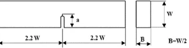
All neat resin and nSF–modified epoxy resin were cured at 1300C for 1 hour and 1500C for 3 hours. The single edge notch bend (SENB) specimen were used to determine the fracture toughness (KIC), as shown in Figure 3 according to ASTM D5045–99 was
calculated from equation from 1 and 2. The notch tip was machined using a diamond saw.
The pre–crack was generated using tapping a fresh razor blade. After fabricating SENB specimens, the crack tip was observed by using the optical microcopy as shown in Figure 4.
Downloaded by [Monash University Library] at 18:47 01 March 2016
7 )
2 (
/
1 f x
BW
KIC PC , W=2B (1)
2 / 3
2 2
/ 1
) 1 )(
2 1 (
)]
7 . 2 93 . 3 15 . 2 )(
1 ( 99 . 1 6 [ )
( x x
x x x
x x x
f , x=a/W (2)
1.5. Interfacial Shear Strength
To evaluate the effect of nSF on the interfacial shear strength (IFSS) of single carbon fiber and epoxy, micro–droplet test was conducted by using Model HM410 instrument carbon single fiber detached from woven fabric, and then was attached to a thin concave plastic or hardboard with double sided adhesive tape or adhesive as were showed in Fig.
5. Epoxy micro–droplet with various ratio (0 wt.%, 0.03 wt.%, 0.05 wt.% and 0.1 wt.%) was adhered on a carbon single fiber with an embedded length of 40–80 µm by using a fine size applicator. The embedded length was measured using an optical microscopy observation. The IFSS between single fiber with an embedded length of 40–80 µm by using a fine size applicator. The embedded length was measured using an optical
microscopy observation. The IFSS between single carbon fiber and epoxy was calculated by the following equation:
f
F D L
Where is the interfacial shear strength, F is the critical load, Df is the single carbon fiber diameter, and L is the embedded length into resin, respectively. At least 20
experiments were tested for each testing specimen.
Downloaded by [Monash University Library] at 18:47 01 March 2016
8 1.6. Tensile Test
The tensile properties of the samples were measured using a Instron 5582–100KN testing machine according to ASTM D3039–08. The specimen gage length was 100 mm and the testing speed was set to 1mm/min. The specimen dimension was 200 mm x 25 mm x 2 mm. Glass fiber reinforced plastic/epoxy tabs or aluminum tabs with thickness of 1.5 mm or 2mm were attached at both ends of the specimen by an adhesive.
1.7. Mode–II Interlaminar Fracture Toughness Test
The mode–II interlaminar fracture toughness test (GIIC) was evaluated by using the end–notch flexural (ENF) test at a loading rate of 1 mm/min as illustrated in Figure. 5 according to JIS K7086 standard. The nominal specimen width (W) was 20 mm, initial crack length (a0) 25 mm and total specimen length 120 mm. For testing, the specimen was placed in a three–point bending fixture with the haft span length (L) set at a 50 mm and the ratio (a0/L) maintained at 0.5. Expressions for the calculation of the mode II critical strain energy release rate (GIIC) are derived from the Iwin and Kies expression for fracture energy:
2 IIC 2
P dC
G W da (1)
GIIC was calculated by using the direct beam theory method which used the ENF compliance expression given by Russell and Street.
3 3
3
2 3
8
L a
C EWh ;
2 3
9 8 dC a
da EWh ;
3 3
3
2 3
8 L a
E CWh (2)
Downloaded by [Monash University Library] at 18:47 01 March 2016
9
2 2 2 3
9
IIC 16 G a P
EW h (3).
An expression for E can be obtained from (2) which substitutes into Equation (4) (for beam under small defection), yielding:
2
3 3
9
2 (2 3 )
IIC
G a P
W L a (4)
3
1 1 3
0 1 3 3 2 0 0
1 L
C C C a
C
a (5)
Where Pc is the critical load, C is the compliance (displacement/load; δ/P), W is the width, a is the crack length, E is the flexural modulus of the beam with the absence of pre–crack, h is half the specimen thickness, C1 is the compliance corresponding to the critical load. C0 is the compliance corresponding to the initial crack, GIIC the critical strain energy release rate.
1.8. Dynamic Mechanical Analysis Test
DMA8000 instrument with a chuck distance of 20 mm was used to perform the DMA studies in order to evaluate tan δ and Tg. DMA gives both the storage modulus and the loss modulus characteristics as a function of temperature. The measurements were carried out at a heating rate of 20C/min from 250C to 2500C at fixed frequency of 1 Hz with the three point bending mode. The samples of DMA testing had the approximate dimensions of 40 mm in length, 10 mm in width and 2 mm in thickness.
Downloaded by [Monash University Library] at 18:47 01 March 2016
10 1.9. Scanning Electron Microscopy Observations
The fractured surface of testing specimens were observed by using scanning electron microscopy (SEM–JEOL JSM 6360, Japan). Prior to SEM observation, all samples were coated a thin layer of gold to avoid electrical charging.
2. RESULTS AND DISCUSSIONS 2.1. Resin Fracture Toughness
The fracture toughness of nSF–epoxy with various contents (0 wt.%, 0.03 wt.%, 0.05 wt.%, and 0.1 wt.%) was determined by the three point bending method with SENB specimens. The testing specimens were conducted at the cross–head speed of 10 mm/min, which was fast enough to prevent the viscoelastic behavior of the epoxy. The
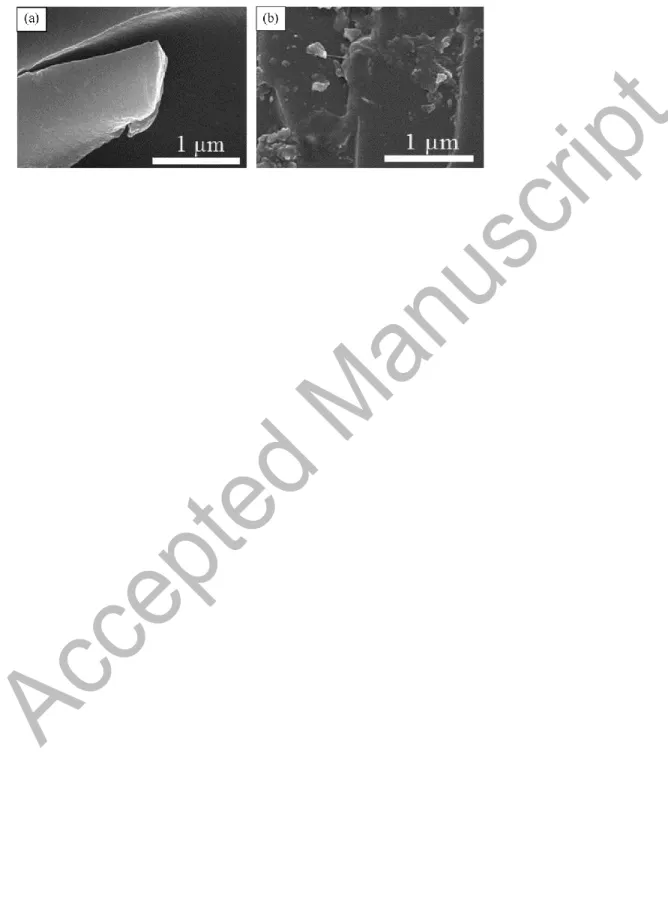
experimental results in Figure 7 showed that The KIC values of epoxy resin were slightly improved with adding nSF. With the addition of 0.1 wt.% of nSF, the fracture toughness was improved by 28.3% from 0.639 MPa.m1/2 to 0.82 MPa.m1/2. In SEM observation, the smooth fracture surface of the neat epoxy pronounced a typical fracture behavior as shown in Fig 8a. It was noticeable that a smooth mirror–like surface, micro–flow lines and river pattern was observed. With the addition of nSF, the roughness fracture surface was revealed suggesting the crack propagation could be delayed so that more energy was required. This could be attributed the crack encountered nano–fibers bridging as shown in Fig 8b.
2.2. Micro–Droplet Test A
Downloaded by [Monash University Library] at 18:47 01 March 2016
11
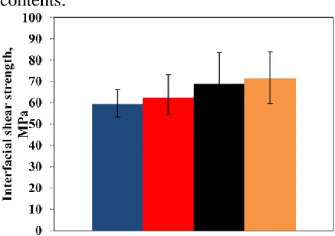
The interfacial shear strength (IFSS) between fiber and matrix have been strongly affected by the presence of nanofibers, such as carbon nanotube, nanoclay, nanosilica, etc. [28–30]. In this study, the micro–droplet test was used to evaluate the IFSS of single carbon fiber and epoxy droplets with the addition of nSF. Fig. 9 showed that the IFSS gradually enhanced with an increase of nSF content. The IFSS value of the modified composite at0, 0.03, 0.05, 0.1 wt.% of nSF were 59.45, 62.39, 68.54 and 71.44 MPa. It mean that, at 0.1 wt.% of nSF content, the IFSS strongly increased by 20%. The IFSS value of the modified composite at 0.1 wt.% nSF was increased from 59.45 MPa to 71.44 MPa.. It found that the role of nSF contributed to relatively improve of interphase
between single carbon fiber and epoxy.
2.3. Tensile Test
The effect of nSF contents on the mechanical behavior of the CF/EP composites was investigated. For the modified composite, the tensile strength and Young`s modulus slightly increased with the addition of nSF contents as summarized in Fig. 10. It was worth noting that at 0.05 wt.% nSF, the tensile strength for the modified composite increased by 4.8% higher than that of the unmodified composite. It is pronounced that the addition of nano–materials plays an important role in improving the strength of the
interface. This could be attributing to the dependence of the tensile strength of the nanoreinforced interface to the nanosized fillers which characterized by large surface areas per unit gram. Thus, addition of small amount of nSF leading to the number of adhesively jointed points with carbon fibers was very low which had no effect on the tensile strength of the CF/EP composites.
Downloaded by [Monash University Library] at 18:47 01 March 2016
12
2.4. Mode–II Interlaminar Fracture Toughness Test
In the end notch flexure (ENF) test, the specimen is loaded in a three point flexural fixture as shown in Fig. 6. The experimental results of Fig.11 showed a plot of the interlaminar fracture toughness of the CF/EP composites as a function of nSF of content.
With the gradual addition of nSF content, the critical energy release (GIIC) also gradually increased. At 0.1 wt.% nSF, the GIIC increased by 30%. It was worth nothing that the fracture toughness of the CF/EP composites increased from the energy–dissipating events, such as fiber matrix debonding, fiber pull–out and bridging as well as the fracturing of the matrix and fibers [31–33]. The fractured surfaces of ENF specimens were examined using SEM. Fig. 12 (a) showed that the sheared hackle markings in the epoxy matrix, which was characteristic of brittle fracture. Moreover, there was almost no broken fiber bridging, and the cracks propagated along the fiber–matrix. It showed that the adhesion between resin and carbon fiber was relatively weak. On the other hand, Fig. 12 (b) with the appearance of the broken fiber and the ductile–like matrix cracks showed a good adhesion between matrix resin and carbon fibers. This could be attributed to the tougher matrix when incorporated nSF. The higher toughness was achieved due to micro/nano– cracks pined via forming nanofiber bridging. It considered that such reasons improved the critical energy release rate.
2.5. Dynamic Mechanical Analysis Test
Effect of nSF on the thermal mechanical behavior of the CF/EP composites was
determined using dynamic mechanical analysis (DMA). The results in Fig. 13 (a) showed that the glass transition temperature (Tg) of the composite with various contents of nSF (0
Downloaded by [Monash University Library] at 18:47 01 March 2016
13
wt.%, 0.03 wt.%, 0.05 wt.% and 0.1 wt.%) were 165.30C, 162.030C, 161.010C and 160.830C, respectively. It found that there was a tendency for the slight decrease of Tg in the composite with the presence of nSF. On the other hand, the addition of nSF affected the damping of the CF/EP composites through the determination of the loss tangent value (tan δ), namely the tan δ values of the modified composite was lower than that of the unmodified composite. The tan δ value of 0.1 wt.% nSF decreased by 15% from 0.5744 to 0.4882. This can be related to the non–dissipative nature of the filler, which reduces the viscolelastic response of the composite. The results in Fig. 13 (b) performed that the storage modulus of the CF/EP composites slightly increased with an increase of nSF content. The addition of 0.1 wt% of nSF yielded a 5.75% increase of the storage modulus at 250C. These results confirmed that the incorporation of nSF improvement of the stiffness of the composite.
3. CONCLUSIONS
In this study, we investigated how to fabricate randomly–aligned web of SF nanofibers form the electrospinning process. The effects of nSF on the mechanical properties of the CF/EP composites were determined.
– The fracture toughness of nSF–epoxy was improved by 28.3% with the addition of 0.1 wt.% nSF.
– The incorporation of 0.1wt.% nSF contributed to improvement of the IFSS between single carbon fiber and micro–droplet epoxy with an increase by 20%.
Downloaded by [Monash University Library] at 18:47 01 March 2016
14
– There was a slight increase of the tensile strength by about 5% with the addition of 0.05 wt.% nSF.
– There was an increase of the mode–II interlaminar fracture toughness (GIIC) at 0.1wt.% nSF by 30%.
REFERENCES
1. Jin Z, Khunlavit C, Shuai H, Chun H., Wang. Hybrid composite laminates reinforced with glass/carbon woven fabrics for lightweight load bearing structures.
Materials and Design 2011; 36: 75 – 80.
2. Hull D. An introduction to composite materials. Cambridge University Press; 1981.
3. Garg A, Ishai O. Hygrothermal influence on delamination behavior of graphite/epoxy laminates. Eng Fract Mech 1985; 22(3):413–27.
4. Keary PE et al. Mode I interlaminar fracture toughness of composites using slender double cantilevered beam specimens. J Compos Mater 1985;19:154–77.
5. Whitney JM, Browning CE, Hoogsteden W. A Double cantilever beam test for characterizing Mode I delamination of composite materials. J Reinf Plast Compos 1982;1(4):297–313.
6. Masahiro A, Tatsuya S, Satoshi H, Hiroaki I, Ning H, Marino Q. Mixed modes interlaminar fracture toughness of CFRP laminates toughness with CNF interlayer, Acta Mechanica Solida Sinica. 2012; 25(3):322.
7. Yokozeki T, Iwahori Y, Ishibashi M, Yanagisawa T, Imai K, Arai M, et al. Fracture toughness improvement of CFRP laminates by dispersion of cup–stacked carbon nanotubes.
Compos Sci Technol 2009;69(14):2268–73.
Downloaded by [Monash University Library] at 18:47 01 March 2016
15
8. Lee S–H, Kim H, Hang S, Cheong S–K. Interlaminar fracture toughness of composite laminates with CNT–enhanced nonwoven carbon tissue interleave. Compos Sci Technol 2012;73:1–8.
9. Li Y, Hori N, Arai M, Hu N, Liu Y, Fukunaga H. Improvement of interlaminar mechanical properties of CFRP laminates using VGCF. Compos A Appl Sci Manuf 2009;40(12):2004–12.
10. Arai M, Noro Y, Sugimoto K–i, Endo M. Mode I and mode II interlaminar fracture toughness of CFRP laminates toughened by carbon nanofiber interlayer. Compos Sci Technol 2008;68(2):516–25.
11. Mohamed H. Gabr, Nguyen T. Phong, Kazuya Okubo, Kiyoshi Uzawa,Isao Kimpara, Toru Fujii Thermal and mechanical properties of electrospun nano–celullose reinforced epoxy nanocomposites Polymer Testing 2014; 37:51– 58.
12. Doris W.Y.W, Lin L, P. Terry McCrail, Ton P, Paul J. H. Improved fracture toughness of carbon fibre/epoxy composite laminates using dissolvable thermoplastic fibres. Composites: Part A. 2010; 41:759–67.
13. Ke W, Ling C, Jingshen W, Mei L.T, Chaobin H, and Albert F.Y. Epoxy Nanocomposites with Highly Exfoliated Clay: Mechanical Properties and Fracture Mechanisms. Macromolecules. 2005; 38:788–800.
14. S Alessi, D Conduruta, G Pitarresi, C Dispenza, G Spadaro. Accelerated ageing due to moisture absorption of thermally cured epoxy resin/polyethersulphone blends.
Thermal, mechanical and morphological behaviour. Polymer Degradation and Stability.
2011; 96:642–648.
Downloaded by [Monash University Library] at 18:47 01 March 2016
16
15. Hiroaki M, Michael J.R, Lawrence T.D. Thermo–physical properties of epoxy nanocomposites reinforced by carbon nanotubes and vapor grown carbon fibers.
Thermochimica Acta. 2006; 442:67–73.
16. Ashish W, Ajay G, Olivier R, Luca M, Frederic L, Larissa G, Stephan V.L, Aart W.V.V, Ignaas V. The effect of adding carbon nanotubes to glass/epoxy composites in the fibre sizing and/or the matrix. Composites Part A: Applied Science and
Manufacturing 2010; 41(4):532–8.
17. Naveed A. S, Ricky S.C. W, Jang K. K, Christopher C.K.L, Arshad M. Mode I interlaminar fracture behavior and mechanical properties of CFRPs with nanoclay–filled epoxy matrix. Composite: Part A 2007; 38, :449–60.
18. J.D. Schiffman, C.L. Schauer. A Review: Electrospinning of Biopolymer Nanofibers and their Applications Polym. Rev 2008; 48 (2):317–352.
19. S. Muge Y, Nihal S, Suat C. Biomaterial applications of silk fibroin electrospun nanofibres. Microelectronic Engineering 2015; 146: 43–47.
20. M.L. Gulrajani, Rev. Prog. Color. Relat. Top. 22 (1) (1992) 79–89.
21. D.L. Kaplan, S.M. Mello, S. Arcidiacono, S. Fossey, K.W.M. Senecal, Protein Based Materials, Birkhauser, Boston, 1998; 323:103–131.
22. P. Wong, C. Foo, D.L. Kaplan. Genetic engineering of fibrous proteins: spider dragline silk and collagen. Adv. Drug Deliv. Rev 2002; 54 (8):1131–1143.
23. J. Perez–Rigueiro, C. Viney, J. Llorca, M. Elices. Mechanical properties of single– brin silkworm silk. J. Appl. Polym. Sci 2000; 75:1270–1277.
24. J. Cappello, K.P. MacGrath, C. Viney, in: D. Kaplan, W. Adam, B. Farmer (Eds.), Spinning of Protein Polymers Fibers, ACS, Washington, DC, 1994, pp. 311–327
Downloaded by [Monash University Library] at 18:47 01 March 2016
17
25. F. Han, S. Liu, X. Liu, Y. Pei, S. Bai, H. Zhao, Q. Lu, F. Ma, D.L. Kaplan, H. Zhu.
Woven silk fabric–reinforced silk nanofibrous scaffolds for regenerating load–bearing soft tissues. Acta Biomater 2014; 10:921–930.
26. Q. Lu, X.L. Wang, S.Z. Lu, M.Z. Li, D.L. Kaplan, H.S. Zhu. Nanofibrous architecture of silk fibroin scaffolds prepared with a mild self–assembly process.
Biomaterials 2011; 32:1059–1067.
27. B. Kundi, N.E. Kurland, S. Bano, C. Patra, F.B. Engel, V.K. Yadavalli, S.C. Kundu.
Silk proteins for biomedical applications: Bioengineering perspectives. Prog. Polym. Sci, 2014;39: 251–267.
28. Li Y, Thomas W. H, Anthony G.E, Gary L. B, David. G. S, and Gary E. W.
Electrospinning and Stabilization of Fully Hydrolyzed Poly(Vinyl Alcohol) Fibers.
Chemistry of Materials 2003; 15: 1860–4.
29. Bin D, Hak Y.K, Se C.L, Douk–R.L, and Kyung J.C. Preparation and
characterization of nanoscaled poly(vinyl alcohol) fibers via electrospinning. Fibers and Polymers 2002; 3:73–9.
30. Surawut C, Pitt S. Fabrication of Aligned Poly(vinyl alcohol) Nanofibers by Electrospinning Journal of Nanoscience and Nanotechnology 2006; 6:125–9.
31. Masanobu H, Ken–ichi T, Toru F. Strength and damage accumulation of carbon fabric composites with a cross–linked NBR modified epoxy under static and cyclic loadings. Composite Structure 1995;32:357–66.
32. Yasuhiro N, Kazuya O, Toru F, Kazumasa K. Fatigue crack constraint in plain–woven CFRP using newly–developed spread tows. International Journal of Fatigue 2006; 28:1248–53.
Downloaded by [Monash University Library] at 18:47 01 March 2016
18
33. Shafi U.K, Arshad M, Rizwan H, Jang–Kyo K. Fatigue damage behaviours of carbon fiber–reinforced epoxy composite. Composite Science and Technology 2010; 70: 2077–85.
Downloaded by [Monash University Library] at 18:47 01 March 2016
19 Figure 1: Chemical structures of the materials used
Downloaded by [Monash University Library] at 18:47 01 March 2016
20 Figure 2: The morphology of nSF
Downloaded by [Monash University Library] at 18:47 01 March 2016
21
Figure 3. Dimension of the single edge notched bending specimen
Downloaded by [Monash University Library] at 18:47 01 March 2016
22
Figure. 4. (a) The initial notch, (b) A pre-crack using a fresh razor blade
Downloaded by [Monash University Library] at 18:47 01 March 2016
23
Figure. 5. Experimental arrangement for the micro-droplet test: (a) Schematic drawing for the IFSS test; (b) Micro-droplet specimen.
Downloaded by [Monash University Library] at 18:47 01 March 2016
24 Figure. 6. Mode II specimen geometry.
Downloaded by [Monash University Library] at 18:47 01 March 2016
25
Figure. 7. Fracture toughness of the epoxy with various nSF contents.
Downloaded by [Monash University Library] at 18:47 01 March 2016
26
Figure 8: SEM images of the epoxy for fracture toughness test with various contents: (a) neat epoxy; (b) 0.1 wt.% of nSF.
Downloaded by [Monash University Library] at 18:47 01 March 2016
27
Figure 9: Interfacial shear strength of single carbon fiber and epoxy with various nSF contents.
Downloaded by [Monash University Library] at 18:47 01 March 2016
28
Figure.10. Tensile strength and Young’s Modulus of the CF/EP composites with various nSF contents.
Downloaded by [Monash University Library] at 18:47 01 March 2016
29
Figure. 11: Critical energy release rate (GIIC) for various nSF contents.
Downloaded by [Monash University Library] at 18:47 01 March 2016
30
Figure. 12. SEM images for the fractured surface of ENF test: (a) unmodified , (b) modified.
Downloaded by [Monash University Library] at 18:47 01 March 2016
31
Figure. 13: Loss tangent (tan δ) (a) and Storage modulus versus temperature (b) for the CF/EP composites with various contents of nSF.
Downloaded by [Monash University Library] at 18:47 01 March 2016